
Related Manuals for Moxa Technologies EtherDevice EDS-4008 Series


Summary of Contents for Moxa Technologies EtherDevice EDS-4008 Series
- Page 1 EDS-4008 Series Quick Installation Guide Moxa EtherDevice™ Switch Version 1.0, March 2022 Technical Support Contact Information www.moxa.com/support 2022 Moxa Inc. All rights reserved. P/N: 1802040080010 *1802040080010*...
-
Page 2: Package Checklist
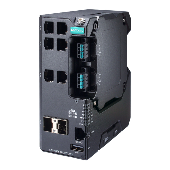
Package Checklist The EDS-4008 Series industrial DIN-rail EtherDevice Switch (EDS) is shipped with the following items. If any of these items are missing or damaged, please contact your customer service representative for assistance. • 1 EDS-4008 Ethernet switch • Quick installation guide (printed) •... - Page 3 1. 100BaseT(X) LED indicator 7. Terminal blocks for power input, 2. 10BaseT(X) LED indicator digital input, and relay output 3. 10/100BaseT(X) ports, 8. LED indicators: STATE (S), ports 3 to 8 FAULT (F), PWR1 (P1), PWR2 4. 100BaseFX port (SC/ST (P2), MSTR/HEAD (M/H), type), port 1 and 2 CPLR/TAIL (C/T), SYNC...
-
Page 4: Mounting Dimensions
5. 1000BaseT(X) LED (P2), MSTR/HEAD (M/H), indicator CPLR/TAIL (C/T), SYNC 6. 10/100BaseT(X) LED 12. Console port (RJ45, RS-232) indicator 13. USB storage port (type A, 7. 100/1000BaseSFP ports, currently disabled) port G1 to G2 14. Model name 15. SmartPoE LED indicator of PoE ports Bottom Panel View 1. - Page 5 EDS-4008-2MST(-T) Models - 5 -...
-
Page 6: Din Rail Mounting
EDS-4008-2GT-2GS(-T)/EDS-4008-4P-2GT-2GS(-T) Models DIN-rail Mounting The DIN-rail mounting kit is fixed to the back panel of the EDS device when you take it out of the box. Mount the EDS device on corrosion- free mounting rails that meet the EN 60715 standard. Installation STEP 1—Insert the upper lip of the DIN rail into the DIN-rail... -
Page 7: Wall Mounting (Optional)
Removal STEP 1—Pull down the latch on the mounting kit with a screwdriver. STEP 2 & 3—Slightly pull the EDS device forward and lift up to remove it from the DIN rail. NOTE Our DIN rail kit now utilizes a quick release mechanism to make it easier for users to remove the DIN rail from the EDS device. -
Page 8: Wiring Requirements
STEP 3—Once the screws are fixed to the wall, insert the four screw heads through the wide parts of the keyhole- shaped apertures, and then slide the EDS device downwards, as indicated in the figure at the right. Tighten the four screws for more stability. - Page 9 NOTE Do not run signal or communications wiring and power wiring through the same wire conduit. To avoid interference, wires with different signal characteristics should be routed separately. • You can use the type of signal transmitted through a wire to determine which wires should be kept separate.
-
Page 10: Wiring The Relay Contact
In order to tighten the wire properly, ① use a small flathead NOTE We suggest the length of the pin type cable terminal is 8 mm. the terminal block connector before and during ② inserting the screwdriver to press the push-in button beside each terminal of wire. -
Page 11: Wiring The Redundant Power Inputs
Wiring the Redundant Power Inputs The EDS device includes both high-voltage and low-voltage products. For the low-voltage (LV models) products, there are two power inputs for redundancy; for the high-voltage (HV models) products, there is only one power input. Refer to the instructions and diagram below on how to connect the wires to the terminal block connector on the receptor. -
Page 12: Communication Connections
STEP 1: Insert the negative (ground)/positive DI wires into the ┴/I terminals, respectively. STEP 2: To keep the DI wires from pulling loose, use a small flat-blade screwdriver to tighten the wire-clamp button on the front of the terminal block connector. STEP 3: Insert the plastic terminal block connector prongs into the terminal block receptor, which is... -
Page 13: Usb Connection
RJ45 Console Port Pinouts Description – USB Connection NOTE The USB function is currently reserved and may be required in the future. It should be noted that this port cannot be used for charging any devices. 10/100BaseT(X) Ethernet Port Connection The 10/100BaseT(X) ports located on the front panel of the switch are used to connect to Ethernet-enabled devices. -
Page 14: 100Basefx Ethernet Port Connection
RJ45 (8-pin) to RJ45 (8-pin) Cross-Over Cable Wiring 100BaseFx Ethernet Port Connection The concept behind the SC/ST port and cable is quite straightforward. Suppose you are connecting devices I and II. As opposed to electrical signals, optical signals do not require a circuit in order to transmit data. Consequently, one of the optical lines is used to transmit data from device I to device II, and the other optical line is used transmit data from device II to device I, for full-duplex transmission. - Page 15 1000BaseT(X) Ethernet Port Connection 1000BaseT(X) data is transmitted on differential TRD+/- signal pairs over copper wires. MDI/MDI-X Port Pinouts Signal TRD(0)+ TRD(0)- TRD(1)+ TRD(2)+ TRD(2)- TRD(1)- TRD(3)+ TRD(3)- 100/1000BaseSFP (mini-GBIC) Fiber Port The Gigabit Ethernet fiber ports on the switch are 100/1000BaseSFP fiber ports, which require using 100M or 1G mini-GBIC fiber transceivers to work properly.
-
Page 16: Reset Button
Reset Button There are two functions available on the Reset Button. One is to reset the Ethernet switch to factory default settings by pressing and holding the Reset button for 5 seconds. Use a pointed object, such as a straightened paper clip or toothpick, to depress the Reset button. This will cause the STATE LED to blink once a second. -
Page 17: Device Led Indicators
NOTE You must enable the Turbo Ring (DIP switch 5) first before using the DIP switch to activate the Master and Coupler functions. NOTE If you do not enable any of the EDS switches to be the Ring Master, the Turbo Ring protocol will automatically choose the EDS switch with the smallest MAC address range to be the Ring Master. - Page 18 Color State Description When the switch is Master/Head/Root of Turbo Ring/Turbo Chain/Fast RSTP. 1. The switch has become the Master of Turbo Ring after Turbo Ring has gone down 2. The switch is set as Head of Turbo Chain and Turbo Chain has gone down MSTR/ Blinking...
- Page 19 Smart PoE LED Indicators Color State Description When the port is connected to IEEE 802.3bt powered device and powered at: • Single signature (PD) Class 5 to 8 • Dual signature (PD) Class 1 Green to 5 1. When the power is not being supplied to a powered device (PD) 2.
-
Page 20: Specifications
Color State Description top LED When the port is inactive or link down. When the port is active and links 10M/ at 10/100Mbps. 100M/ 1000M Blinking When the port’s data is being Amber Copper (4 times/sec) transmitted at 10/100Mbps. bottom When the port is inactive or link down. - Page 21 PoE Output Power 15.4 W for the 802.3af standard, 30 W for the 802.3at standard, 36 W in high power mode, 60 W in 802.3bt standard PoE Output Current 350 mA for the 802.3af standard, 600 mA for the 802.3at standard, 1960 mA for the 802.3bt standard Overload Current Present...
- Page 22 EDS-4008-2GT-2GS-LV(-T) models: 9.41 W EDS-4008-2GT-2GS-HV(-T) models: 11.17 W EDS-4008-4P-2GT-2GS-LVA(-T) models: Without PoE: 11.22 W With PoE: Max. 240 W for total PD power consumption @ 48 VDC input EDS-4008-4P-2GT-2GS-LVB(-T) models: Without PoE: 15.84 W With PoE: Max. 180 W for total PD power consumption @ 48 VDC input;...
- Page 23 EN 61000-4-2 (ESD) Level 4 EN 61000-4-3 (RS) Level 3 EN 61000-4-4 (EFT) Level 4 EN 61000-4-5 (Surge) Level 4 EN 61000-4-6 (CS) Level 3 EN 61000-4-8 Level 4 Shock IEC 60068-2-27 Free Fall IEC 60068-2-32 Vibration IEC 60068-2-6 Rail Traffic EN 50121-4 (Wayside) Traffic Control...
Need help?
Do you have a question about the EtherDevice EDS-4008 Series and is the answer not in the manual?
Questions and answers