Table of Contents
Advertisement
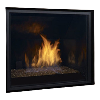
Regency L965E / HZ965E
WARNING:
If the information in these instructions are not followed exactly,
a fi re or explosion may result causing property damage,
personal injury or loss of life.
FOR YOUR SAFETY
Do not store or use gasoline or other fl ammable vapors and
liquids in the vicinity of this or any other appliance.
Installation and service must be performed by a qualifi ed
installer, service agency or the gas supplier.
Tested by:
919-088a
FPI FIREPLACE PRODUCTS INTERNATIONAL LTD. 6988 Venture St., Delta, BC Canada, V4G 1H4
Gas Fireplace
MODELS: L965E-NG L965E-LP HZ965E-NG HZ965E-LP
Installer: Please complete the details on the back cover
and leave this manual with the homeowner.
Homeowner: Please keep these instructions for future reference.
Owners &
Installation Manual
www.regency-fi re.com
FOR YOUR SAFETY
What to do if you smell gas:
Do not try to light any appliance
Do not touch any electrical switch:
do not use any phone in your
building.
Immediately call your gas supplier
from a neighbour's phone. Follow
the gas supplier's instructions.
If you cannot reach your gas
supplier, call the fi re department.
Liberty L965E
Horizon HZ965E
01/17/14
Advertisement
Table of Contents

Related Manuals for Regency L965E-NG


Summary of Contents for Regency L965E-NG
- Page 1 Gas Fireplace Installation Manual Liberty L965E Horizon HZ965E www.regency-fi re.com MODELS: L965E-NG L965E-LP HZ965E-NG HZ965E-LP WARNING: FOR YOUR SAFETY If the information in these instructions are not followed exactly, What to do if you smell gas: a fi re or explosion may result causing property damage, Do not try to light any appliance personal injury or loss of life.
- Page 2 SAFETY FOR SAFE INSTALLATION AND OPERATION OF YOUR “Regency” HEATER, PLEASE CAREFULLY READ THE FOLLOWING INFORMATION: • All Regency gas-fi red appliances must be installed • To prevent injury, if the pilot or pilot and burners in accordance with their instructions. Carefully read all have gone out on their own, open the glass door and the instructions in this manual fi...
-
Page 3: Table Of Contents
Brick panel installation / Removal: Inserts Benefi ts Inserts Benefi ts Log Burner / Ember Bed removal / Installation Log set installation: Full screen door / screen Installation Finishing trim: Liberty L965E Horizon HZ965E Regency L965E / HZ965E Gas Fireplace... - Page 4 After the unit has gone through the fi rst burn, turn the unit off including the pilot, let the unit get cold then remove the glass door and clean it with a good gas fi replace glass cleaner, available at your local Regency dealer. Regency L965E / HZ965E Gas Fireplace...
-
Page 5: Dimensions
When installed, the L965E/HZ965E, must be electrically grounded in accordance with local codes or, in the absence of local codes, with the National Electrical Code, ANSI/NFPA 70, or the Canadian Electrical Code, CSA C22.1. See Page 39. Figure 2. Rating/Lighting Label Location. Regency L965E / HZ965E Gas Fireplace... -
Page 6: Copy Of The Safety Label
ATTENTION: Très chaud quand allumé. Ne touchez pas, les brûlures sévères peuvent résulter. Tenez loin des enfants, des vêtements, des meubles,de l’essence ou d’autres fluides produisant des vapeurs inflammables. DATE OF MANUFACTURE: DATE DE FABRICATION: 2012 2013 2014 2015 Figure 3. Rating Label. Regency L965E / HZ965E Gas Fireplace... -
Page 7: Installation
fi re. If you are unclear about any details contained here, consult with your retailer prior to installation. 24" (610mm) 11" (279mm) 27-3/4" (705mm) **52-5/16" (1329mm) Figure 4. Non-Combustible Material Zone. When Installing a TV above the unit. Regency L965E / HZ965E Gas Fireplace... -
Page 8: Framing
Internal ceiling clearance is 90” Min. Chase Depth when using the heat distribution kit. 44-3/4" (1137mm) Minimum 52-5/16" (1329mm) Minimum 63" 52-5/16" (1600mm) (1329mm) to centerline To Header Figure 6. Typical Framing for Internal Chase - Detailed. Regency L965E / HZ965E Gas Fireplace... -
Page 9: External Chase
Figure 7. Typical Framing for External Chase - General. 24" (610mm) Min. Chase Depth 44-3/4" (1137mm) Minimum 63" (1600mm) 52-5/16" to centerline (1329mm) To Header Figure 8. Typical Framing for External Chase - Detailed. Regency L965E / HZ965E Gas Fireplace... -
Page 10: Corner Framing
INSTALLATION CORNER FRAMING: Figure 9. Typical Framing for Corner - General. 64” (1626mm) 44-3/4" (1137mm) Minimum 2-5/16"(1329mm) Minimum to Header/Shelf Height from Base of Unit Figure 10. Typical Framing for Corner - Detailed. Regency L965E / HZ965E Gas Fireplace... -
Page 11: Framing For Sidewalls And Mantel
Top of Fireplace To Unit Opening Base Figure 11. Mantel Clearances 44-3/4"(1 137mm ) Minimum Framing Width 51-3/4" (1314mm) Minimum Fireplace Base to Combustible Mantel Figure 12. Typical Framing for Sidewalls & Mantel - Detailed. Regency L965E / HZ965E Gas Fireplace... -
Page 12: Typical Framing - Raised Hearth
2-5/16"(1329mm) Minimum to Combustible Header Height from Base of Unit Figure 15. Fireplace Section for a Raised Hearth - WARNING. Figure 14. Typical Framing for a Raised Hearth - Detailed. Regency L965E / HZ965E Gas Fireplace... -
Page 13: Installation Of Fireplace Facing
3) For any fi replace facing without an optional front installed. Figures 17 to 19 highlight the relationships between the fi replace, optional front, and facing installed. Figure 19. Option 3 - Any Fireplace Facing Without Optional Front Installed. Regency L965E / HZ965E Gas Fireplace... -
Page 14: Receiver Installation
The receiver cover also functions as a switch plate and allows for access to the program button, critical for remote control operation. Review the section in this manual regarding the remote control operations for more information on the functions of the receiver. Regency L965E / HZ965E Gas Fireplace... -
Page 15: Allowable Vent Confi Gurations
Only use the restrictors supplied with this appliance. Table 1: Vent Restrictor Sizes. Ø of Flue Restriction Restrictor 3.878” (98.5mm) 3.540” (89.9mm) 3.166” (80.4mm) 2.742” (69.6mm) 2.239” (56.9mm) Figure 23. Allowable Vent Confi gurations Chart. Regency L965E / HZ965E Gas Fireplace... -
Page 16: Vent Termination Restrictions
A vent shall not terminate directly above a side walk or paved driveway that is located between two single family dwellings and it serves both dwellings. Permitted only if verandah, porch, deck, or balcony is fully open on a minimum of two sides beneath the fl oor. NOTE: Venting terminals shall not be recessed into walls or siding. Regency L965E / HZ965E Gas Fireplace... -
Page 17: Approved Vent Parts
EXCEPTION TO WARNING: This product has been evaluated by Intertek for using a Direct Vent GS starting collar in conjunction with Secure Vent, Direct-Temp, and Ameri Vent Direct venting systems. Use of these systems with the Direct Vent GS starting collar is deemed acceptable and does not affect the Intertek WH listing of the appliance. Regency L965E / HZ965E Gas Fireplace... -
Page 18: Installation Of Flue Restrictor
6) Re-install the Light Covers, Firebox Liners, Burners and log sets and the Glass Door. 7) Run the unit for ½ hour to check for proper operations and fl ame appearance. Figure 26: Installation of Flue Restrictor - Close-Up. Regency L965E / HZ965E Gas Fireplace... -
Page 19: Tv Installation Above Unit
Temperature acceptance levels in TV’s vary greatly. Before installing any electronic appliance above this fi replace, fi rst verify temperature requirements from the TV manufacturer. See temperatures above for guidance. Regency will not be responsible for heat damage to electronic appliances. -
Page 20: Planning Your Installation
(4) wood screws, two (2) on either side of the unit’s bottom nailing fl ange. Secure the side stand-offs to the framing members using four (4) wood screws, one (1) for each stand-off and to the header, one (1) wood screw for each facing support. Figure 30: Securing the Unit. Regency L965E / HZ965E Gas Fireplace... -
Page 21: Installation Of Non-Combustible Wall And Hearth Board
fi nal authority. Consult your local building codes before beginning the installation. Figure 32: Typical Minimum Vent Confi gurations Figure 33: Typical Vent Confi gurations - Horizontally Terminated. - Vertically Terminated. Regency L965E / HZ965E Gas Fireplace... -
Page 22: Horizontal Installation
Horizontal Vent Termination bolts onto the fl at portion of the Vinyl Siding Standoff, (Shaded area shown in Figure 37), so that an air space will exist between the wall and the Vent Termination. Regency L965E / HZ965E Gas Fireplace... -
Page 23: Vertical Termination Installation
Assemble the desired lengths of galvanized Pipe and Elbows necessary to reach from the Appliance Adaptor up through the Ceiling Firestop. Ensure that all Pipe and Elbow connections are in their fully twist-locked position. Figure 40: Installation of Ceiling Firestop. Regency L965E / HZ965E Gas Fireplace... - Page 24 Do not fi ll any of the required air spaces with insulation. Figure 43: Installation of Ceiling Fire Stops. Regency L965E / HZ965E Gas Fireplace...
- Page 25 6) screws 7) tube of Mill Pac #946-616 10 Feet 8) plated screws 9) S.S. screws #8 x 1-1/2” drill point 10) vinyl siding standoff Rigid pipe adaptor (Part # 946-601) (standard with unit) Regency L965E / HZ965E Gas Fireplace...
-
Page 26: Heat Distribution Kit Installation
fi replace and secure it in place with fi ve (5) ¼” HWH Hot Air Duct self drilling screws. Figure 3: Install the hot air ducts. Regency L965E / HZ965E Gas Fireplace... - Page 27 Secure the service wires to the strain relief. c) Use the wire nut to join the wires to the service wire. d) Secure the service ground wire to the ground screw on the cover plate. Regency L965E / HZ965E Gas Fireplace...
- Page 28 Fan Bezel Periodic examination of venting systems should be done by a qualifi ed agency. Fan Grille (Not Supplied) 8” X 14” grille is required-purchased separately. Figure 11: Install fan bezel & grille. Regency L965E / HZ965E Gas Fireplace...
- Page 29 Chase Minimum Depth ** Minimum Height from 44 3/4" the base of the unit. (1137mm) Minimum 90" (2286mm) to Internal Ceiling **52 5/16" (1329mm) to Header Figure 12: Installation Clearances with Heat Distribution Kit. Regency L965E / HZ965E Gas Fireplace...
-
Page 30: Power Vent Kit Installation
Selkirk Int. Metal Fab., Excel Direct. Figure 1: Power Vent Kit’s Parts Diagram. 5"x8" to 4"x6 " Vent Reducer 4"x6 " Elbow 5"x8" Elbow Power Vent Figure 2: Below-grade installation with maximum number of elbows. Regency L965E / HZ965E Gas Fireplace... - Page 31 5. Secure the inner thimble to the wall board with screws. 6. Insert the rest of the power vent electrical cord through the bushing on the right bottom of the outer thimble, refer to Figure 7 Regency L965E / HZ965E Gas Fireplace...
- Page 32 10. Align the power vent assembly with the direct vent pipe that is protruding through the thimble. 11. Secure the power vent assembly in place with screws as seen in Figure 8. Figure 8: Install the power vent. Figure 9: Securing cord with the Strain Relief. Regency L965E / HZ965E Gas Fireplace...
- Page 33 16. Remove the protective cover from the PVK Control Box Velcro and secure the power vent control box to the side as shown in Figure 1a. Figure 12: Cover is installed to the power vent assembly. : Removing Access Cover. Figure 13 Regency L965E / HZ965E Gas Fireplace...
- Page 34 Do not cut or remove the grounding prong from this plug. Periodic examination of venting systems should be done by a qualifi ed agency. Figure 16 Changing Valve Wiring. Regency L965E / HZ965E Gas Fireplace...
- Page 35 INSTALLATION SILICONE NOTES: Installer should apply outdoor silicone to the powervent cover on the areas shown below as a preventative measure to help keep water from getting inside. SILICONE THESE AREAS SILICONE THESE AREAS Regency L965E / HZ965E Gas Fireplace...
- Page 36 INSTALLATION Regency L965E / HZ965E Gas Fireplace...
- Page 37 A vent shall not terminate directly above a side walk or paved driveway that is located between two single family dwellings and it serves both dwellings. Permitted only if verandah, porch, deck, or balcony is fully open on a minimum of two sides beneath the fl oor. NOTE: Venting terminals shall not be recessed into walls or siding. Regency L965E / HZ965E Gas Fireplace...
-
Page 38: Door Removal And Installation
4) Lift the Door Frame away, being careful that the glass panel is secure within the Door Frame. Figure 45: Door Latch /Air Adjustment Tool. Figure 46: Door Latch Locations. Figure 47: Door Latch Tool in Place. Figure 48: Door Latch Locations. Figure 49: Top Door Hook. Regency L965E / HZ965E Gas Fireplace... -
Page 39: Gas Hook-Up
This appliance is equipped with a three-prong (grounding) plug for your protection against shock hazard and should be plugged directly into a properly grounded three-prong receptacle. Do not cut or remove the grounding prong from this plug. Figure 51: Location of Electrical Hook-Up. Regency L965E / HZ965E Gas Fireplace... -
Page 40: Lp Gas Conversion
The correct orifi ce sizes for the L965E/HZ965E are LPG - 35 and NG - 62. Figure 53: Removing the Pilot Figure 54: Identifying the Orifi ce. Orifi ce. Figure 55: Removing the Gas Orifi ces. Regency L965E / HZ965E Gas Fireplace... - Page 41 This can be done by using a quality orifi ce gauge and referring to the chart above for the correct offi ce sizing. The rating is listed on the rating plate located under the fi rebox, attached to the unit with a cable. Regency L965E / HZ965E Gas Fireplace...
- Page 42 26. To complete the LP conversion of this appliance, place the “LP Converted” sticker, supplied with the LP conversion kit on the rating plate indicating that this unit has been converted to operate on LP gas. Figure 59: Pressure Test Points. Figure 60: Relationship between ignitor and burner. Regency L965E / HZ965E Gas Fireplace...
-
Page 43: Glass Burner Removal/Installation
2) After the screws are removed, lift out the front panel as shown in Figure 63. Figure 63: Lift Out Front Panel 3) Remove the 4 screws on the burner in locations shown in Figure 64. Figure 64: Burner Screw Locations Regency L965E / HZ965E Gas Fireplace... -
Page 44: Glass Crystal Installation
Figure 72 Figure 73 NOTE: Spa Stones are NOT to be placed anywhere on the Pilot assembly area. Glass Crystals to be installed on the burner and fi rebox fl oor prior to installing stones. Regency L965E / HZ965E Gas Fireplace... -
Page 45: Refl Ective Panel Installation / Removal
Figure 77: Upper Rear Porcelain Panel 4. Repeat same procedure in Step 2 to install Right Side Panel. 5. To remove panels, reverse steps. Figure 75: Side Porcelain Panel and Panel Clip Figure 78: Final Install Regency L965E / HZ965E Gas Fireplace... -
Page 46: Brick Panel Installation / Removal
Slide Panel Clip until it is snug against the Left Side Brick Panel and retighten screw to secure clip. Figure 81: Completed Install 6) To remove Brick Panels, reverse steps. Figure 78: Left Brick Panel Regency L965E / HZ965E Gas Fireplace... -
Page 47: Log Burner / Ember Bed Removal / Installation
Improper positioning of the logs may create carbon build-up and can alter the unit's performance which is not covered under warranty. *Satin black paint is included if touch ups are required. Completed Install Regency L965E / HZ965E Gas Fireplace... - Page 48 6) Identify locator on Log D and opposing Locator on Log B as shown in Figure 91. Place Log D gently on Log B. Figure 88: Log B Position Figure 91: Log D Locator Regency L965E / HZ965E Gas Fireplace...
- Page 49 9) Identify locator on Log G and opposing Locator on the Ceramic Log Burner as shown in Figure 94. Place Log G gently on Burner. Figure 97: Log H Position Figure 94: Log G Locator Figure 95: Log F and G position Regency L965E / HZ965E Gas Fireplace...
-
Page 50: Full Screen Door / Screen Installation
fi nishing material. Figure 97: Location on unit to install Full Screen or Screen. Figure 98: Line up Tabs with slot on Unit Arched Screen Doors Figure 99: Optional Front Installed. Regency L965E / HZ965E Gas Fireplace... -
Page 51: Finishing Trim
Figure 102: Completed Trim install materials Figure 100: Top View - exposed non combustible materials 1. Slide trim into position over exposed non combustible materials. Trim piece Figure 101: Top View - Sliding trim into place Regency L965E / HZ965E Gas Fireplace... -
Page 52: Start-Up & Operation
The Profl ame Remote Control System consists of three (3) elements: 1. Profl ame Transmitter. 2. Profl ame Receiver and a wiring harness to connect the Receiver to the gas valve, stepper motor and Fan Control Module. 3. Profl ame Fan Control Module (FCM) Regency L965E / HZ965E Gas Fireplace... - Page 53 120V outlet. The FCM provides DC power to the Receiver allowing the batteries to be used only when line power is interrupted or lost (see Figure 106). Figure 106: Profl ame Fan Control Module. Regency L965E / HZ965E Gas Fireplace...
-
Page 54: Wall Mounting The Receiver
“ON” and the set temperature is now displayed . To adjust the set temperature, press the Up or Down Arrow Keys until the desired set temperature is displayed on the LCD screen of the Transmitter. Regency L965E / HZ965E Gas Fireplace... -
Page 55: Smart Thermostat (Transmitter Operation)
Function icon is highlighted. Pressing the Up or Down arrow keys will turn the accent lights on or off. A single “beep” will confi rm the reception of the command Figure 110: Remote Control’s Smart Flame Function. Figure 111: Remote Control’s Flame Levels. Regency L965E / HZ965E Gas Fireplace... -
Page 56: Key Lock
CAUTION: Property Damage Hazard. Excessive heat can cause property damage. The appliance can stay lit for many hours. Turn off the appliance if it is not going to be attended for any length of time. Always place the Transmitter where children cannot reach it. Regency L965E / HZ965E Gas Fireplace... -
Page 57: Air Shutter Adjustment
1. The Profl ame DFC Board will try two (2) times for ignition. 2. Each try for ignition will last approximately 60 seconds. 3. The wait time between the two tries is approximately 35 seconds. Regency L965E / HZ965E Gas Fireplace... -
Page 58: Wiring Harness
MAINTENANCE WIRING HARNESS Caution: Label all wires prior to disconnection when servicing controls, Wiring errors can cause improper and dangerous operation. Verify proper operation after servicing. Regency L965E / HZ965E Gas Fireplace... -
Page 59: Air Intake
This process should be completed by a qualifi ed hearth installation technician. Periodic examination of venting systems should be done by a qualifi ed agency. Regency L965E / HZ965E Gas Fireplace... -
Page 60: Light Bulb Replacement
Do not operate with the glass front removed, cracked or broken. Removal and replacement of the glass from the door must be done by a licensed or qualifi ed service person. The glass must be purchased from an authorized Regency dealer, part #50-2002. -
Page 61: Troubleshooting
· See how to reset the board from Lockout command · Reprogram the transmitter to the receiver. No communication between the remote control and the receiver · Follow the initializing system for the fi rst time Regency L965E / HZ965E Gas Fireplace... - Page 62 · Check for proper venting and blockage of the vent termination · See also “Burners will not remain lit” Incorrect rating input · Check manifold pressure and clock input rating for over-fi ring Regency L965E / HZ965E Gas Fireplace...
-
Page 63: Appendix A - Optional Reduced Ceiling Height Installation
The main difference is the install depth is changed to 26½” (673mm) to compensate for the reduced vertical clearances. The width and framing dimensions remain unchanged to the regular installations shown earlier in this manual. 44-3/4" (1137mm) **52-5/16" (1329mm) Regency L965E / HZ965E Gas Fireplace... -
Page 64: Parts List
PARTS LIST Regency L965E / HZ965E Gas Fireplace... - Page 65 Wire Harness - IPI 911-006 Pilot Assembly - NG 911-007 Pilot Assembly - LP 706-026 Vent Restrictor Set 706-921 Regency Heat Distribution Kit 706-922 Power Vent Kit 706-929 Mesh Guard 706-940 Full Screen Doors Regency L965E / HZ965E Gas Fireplace...
-
Page 66: Warranty
Regency Fireplace Products is the manufacturer of the Regency line of heating products. At Regency, our commitment to the highest level of quality and customer service is the most important thing we do. Each Regency stove is built on a tradition of using only the fi nest materials and is backed by our Exclusive Lifetime Limited Warranty to the original purchaser. - Page 67 Labour rates are set per component and as such total labour costs may not be covered. 27. Regency Fireplace Products is not liable for freight or labour on any stove replaced in-fi eld and is not liable for travel costs for service work.
- Page 68 ® Register your Regency warranty online www.regency-fi re.com Reasons to register your product online today! • View and modify a list of all your registered products. • Request automatic email notifi cation of new product updates. • Stay informed about the current promotions, events, and special offers on related products.
Need help?
Do you have a question about the L965E-NG and is the answer not in the manual?
Questions and answers