Table of Contents
Advertisement
Quick Links
Advertisement
Table of Contents

Related Manuals for Uniden UBC125XLT


Summary of Contents for Uniden UBC125XLT
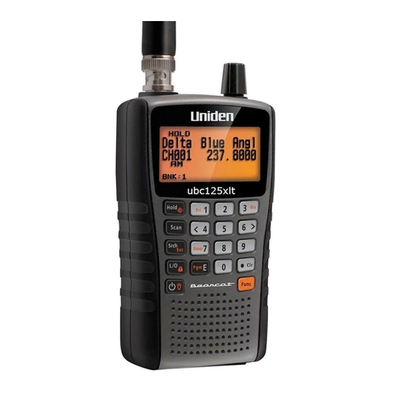
- Page 1 UBC125XLT Scanner...
-
Page 2: Precautions
Changes or modifi cations to this product not expressly approved by Uniden, or operation of this product in any way other than as detailed by this Operating Guide, could void your authority to operate this product. -
Page 3: Table Of Contents
CONTENTS PRECAUTIONS ........... . . 2 INTRODUCTION . - Page 4 SETTING UP YOUR SCANNER ........29 SCROLL CONTROL Using the Knob .
- Page 5 CLOSE CALL ............55 Using the Close Call Feature .
-
Page 6: Introduction
INTRODUCTION Thank you for purchasing a Uniden UBC125XLT Handheld Scanner. The scanner is versatile, compact, and easy to use. In addition to its standard scanning features, your scanner also includes Close Call™ RF capture technology designed to help you detect and identify strong local radio signals in your area. - Page 7 Close Call Do-Not-Disturb - checks for Close Call activity in between channel reception so active channels are not interrupted. Close Call Temporary Store - temporarily stores and scans the last 10 Close Call hits in the Close Call Hits bank. PC Programming - you can download information into the scanner and upload to the scanner via your personal computer.
- Page 8 Priority Scan with Do Not Disturb - lets you program one channel in each bank (10 in all) and then have the scanner check each channel every 2 seconds while it scans the banks so you don’t miss transmissions on those channels. Do-Not Disturb keeps the scanner from interrupting transmissions during receiving.
- Page 9 Modulation - Lets you select a modulation (AM or FM) each band coverage band. Display Backlight - You can turn on/off the LCD backlight, set it operate on squelch only, keypress only, or both. Signal Strength Meter - shows the signal strength for more powerful transmissions.
-
Page 10: Frequency Range
Battery Low Alert - the icon will blink in the display and a tone warns you every 15 seconds when the battery power gets low. FREQUENCY RANGE This table lists the frequency ranges, default step frequency, default modulation, and type of transmissions you can hear for each range. -
Page 11: Band Plan 2
FREQUENCY (MHz) STEP (kHz) MODE LOWER UPPER 160.6000 162.0250 6.25 162.0312 162.5937 6.25 162.6000 174.0000 6.25 225.0000 399.9875 12.5 400.0000 439.9937 6.25 440.0000 449.9937 6.25 450.0000 465.9937 6.25 466.0000 469.9937 6.25 470.0000 512.0000 6.25 806.0000 960.0000 12.5 BAND PLAN 2 FREQUENCY (MHz) STEP (kHz) MODE... -
Page 12: Included With Your Scanner
6.25 450.0000 465.9900 10.0 466.0000 469.9900 10.0 470.0000 512.0000 6.25 806.0000 960.0000 12.5 INCLUDED WITH YOUR SCANNER • UBC125XLT scanner with attached belt clip • Antenna • Rechargeable 2300mAh Ni-MH Batteries • USB cable • AC-USB adapter • Wrist strap... -
Page 13: Scanning Basics
WHAT IS SEARCHING? The UBC125XLT can search for active frequencies. This is diff erent from scanning because you are searching for frequencies that have not been programmed into the scanner. -
Page 14: Understanding Scanning
UNDERSTANDING SCANNING What is CTCSS/DCS? Your scanner can monitor systems using a Continuous Tone Coded Squelch System (CTCSS) and Digital Coded Squelch (DCS) system, which allows the squelch to open only when the tone you have programmed with a specifi c frequency is received along with a transmission. -
Page 15: Conventional Scanning
with a signal, the scanner’s squelch remains closed and you hear nothing. Refer to the Reference section of this manual for tables showing the available CTCSS frequencies and DCS codes. Conventional Scanning Conventional scanning is a relatively simple concept. Each group of users in a conventional system is assigned a single frequency (for simplex systems) or two frequencies (for repeater systems). -
Page 16: Repeater Operation
construction job sites, and with inexpensive consumer radios such as PMR radios. The range is typically 1-8 miles, depending upon the terrain and many other factors. Repeater Operation Repeater systems use two frequencies: one transmits from the radio to a central repeater; the other transmits from the repeater to other radios in the system. -
Page 17: Custom Search Banks
searches that can be used just like the channel storage banks to search these frequencies in Service Search mode. Custom Search Banks Custom Search Banks let you program and search 10 custom search ranges. During custom search, the scanner starts searching with the lowest frequency in the search range you select to the highest frequency in the range. -
Page 18: Connecting The Antenna
CONNECTING THE ANTENNA Align the slots around the antenna's connector with the tabs on the scanner's BNC connector. Slide the antenna's connector down over the scanner's connector. Rotate the antenna connector's outer ring clockwise until it locks into place. Connecting an Optional Antenna The scanner's BNC connector makes it easy to connect a variety of optional antennas, including an external mobile antenna or outdoor base station antenna. -
Page 19: Adjusting The Belt Clip
You can power the scanner using alkaline (ALK) non- rechargeable batteries (not supplied) or the included Nickel Metal-Hydride (Ni-MH) rechargeable batteries. [Uniden provides a USB cable to charge the Ni-MH batteries on initial installation and to recharge them through your computer or through a power adapter that provides USB charge power.]... -
Page 20: Installing Non-Rechargeable Batteries
• Always remove old or weak batteries. Batteries can leak chemicals that destroy electronic circuits. • Do not mix old and new batteries, diff erent types of batteries (standard, alkaline, or rechargeable), or rechargeable batteries of diff erent capacities. • Do not use and charge Ni-Cd batteries; this may cause a safety hazard and damage the scanner. -
Page 21: Charging The Ni-Mh Batteries
NOTE: If you connect to a computer's USB port, the PC will prompt you for the drivers for your scanner. USB drivers and optional programming software are available for download from http://www.butel.nl/ubc125xlt . These will also be available on the CD’s with ARC125 Software. - Page 22 The scanner displays Charging while it charges the batteries and Charge Complete when the Ni-MH batteries are completely charged. Diff erent status messages may display depending on the battery type and scanner status: LCD Message Batt. Meaning Scanner Type Cond. Charging Ni-MH Scanner is charging.
-
Page 23: About Your Scanner
ABOUT YOUR SCANNER We use a few simple terms in this manual to explain the features of the scanner. Familiarize yourself with these terms and the scanner's features, and you can put the scanner to work for you right away. Simply determine the type of communications you want to receive, then set the scanner to search those communications. -
Page 24: Getting To Know The Scanner
GETTING TO KNOW THE SCANNER If your scanner's keys seem confusing at fi rst, the following information should help you understand each key's function. Your scanner's keys have various functions labeled on the key tops and below the keys. The keys operate in Normal mode and Function mode. - Page 25 Key/ Press to... Press Func and Icon this key to... 4/< • Enter 4. • Scroll left in Edit Tag mode. 6/> • Enter 6. • Scroll right in Edit Tag mode. Toggle the Key- 7/Beep Enter 7. beep setting. 9/Mod Enter 9.
- Page 26 Key/ Press to... Press Func and Icon this key to... L/O/ • Temporarily lock out a channel Lock or unlock the keypad. or search frequency (press once). • Permenantly lock out a channel or search frequency (press twice). • Unlock a locked out channel or search frequency.
-
Page 27: Turning On The Scanner
TURNING ON THE SCANNER Note: Make sure the scanner's antenna is connected before you turn it on. You can select the band plan (Band Plan 1 or 2) when you turn on the scanner. When you press and hold for 1 second to turn on the scanner, also press and hold 1 for Band Plan 1 or 2 for Band Plan 2. - Page 28 Item Meaning • Channel Name in Scan/Scan Hold mode. • Custom/Service Search Bank Name. • Quick Search in Quick Search mode. • Close Call Hits in Scan/Scan Hold mode. • Close Call in Close Call Only mode. • Scan in Scan mode. •...
-
Page 29: Setting Up Your Scanner
Using the SCROLL CONTROL Knob Turn the SCROLL CONTROL knob on top of the UBC125XLT to: • Select channels • Adjust volume • Adjust squelch •... -
Page 30: Adjusting The Volume
Adjusting the Volume Press SCROLL CONTROL; The volume level indicator and battery voltage display. Turn SCROLL CONTROL to adjust the volume level from 0 to 15. Press SCROLL CONTROL to set the volume. To exit Volume Level mode, press SCROLL CONTROL again or wait 10 seconds to return to the previous mode. -
Page 31: Adjusting The Contrast
Scroll to select one of the following settings: • Always Off - Backlight is always off . • Always On – Backlight is always on. • On with Squelch - Backlight is on while squelch is open and until delay expires. •... -
Page 32: Setting The Charging Timer
; the Display/ To adjust the contrast, press Func then Charge menu displays Scroll to Set Contrast and press Pgm/E. Scroll to see the contrast settings. When you have selected a setting, press Pgm/E to set it and return to the previous menu. Press . -
Page 33: Using The Keypad Lock
2000mAh 12 hours 2100mAh 13 hours 2200mAh 13 hours 2300mAh 14 hours Note: The batteries will take longer to charge when the scanner is in use. Press . Clr to exit. Using the Keypad Lock Use the scanner's keypad lock to protect it from accidental program changes. -
Page 34: Pc Programming
When you connect your scanner to your PC, a series of screens will appear to assist you. USB drivers and optional programming software are available for download from http://www.butel.nl/ubc125xlt . These will also be available on the CD’s with ARC125 Software. PROGRAMMING CHANNELS Now that you have confi gured your scanner, you are ready to start using your scanner’s preprogrammed service banks,... - Page 35 Note 2: You can quickly store frequencies in Scan Hold mode by entering the frequency and pressing Pgm/E. Scroll to highlight Enter Frequency and press Pgm/E. You will see the channel number and currently programmed frequency. (To return to the previous screen, press . Clr.) Use number keys and .
-
Page 36: Programming Channel Text Tags
PROGRAMMING CHANNEL TEXT TAGS You can customize your channels by programming text tags (up to 16 characters in length) for easier channel frequency identifi cation. The default tag is the bank number followed by the channel number in the bank. To select a channel, press Hold and then enter the channel number. -
Page 37: Setting Channel Modulation
Scroll to select Set CTCSS/DCS and press Pgm/E. Scroll to select one of the following options: • Off - the scanner ignores all tones and opens squelch on any signal • CTCSS - the scanner prompts the user for the appropriate tone. -
Page 38: Setting The Priority Channel
Scroll to select Set Modulation and press Pgm/E. Scroll to select modulation from the following options : • AM - the scanner uses AM modulation. • FM - the scanner uses FM modulation. Press Pgm/E to save and return to the Channel menu. Note: If current frequency is air band, you can not select FM modulation. -
Page 39: Setting Channel Delay
SETTING CHANNEL DELAY This setting controls how many seconds the scanner waits after a transmission ends before resuming scanning. If you select a minus delay time, the scanner stops on the transmission for the setting time, then automatically resumes scanning. (Default = 2 seconds) To select a channel, press Hold then enter the channel number. -
Page 40: Deleting Channels
DELETING CHANNELS You can delete all programming for a channel. Press Hold then enter the channel number to delete. Press Pgm/E to enter the Channel menu. (You can also press Hold and scroll to the channel; press Func then Pgm/E.) Scroll to select Delete Channel and press Pgm/E. -
Page 41: Scanning Stored Channels
SCANNING STORED CHANNELS Press Scan to begin scanning channels. The scanner scans through all unlocked channels in the enabled banks in channel order. When the scanner fi nds a transmission, it stops on it. When the scanning of all normal banks ends, the scanner scans a channel storage bank that is named Close Call Hits (if enabled). -
Page 42: Priority Scan Modes
• To hold on a channel, press Hold. • To step through the channels, turn the SCROLL CONTROL in Hold mode. Press Hold to resume. While monitoring a transmission, the upper line displays the current bank and bank channel number (or name if tagged) and the lower line displays the channel number in the scanner and frequency with the direction indicator (↑or ↓). -
Page 43: Manually Selecting A Channel
• Priority Off - does not check for priority channels. • Priority DND - checks Priority channels every 2 seconds only when not receiving. If you set Priority mode to Priority DND, the scanner turns on the icon during scanning or searching. -
Page 44: Unlocking Channels
and TL/O briefl y appear in the display. Turning the scanner off clears the temporary lockout. Press L/O twice quickly to permanently lock out the channel. Locked Out and L/O briefl y appear in the display. Turning the scanner off will NOT clear the lockout. If you lock out a channel in Scan mode, the scanner will resume scanning from the next channel. -
Page 45: Service Search Mode
Press and hold L/O until Confi rm Unlock All Channels? appears in the display. Press Pgm/E to unlock all or . Clr to cancel. SERVICE SEARCH MODE If you do not have a reference to frequencies in your area, use a search to fi nd a transmission. -
Page 46: Service Search Receive/Hold Modes
Service Search Receive/Hold Modes To hold on a frequency, press Hold. To step through the frequencies, turn SCROLL CONTROL while in Hold mode. Press Hold to resume. While monitoring a transmission, the upper line displays the current service bank name and the lower line displays the channel number (if defi ned) and current frequency with the direction indicator (↑or ↓). - Page 47 This feature lets you search through the preset frequency ranges. (See also Programming Custom Search Ranges, page 51). The preset frequency ranges are: Bank No. Frequency (MHz) 25.0000 - 27.9999 28.0000 - 30.1999 30.2000 - 49.9999 50.0000 - 88.0000 108.0000 - 136.9999 137.0000 - 143.9999 144.0000 - 174.0000 225.0000 - 399.9999...
-
Page 48: Custom Search Receive/Hold Modes
• If you want to change the search direction or if it is a long transmission and you want to continue searching, turn SCROLL CONTROL or press Srch/Svc. Custom Search Receive/Hold Modes To hold on a frequency, press Hold. To step through the frequencies, turn SCROLL CONTROL in Hold mode. -
Page 49: Quick Search Receive/Hold Modes
To start a Quick Search in Scan or Search mode, press Hold to hold on any channel or frequency. Enter the new frequency (include a decimal point so you don’t go to a channel) and press Hold again to set the frequency. At Quick Search, press Hold to start searching. -
Page 50: Search Options
The modulation, Priority mode icon (if Priority is enabled), any CTCSS/DCS received (if enabled), and the Close Call icon (if CC Pri or CC-DND is enabled) will also appear in the display. • To store a frequency, press Pgm/E. See Storing Found Search Frequencies, page 52. -
Page 51: Programming Custom Search Ranges
• 1 sec - waits 1 second for a reply then resumes. • 2 sec - waits 2 seconds for a reply then resumes. • 3 sec - waits 3 seconds for a reply then resumes. • 4 sec - waits 4 seconds for a reply then resumes. •... -
Page 52: Storing Found Search Frequencies
Turn SCROLL CONTROL to Search Bank 1-10 and press Pgm/E. You will see the previously programmed lower frequency. At Lower, press Pgm/E and use the keypad to enter the lower limit frequency then press Pgm/E. Scroll to Upper and press Pgm/E. You will see the previously programmed upper frequency. -
Page 53: Locking Out Search Frequencies
Locking Out Search Frequencies You can lock up to 200 search frequencies: 100 temporary frequencies and 100 permanent frequencies. While receiving a frequency in any Search or Search Hold mode, press L/O once to temporarily lock out the frequency. Temporary L/O and TL/O briefl y appears in the display. When the scanner is turned off , the temporary lockout is cleared. -
Page 54: Unlocking All Search Frequencies
Unlocking all Search Frequencies Press Func then Pgm/E in any Search or Search Hold mode to view the Search menu. Scroll to Review Lockouts and press Pgm/E. Scroll to Unlock All and press Pgm/E. Then Confi rm Unlock All Frequencies? appears. Press Pgm/E to confi rm or .Clr to cancel. -
Page 55: Setting Modulation
Setting Modulation You can change the modulations of each band. Selected modulation aff ects both search and Close Call. For CB band and HAM band, selected modulation also aff ects CB band and HAM band service search. For Air band, the modulation is AM only. Press Func then 9/Mod to change the modulation while holding the frequency. -
Page 56: Selecting Close Call Modes
can also set the frequency bands where you want the scanner to look for transmissions. The scanner also automatically stores the last 10 hits received into a temporary bank called "Close Call Hits" in any Close Call mode. The hits go away when you cycle power. You can also store these temporary frequencies into channel storage banks. -
Page 57: Close Call Only Mode
• Close Call DND - only checks for Close Call hits between transmissions avoiding breaks in current transmiss • Close Call Pri (Priority) - checks for Close Call hits every 2 seconds, even during transmissions. • Close Call Only - performs continuous Close Call checks until you exit by pressing Scan or Srch/Svc. - Page 58 • Press any key (other than Hold) to view the displayed frequency. While monitoring a Close Call transmission, the scanner displays Close Call on fi rst line and the monitoring frequency on the second line. The modulation and any CTCSS/DCS received (if enabled) will also appear on the display.
-
Page 59: Set Close Call Bands
Set Close Call Bands This setting allows you to select the bands searched for all Close Call modes. Press Func then Hold to view the Close Call menu. Scroll to Close Call Bands and press Pgm/E. Scroll to each band you want to enable/disable and press Pgm/E. -
Page 60: Close Call Hits Bank
• Alert Light - Controls whether the scanner fl ashes the display backlight when Close Call detects a signal. • Back - returns to previous menu. Scroll to any option you want to enable/disable and press Pgm/E. Scroll to On or Off and press Pgm/E Press .Clr (or scroll to Back and press Pgm/E) to return to the Close Call menu. -
Page 61: Close Call Ctcss/Dcs Search
on the transmission for the preset time and then automatically resumes scanning. (Default = 2 seconds). This setting aff ects both Search and Close Call. Press Func then Hold to view the Close Call menu. Scroll to Set Delay and press Pgm/E. Scroll to select the delay time from following options: •... -
Page 62: Technical Specifications
TECHNICAL SPECIFICATIONS Size: 67mm(W) x 32.7mm(D) x 115mm(H) Weight: 175g (without antenna and battery) Operating Temperature: – 20º C to + 60ºC Close Call – 10º C to + 50ºC Power Requirements: 2 AA Rechargeable Ni-MH Batteries (2.4V DC) 2 AA Alkaline Batteries (3.0V DC) Connect to AC adapter or PC with USB cable (5.0V DC 500mA) LCD Display: 64 X 128 Full Dot Matrix LCD with orange-color... - Page 63 Custom Searches: 10 Bands Search Band: 25 searchable bands Scan Rate: 80 channels/second Search Rate: 90 steps/second 270 steps/second (5kHz step) Scan Delay: 2 seconds (default) Audio Output Power: Internal Speaker - 360mW nominal (24ohm) Headphone (L-ch) 4mW nominal (32ohm) Antenna: 50 ohms (Impedance) Sensitivity (12dB SINAD) Nominal...
- Page 64 (FM) 173.225 MHz 0.2 uV VHF High 2 Band (AM) 225.050 MHz 0.4 uV (AM) 272.950 MHz 0.4 uV (AM) 315.050 MHz 0.4 uV UHF Band (AM) 325.050 MHz 0.4 uV (FM) 406.875 MHz 0.3 uV (FM) 511.9125 MHz 0.3 uV Public Service Band (FM) 806.000 MHz...
- Page 65 (FM) 406.875 MHz 180 uV (FM) 857.150 MHz 280uV Signal Noise Ratio (nominal) VHF Low Band (AM) 25.0050 MHz 46dB (FM) 54.050 MHz 42dB Aircraft Band (AM) 127.175 MHz 47dB VHF High 1 Band (FM) 161.9875 MHz 42dB VHF High 2 Band (AM) 272.950 MHz 46dB...
-
Page 66: References
REFERENCES CTCSS FREQUENCIES 67.0 69.3 71.9 74.4 77.0 79.7 82.5 85.4 88.5 91.5 94.8 97.4 100.0 103.5 107.2 110.9 114.8 118.8 123.0 127.3 131.8 136.5 141.3 146.2 151.4 156.7 159.8 162.2 165.5 167.9 171.3 173.8 177.3 179.9 183.5 186.2 189.9 192.8 196.6 199.5... -
Page 67: Dcs Codes
DCS CODES BIRDIES All radios can receive "birdies" (undesired signals). If your scanner stops during Scan mode and no sound is heard, it might be receiving a birdie. Birdies are internally generated signals inherent in the electronics of the receiver. Birdies are especially present at the 16MHz multiple (ex. -
Page 68: Declaration Of Conformity
Chuo-Ku, Tokyo 104-8512 Japan declare, under our sole responsibility, that this equipment: Uniden Bearcat model UBC125XLT is in compliance with the essential requirements and other relevant provisions of the Council Directive1999/5/EC. The product is in conformity with the following European... - Page 72 THANK YOU FOR BUYING A UNIDEN PRODUCT. © 2013 Uniden Corporation. Printed in Vietnam. U01UB374ZZZ(0)
Need help?
Do you have a question about the UBC125XLT and is the answer not in the manual?
Questions and answers
WHERE IS SCROLL BUTTON ?/