
Related Manuals for Uniden UM385


Summary of Contents for Uniden UM385
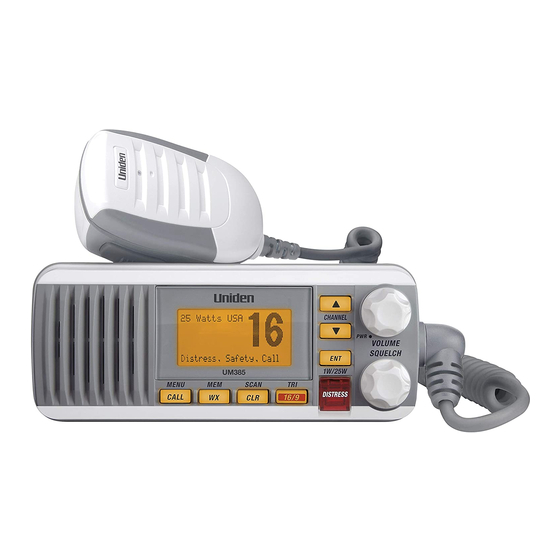
- Page 1 UM385 WATERPROOF DSC MARINE RADIO RADIO MARITIME ASN HYDROFUGE OWNER’S MANUAL GUIDE D’UTILISATION...
-
Page 2: Making A Voice Distress Call
Lift the red cover. Press and hold the button for three seconds. Your radio MAKING A DISTRESS CALL transmits your boat’s location every few minutes until you receive a response. DISTRESS Lift the red cover and press the button. DISTRESS the radio displays Enter User MMSI, cancel the automatic distress call and make a NOTE: IF normal voice distress call. -
Page 3: Faire Un Appel De Détresse Vocal
Soulevez le couvercle rouge. Maintenez la touche DISTRESS enfoncée FAIRE UN APPEL DE DÉTRESSE pendant trois secondes. Votre radio transmet l’emplacement de votre bateau toutes les quelques minutes jusqu’à ce qu’il reçoive une réponse. Soulvez le couvercle # REMARQUE : Si la radio affiche Enter User MMSI (Entrer l’ISMM de rouge et appuyez sur le l’utilisateur), annulez l’appel de détresse automatique et faites un bouton... -
Page 4: Cómo Hacer Una Llamada De Socorro Por Voz
14. Suelte el botón PUSH TO TALK y escuche. Si no recibe una contestacion dentro de 30 segundos, repita su llamada, comenzando con el paso 3, descrito arriba. Visite www.uniden.com para bajar el manual en español de la radio UM385. -
Page 5: Table Of Contents
CONTENTS MAKING A VOICE DISTRESS CALL ................II FAIRE UN APPEL DE DÉTRESSE VOCAL ..............III CÓMO HACER UNA LLAMADA DE SOCORRO POR VOZ ........IV INTRODUCTION ................. 1 FEATURES ......................1 EXPLANATION OF TERMS ..................1 GETTING STARTED ....................2 What’s Included ....................2 Parts of the Radio ..................... - Page 6 SPECIFICATIONS ................35 RADIO SPECIFICATIONS ..................35 REFERENCE TABLES ..................... 36 Channel Descriptions and What They Mean ............36 MARINE RADIO CHANNEL CHART ................ 37 WEATHER CHANNELS AND FREQUENCIES (US, CAN, AND INT) ......41 EMERGENCY ALERT SYSTEM (SAME) INFORMATION ......... 41 Types of Events....................
-
Page 7: Introduction
INTRODUCTION • Waterproof Radio – Complies with IPX4 waterproof standards, which means the FEATURES radio is resistant to damage from rain or splashing water. • Large, dot matrix display • Advanced DSC Class D functions, including Test Calling • Channel select buttons on the microphone •... -
Page 8: Getting Started
GETTING STARTED What’s Included VHF Marine Radio Microphone Mounting Hanger and Mounting Bracket and Knobs Mounting Hardware Mounting Hardware DC Power Cable Accessory Cable Parts of the Radio VOLUME-PWR (power) CHANNEL UP / knob (turn clockwise to CHANNEL DOWN ENT- 1W/25W increase volume) display buttons... -
Page 9: Parts Of The Microphone
Button Press to... Press and hold to... Go to previous menu or cursor Start scanning the channels saved CLR-SCAN position in menu mode. in memory. Listen to the current weather Save a channel into memory or WX-MEM conditions in your area. remove a channel from memory. -
Page 10: Turning On The Radio
Turn the VOLUME-PWR knob clockwise to turn on the radio. As it powers on, the radio TURNING ON THE RADIO displays the user MMSI number; if there is no MMSI set, the radio displays When it powers on, the radio selects the last channel used. MMSI not entered. -
Page 11: Normal Mode Operation
Watch What It Does Use It When To Turn it on./off... Mode Checks for alerts You want to be made Select WX-ALERT Mode in on the last weather Weather aware of severe weather channel you Setup submenu, and then Alert conditions in your area. -
Page 12: Using The Radio In Normal Mode
x To transmit, press and hold PUSH TO TALK on the microphone. Release the button when Using the radio in normal mode you are finished talking. x For the best sound quality, hold the microphone about two inches from your mouth while you’re talking. -
Page 13: Scan Mode
You can activate Weather Alert Watch and Triple/ Dual Watch at the same time. The radio Normal mode with both Weather Alert and Triple/Dual Watch performs both checks at their scheduled time. Monitoring Channel 25 09 16 09 16 09 16 Triple Watch: Every 2 seconds, the radio checks channels 9 &... -
Page 14: Weather Mode
x To end the scan, press the microphone’s PUSH TO TALK, CALL-MEM, or WX-MEM buttons. The radio remains on the last scanned channel. If you activate Weather Alert Watch while operating in scan mode, the radio checks the Scan mode with Weather Alert Watch most recently-used weather channel every seven seconds, then continues scanning the next channel in memory. -
Page 15: Using Your Radio
Weather Current Weather Band mode is on channel Alert number Flashing: An alert has been issued Steady: Weather Type of alert (If the text is too Alert Watch is on Hurricane Warning long, it scrolls.) x You cannot transmit while in weather mode. Using the radio in weather mode x To enter weather mode, press WX-MEM. -
Page 16: Using Your Radio
Press and hold - CALL Setup USA/CAN/INT Dual/TriWatch GPS Setup 1W/25W FIPS Codes Auto CH SW POS Reply Test Reply Channel Name Group MMSI User MMSI WX Alert Mode [Exit] System Contrast Lamp Adjust Key Beep 1W/25W [Exit] [Exit] (Close Menu) x An arrow on the left side indicates the current selection. - Page 17 including any noise on the channel. Setting the squelch level higher filters out channel noise and lets only actual radio transmissions through. Strong signals Weak signals Noise While listening to a channel, adjust the SQUELCH knob until the noise is filtered out and Medium High Squelch...
- Page 18 # NOTE: Don’t forget to change the transmission setting back to 1 Watt when you move closer to other stations. # NOTE: By default, when you change to channel 16, the radio automatically boosts the power to 25 Watts. Be sure to change the power back to 1 Watt if you are not making an Some channels (for example, channels 13 and 67) limit the power of transmission to 1 emergency transmission.
-
Page 19: Changing Display And Sound Options
x For information on the Canadian implementation of FIPS codes, called Canadian Location Codes, see the website of the Meteorological Service of Canada (MSC): http:// www.msc.ec.gc.ca/msb/weatheradio/transmitter/index_e.cfm # NOTE: If you travel outside the areas you have entered into your radio, you may not hear alerts that affect your new location. -
Page 20: Using Digital Selective Calling (Dsc) Features
Key beep is the tone that sounds when you press a key or a button. To turn off the key Turning the key beep on and off beep, press and hold CALL-MENU while the radio is idle. Select System and then Key Beep. Choose OFF to turn off the key beep. -
Page 21: What Is An Mmsi Number
DSC provides a system for automated distress calls. At the touch of a button, the radio can transmit your MMSI number, the nature of your distress, and your current position based on data from your GPS receiver. The radio repeats the distress call every few minutes until it receives an acknowledgement. - Page 22 The radio only allows you to enter the user MMSI once. If you need to re-enter the User Follow the steps below to enter your individual or user MMSI number into the radio: MMSI number, Visit our webiste for assistance at www.uniden.com. CALL...
-
Page 23: Using The Directory
next digit. Enter the remaining seven digits of the MMSI number in the same way. If you make a mistake while entering a number, press CLR-SCAN to erase the wrong number and the cursor is moved to the left digit. 5. - Page 24 8. When the first character is correct, press ENT-1W/25W button. The cursor moves to the next character. Enter the remaining 11 characters of the name. If the name is shorter than 12 characters, press and hold ENT-1W/25W to complete the name entry.
-
Page 25: Calling A Single Station (Individual Call)
To call a single station with DSC, follow the steps below: Calling a single station (Individual Call) 1. Press CALL-MENU to display the call menu. 2. Select Individual. 3. The radio displays the names listed in your directory; use CHANNEL UP and CHANNEL DOWN to choose the directory entry you want to call and press ENT- 1W/25W. - Page 26 Group calling calls all the stations that share your group MMSI. You must have a group Calling a particular group of stations (Group Call) MMSI programmed into the radio to make a group call, and the stations (boats) you are calling must have this same group MMSI programmed into their radios.
-
Page 27: Receiving A Dsc Call
Collision Piracy. Armed Grounding Overboard Capsizing 3. If no MMSI number has been programmed, the radio prompts you to enter your MMSI number. While the radio is waiting for a response, it gives you the option of canceling the call. To Canceling an automatic distress call cancel the distress call, choose Cancel and press ENT-1W/25W. -
Page 28: Test Calls
5. Select the call you want to see the details of. Use CHANNEL UP and CHANNEL DOWN to see all of the information. The log displays different information depending on type of call received. See the table below for the information stored for each type of call: DSC Call Type Receive Log Information Distress... - Page 29 2. Select Test. 3. The radio displays the names listed in your directory; use CHANNEL UP and CHANNEL DOWN to choose the directory entry you want to send a test call to and press ENT-1W/25W button. If you want to send a test call to a station that is not in your directory, select Manual.
- Page 30 If you want the radio to automatically reply to all test call, you can enable automatic test Enabling automatic test call reply call reply. 1. Press and hold CALL-MENU to display the normal menu. 2. Select Setup and then Test Reply. Choose Auto and press ENT-1W/25W. The radio will automatically send an acknowledgement when it receives a test call.
- Page 31 When another station requests your current position, the radio displays the following screen: Receiving a position request (Position Reply) To send your current position to the other station, select Reply; the radio transmits your latitude and longitude to the other station. If you select Reply but the radio does not have valid GPS data, it transmits the reply code with No Position.
-
Page 32: Putting The Radio Into Standby
If you are leaving your radio or do not wish to answer any DSC calls, you can put your radio Putting the Radio into Standby in standby mode. If your radio receives an individual call, it will automatically respond with a message that indicates your radio is currently unattended. Follow the steps below to put your radio in standby: CALL 1W/25W... - Page 33 CHANNEL UP and CHANNEL DOWN to change the first character. 5. When the first character is correct, press ENT-1W/25W. The cursor moves to the next character. Enter the remaining 11 characters of the name. If the name is shorter than 12 characters, press and hold ENT-1W/25W to complete the name entry.
-
Page 34: Installing The Hardware
INSTALLING THE HARDWARE Your radio can sit at any angle in the mounting bracket so it can easily accommodate MOUNTING THE RADIO the best location. First, determine the best place to mount the radio. For optimum performance, find a location that can: x Properly support the weight of the radio, approximately 2.2 pounds or 1.1 kilograms. -
Page 35: Connecting The Radio
Hex nut Spring washer Washer Mounting surface Mounting bracket Hex bolt Install the radio back into the mounting bracket. To operate correctly, your radio requires two electrical connections: CONNECTING THE RADIO x providing it with power from the boat’s electrical system x connecting a VHF-FM marine antenna to the antenna connector Power Supply Requirements VHF Antenna Requirements... -
Page 36: Connecting The Accessory Cable
Use the accessory cable to connect the radio to a GPS receiver, a GPS chartplotter, and an Connecting the Accessory Cable external speaker. The wiring diagram below shows the connections for each accessory. Accessory cable wires Connects to... Brown: NMEA_OUT (-) Chartplotter NMEA Data Input (-) Green: NMEA_IN (-) GPS receiver NMEA Data Output (-) or GND... - Page 37 Time 06/20 11:00:00 Date Current Course 30. 0 KT channel 40. 610 N Latitude 46. 564 E Longitude Speed If the GPS does not send coordinates within 30 minutes, an audible alert sounds once and GPS Data: External Status the display shows Input GPS. This message remains until the coordinates are updated. After 4 hours, the audible alert sounds again if no coordinates are received and the GPS is connected.
-
Page 38: Connecting To A Chartplotter
Your radio provides a standard NMEA0183 GPS output that you can connect to a Connecting to a Chartplotter chartplotter. When it receives another boat’s position data in a DSC call, the radio sends the position data to the chartplotter so you can see the location: 1. - Page 39 Problem Things to Try Make sure you are not in weather or scan mode. Make sure you are not trying to transmit on a receive-only channel (see the channels and frequency tables beginning on page 50). The radio won’t transmit. Make sure you are transmitting at the correct power level for this channel (see the channels and frequency tables beginning on page 50).
-
Page 40: Engine Noise Suppression
Problem Things to Try Check to make sure the FIPS codes in your radio were entered correctly (see Using FIPS codes for weather alerts on page 17). Sometimes the Weather Alert Watch may catch I’m getting all the hazard alerts, a hazard alert in the middle of the broadcast not just the ones for my area. -
Page 41: Specifications
All specifications are subject to change without notice. SPECIFICATIONS RADIO SPECIFICATIONS General Controls Volume-Pwr, Squelch Transmit power, Scan mode, Triple Watch mode, Battery Status Indicators High, Battery low, USA, CAN, INT, Alert, Memory, GPS, Message, Weather band, GPS status and Channel Display Display LCD (Full Dot Matrix) ENT-1W/25W, Channel UP, Channel DOWN, CALL-MENU,... -
Page 42: Reference Tables
General Sensitivity 0.25 μV for 12 dB SINAD (nominal) Circuit Dual Conversion Super Heterodyne PLL (Crystal for DSC) Squelch Sensitivity 0.2 μV Threshold Spurious Response 75 dB (nominal) Adjacent Channel 75 dB @ ±25 kHz (nominal) Selectivity Audio Output Power 2.5 watts (10% Distortion, 8 Ω... -
Page 43: Marine Radio Channel Chart
Channel name/description Used for messages about government regulation and control, boating activities, or assistance to ships; STATE CONTROL also used to talk to ships and coast stations operated by state or local governments DSC signals only (no voice communications DIGITAL SELECTIVE CALLING allowed at any time) MARINE RADIO CHANNEL CHART USA INT CAN TX... - Page 44 USA INT CAN TX Channel Type/Name Intership Navigation Safety (Bridge- to-Bridge). Ships >20m length 156.650 156.650 maintain a listening watch on this channel in US waters. 156.700 156.700 Port Operation, VTS in some areas Inhibit 156.750 Environmental (Receive Only) Inter-ship, Port Operations, 156.750 156.750 Commercial, Non-Commercial, Ship...
- Page 45 USA INT CAN TX Channel Type/Name Public Correspondence (Marine 157.300 161.900 Operator) Public Correspondence (Marine 157.350 161.950 Operator) Public Correspondence (Marine 157.400 162.000 Operator) Canadian CG Continuous Marine INHIBIT 162.000 Broadcast (CMB) Service Public Correspondence (Marine 156.025 160.625 Operator) Public Correspondence (Marine 156.075 160.675 Operator)
- Page 46 USA INT CAN TX Channel Type/Name DSC (Digital Selective Calling) Only. 156.525 156.525 No Voice Communications Allowed US: Non-Commercial 156.575 156.575 Canada: Ship Movement West Coast, Non-Commercial East Coast 156.625 156.625 Non-Commercial (Ship-to-Ship) 156.675 156.675 Port Operations 156.725 156.725 Port Operations 156.775 156.775 Port Operations (1 Watt Only)
-
Page 47: Weather Channels And Frequencies (Us, Can, And Int)
USA INT CAN TX Channel Type/Name 2019 161.550 161.550 Commercial 2020 161.600 161.600 Port Operations 2078 161.525 161.525 Port Operations 2079 161.575 161.575 Port Operations WEATHER CHANNELS AND FREQUENCIES (US, CAN, AND INT) Ch No. RX Freq Name on display WX01 162.5500 162.550 MHz... - Page 48 Event SAME Code Type Flood Warning Warning Flood Statement Statement High Wind Watch Watch High Wind Warning Warning Hurricane Watch Watch Hurricane Warning Warning Hurricane Statement Statement Severe Thunderstorm Watch Watch Severe Thunderstorm Warning Warning Severe Weather Statement SVS Statement Special Marine Warning Warning Special Weather Statement SPS...
-
Page 49: No Response Event Code
Event SAME Code Type Radiological Hazard Warning Warning Shelter in Place Warning Warning Volcano Warning Warning Test Message Test Practice/Demo Warning Test Required Monthly Test Test Required Weekly Test Test Biological Hazard Warning BHW Warning Boil Water Warning Warning Chemical Hazard Warning CHW Warning Dam Watch Watch... -
Page 50: Nmea Operation
Transmitter Carrier On Transmitter Primary On This radio supports NMEA0183 version 3.01. NMEA OPERATION If you have difficulty getting your radio to receive data from your GPS receiver, check the NMEA Input device’s configuration. It should be set to the following parameters: Baud rate 4800 bps Data bits... -
Page 51: Regulations And Safety Warnings
REGULATIONS AND SAFETY WARNINGS This transmitter will operate on channels/frequencies that have restricted use MARITIME RADIO SERVICES OPERATION in the United States. The channel assignments include frequencies assigned for exclusive WARNING use of the U.S. Coast Guard, use in Canada, and use in international waters. Operation on these frequencies without proper authorization is strictly forbidden. -
Page 52: Antenna Selection And Installation
Tout changement ou modification non approuvé expressément par la partie responsable pourrait annuler le droit à l’utilisateur de faire fonctionner cet équipement. Your UM385 has been designed to accommodate all of the popular marine VHF antennas. ANTENNA SELECTION AND INSTALLATION However, the selection and the installation of the antenna is the responsibility of the user or installer. - Page 53 (E) used in any conjunction with equipment or parts or as part of any system not manufac- tured by Uniden, or (F) installed or programmed by anyone other than as detailed by the Operating Guide for this product. STATEMENT OF REMEDY: In the event that the product does not conform to this warran-...
- Page 54 QUESTIONS? Visit our website at www.uniden.com. QUESTIONS? Visitez notre site web au www.uniden.com. Printed in Vietnam Imprimé en Vietnam U01UT656ZZA(0)
Need help?
Do you have a question about the UM385 and is the answer not in the manual?
Questions and answers
Hi, I need the diagram to install my radio The software.can you help me please? Thankyou kindly UM 385 25 watt fixed mount marine VHF radio
PRECISO DE ESQUEMA OU MANUAL DE SERVIÇOS DO RADIO UNIDEN UM385