VIA Technologies VB7009 User Manual
Mini-itx embedded board
Hide thumbs
Also See for VB7009:
- User manual (129 pages) ,
- User manual (117 pages) ,
- User manual (129 pages)
Table of Contents
Advertisement
Quick Links
Download this manual
See also:
User Manual
Advertisement
Table of Contents

Related Manuals for VIA Technologies VB7009


Summary of Contents for VIA Technologies VB7009
- Page 2 USER MANUAL VB7009 Mini-ITX embedded board 1.12-06222012-171700...
-
Page 3: Regulatory Compliance
The information and product specifications within this document are subject to change at any time, without notice and without obligation to notify any person of such change. VIA Technologies, Inc. reserves the right the make changes to the products described in this manual at any time without prior notice. -
Page 4: Safety Precautions
Battery Recycling and Disposal Only use the appropriate battery specified for this product. Do not re-use, recharge, or reheat an old battery. Do not attempt to force open the battery. Do not discard used batteries with regular trash. Discard used batteries according to local regulations. Safety Precautions Always read the safety instructions carefully. - Page 5 1 x I/O bracket 1 x SATA power cable VB7009 VB7009- - - - 12XC 12XC VB7009 VB7009 12XC 12XC 1 x VB7009 embedded board (with NanoX2 1.2 GHz NanoBGA2 processor) 1 x I/O bracket 1 x SATA power cable...
-
Page 6: Table Of Contents
VB7009 User Manual VB7009 User Manual VB7009 VB7009 User Manual User Manual Table of Contents 1. 1. 1. 1. Product Overview Product Overview ........ Product Overview Product Overview ........................................................................ 1 1 1 1 1.1. - Page 7 VB7009 User Manual VB7009 User Manual VB7009 VB7009 User Manual User Manual 2.2.11. LVDS Connector..................29 2.2.12. Inverter Connector................31 2.2.13. SPDIF Connector ................... 32 2.2.14. SPI Pin Header ..................33 2.2.15. LPC Pin Header ..................34 2.2.16. Digital I/O Pin Header................35 2.2.17.
- Page 8 VB7009 User Manual VB7009 User Manual VB7009 VB7009 User Manual User Manual 6.3. Navigating the BIOS Menus ..............56 6.4. Getting Help....................56 6.5. Main Menu ....................57 6.5.1. Standard CMOS Features ..............57 6.5.2. Advanced BIOS Features..............57 6.5.3.
- Page 9 VB7009 User Manual VB7009 User Manual VB7009 VB7009 User Manual User Manual 6.10. Hard Disk Boot Priority................65 6.11. Advanced Chipset Features ..............66 6.11.1. LCD Clock Source Control ..............66 6.11.2. LCD Backlight Control ................. 66 6.12. PCIE Bus Control ..................67 6.12.1.
- Page 10 VB7009 User Manual VB7009 User Manual VB7009 VB7009 User Manual User Manual 6.17.5. NB HD Audio Codec 1................ 74 6.18. SuperIO Device ..................75 6.18.1. Onboard Serial Ports 1 ~ 4 ..............75 6.18.2. Onboard Parallel Port ................. 75 6.18.3.
- Page 11 ............................ 97 A.1.8. Network Access <Dual LAN> – Gigabit Ethernet File Transmitting. 98 A.2. VB7009-10E ......................99 A.2.1. System Idle – Windows 7 32-bit ............99 A.2.2. S3 Status – Windows 7 Sleep..............99 A.2.3. MP3 Playback – Windows Media Player10.........100 A.2.4.
- Page 12 VB7009 User Manual VB7009 User Manual VB7009 VB7009 User Manual User Manual A.2.7. Network Access <Single LAN> – Gigabit Ethernet File Transmitting ..........................101 A.2.8. Network Access <Dual LAN> – Gigabit Ethernet File Transmitting ..........................101 A.3. VB7009-12XC ....................102 A.3.1. System Idle – Windows 7 32-bit ............102 A.3.2.
- Page 13 User Manual Lists of Figures Figure 1: Layout diagram of the VB7009 mainboard (top view) ......7 Figure 2: Mounting holes and dimensions of the VB7009 mainboard ....8 Figure 3: External I/O port dimensions of the VB7009 mainboard......8 Figure 4: Height distribution of the VB7009 mainboard...........
- Page 14 VB7009 User Manual VB7009 User Manual VB7009 VB7009 User Manual User Manual Figure 32: Voltage select jumpers for COM3 and COM4 ........40 Figure 33: Voltage select jumpers for COM5 and COM6 ........41 Figure 34: SATA DOM voltage select jumper............42 Figure 35: LVDS power select jumper................
- Page 15 VB7009 User Manual VB7009 User Manual VB7009 VB7009 User Manual User Manual Lists of Tables Table 1: PS/2 port pinout ....................12 Table 2: VGA port pinout ..................... 13 Table 3: COM port pinout .................... 14 Table 4: Parallel port pinout ..................15 Table 5: Gigabit Ethernet port pinout ................
- Page 16 VB7009 User Manual VB7009 User Manual VB7009 VB7009 User Manual User Manual Table 32: Backlight power select jumper settings ..........44 Table 29: VB7008 mating connector vendor lists ..........107...
-
Page 17: Product Overview Product Overview
, and VIA CoolStream technology. The VIA VB7009 has one 1066 MHz DDR3 DIMM slot that support up to 4 GB memory size. The VIA VB7009 provides support for high fidelity audio with its included VIA VT1708S High Definition Audio codec. In addition it supports two SATA 3Gb/s storage devices. - Page 18 VB7009 User Manual VB7009 User Manual VB7009 VB7009 User Manual User Manual The VIA Nano X2 is a 64-bit dual core processor that can deliver an improved multitasking ability without consuming more power. It is based on the latest 40 nanometer process technology.
-
Page 19: Via Vx900 Chipset
The VIA VB7009 enables companies to slowly roll out upgrades as necessary instead of having to replace everything all at once. This ensures that companies using the VB7009 obtain the maximum benefits from its past investments in PCI expansion cards. -
Page 20: Product Specifications
VIA C7 1.0 GHz NanoBGA2 (for VB7009-10E SKU Supports 400MHz Front Side Bus 21 x 21 mm FCBGA VIA Nano X2 1.2 GHz NanoBGA2 (for VB7009-12XC SKU Supports 800MHz Front Side Bus 21 x 21 mm FCBGA Chipset... - Page 21 1 x System fan connector 3 x COM pin headers by F81865-I, with 5V/12V select 5 x COM pin headers by F81865-I, with 5V/12V select (available only for VB7009-12XC) 1 x PCI slot 1 x Dual-channel LVDS connector (18/24 bit) ...
- Page 22 Form Factor or or or Mini-ITX 17 cm x 17 cm Compliance Compliance Compliance Compliance RoHS Notes: Notes: Notes: Notes: 1. The VB7009-16 and VB7009-12XC SKUs uses heatsink with fan. 2. The VB7009-10E SKU uses heatsink only.
-
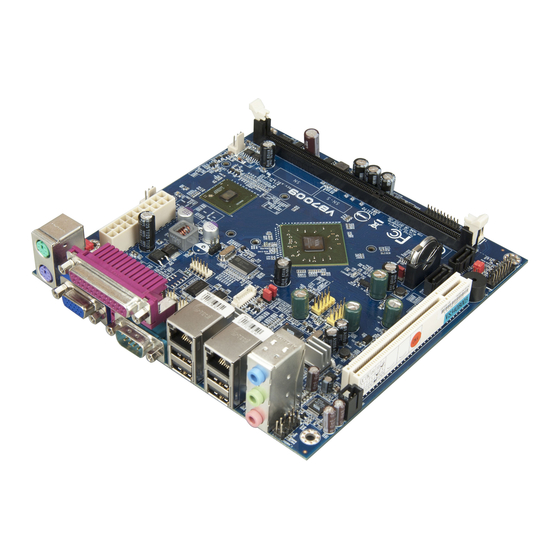
Page 23: Layout Diagram
: Layout diagram of the VB7009 VB7009 VB7009 VB7009 mainboard mainboard mainboard (top view) mainboard (top view) (top view) (top view) Notes: Notes: Notes: Notes: The additional COM pin headers labeled as “COM5” and “COM6” are available only in VB7009-12XC SKU. -
Page 24: Product Dimensions
Figure Figure 2 2 2 2 : Mounting holes and dimensions of the : Mounting holes and dimensions of the : Mounting holes and dimensions of the : Mounting holes and dimensions of the VB7009 VB7009 VB7009 VB7009 mainboard mainboard... -
Page 25: Height Distribution
Height: 32.00 mm Height: 33.00 mm Height: 35.00 mm Height: 34.60 mm Figure Figure 4 4 4 4 : Height distribution of the : Height distribution of the VB7009 VB7009 mainboard mainboard Figure Figure : Height distribution of the : Height distribution of the... -
Page 27: I/O Interface
2. 2. 2. 2. I/O Interface I/O Interface I/O Interface I/O Interface The VIA VB7009 has a wide selection of interfaces integrated into the board. It includes a selection of frequently used ports as part of the external I/O coastline. 2.1. External I/O Ports... -
Page 28: Ps/2 Port
VB7009 User Manual VB7009 User Manual VB7009 VB7009 User Manual User Manual 2.1.1. PS/2 Port The mainboard has two integrated PS/2 ports for keyboard and mouse. Each port is using the 6-pin Mini-DIN connector. The color purple is use for a PS/2 keyboard while the color green is use for a PS/2 mouse. - Page 29 VB7009 User Manual VB7009 User Manual VB7009 VB7009 User Manual User Manual VGA-SPD VGA_HS VGA_VS VGA-SPCLK Table Table 2 2 2 2 : VGA port pinout : VGA port pinout Table Table : VGA port pinout : VGA port pinout...
-
Page 30: Com Port
VB7009 User Manual VB7009 User Manual VB7009 VB7009 User Manual User Manual 2.1.3. COM Port The integrated 9-pin COM port uses a male DE-9 connector. The COM (COM1) port supports the RS-232 standard. The pinout of the COM port is shown below. -
Page 31: Parallel Port
VB7009 User Manual VB7009 User Manual VB7009 VB7009 User Manual User Manual 2.1.4. Parallel Port The integrated 25-pin parallel port uses a female DB-25 connector. A parallel port is a standard printer port that supports Enhanced Parallel Port (EPP) and Extended Capabilities Parallel Port (ECP) modes. -
Page 32: Rj45 Lan Port: Gigabit Ethernet
VB7009 User Manual VB7009 User Manual VB7009 VB7009 User Manual User Manual 2.1.5. RJ45 LAN port: Gigabit Ethernet The two integrated 8-pin Gigabit Ethernet ports are using an 8 Position 8 Contact (8P8C) receptacle connector (commonly referred to as RJ45). The Gigabit Ethernet ports are controlled by VIA Gigabit Ethernet controller. -
Page 33: Usb 2.0 Port
VB7009 User Manual VB7009 User Manual VB7009 VB7009 User Manual User Manual 2.1.6. USB 2.0 Port There are four integrated USB 2.0 ports located below the two RJ45 LAN port at the external I/O panel. The USB 2.0 interface port gives complete Plug and Play and hot swap capability for external devices and it complies with USB UHCI, rev. -
Page 34: Audio Ports
VB7009 User Manual VB7009 User Manual VB7009 VB7009 User Manual User Manual 2.1.7. Audio Ports There are three audio jack receptacles integrated into a single stack on the I/O coastline. Each receptacle can fit a 3.5 mm Tip Ring Sleeve (TRS) connector to enable connections to Line-Out Line-In, and MIC-in. -
Page 35: Onboard Connectors
VB7009 User Manual VB7009 User Manual VB7009 VB7009 User Manual User Manual 2.2. Onboard Connectors 2.2.1. ATX Power Connector The mainboard has a 20-pin ATX power connector onboard. The ATX power connector is labeled as “ATX_POWER1”. The pinout of the ATX power connector is shown below. -
Page 36: Cmos Battery Slot
VB7009 User Manual VB7009 User Manual VB7009 VB7009 User Manual User Manual 2.2.2. CMOS Battery Slot The mainboard is equipped with a CMOS battery slot, which is compatible with CR2032 coin batteries. The CMOS battery slot is labeled as “BAT2”. -
Page 37: Front Panel Pin Header
VB7009 User Manual VB7009 User Manual VB7009 VB7009 User Manual User Manual 2.2.3. Front Panel Pin Header The front panel pin header consists of 15 pins in a 16-pin block. Pin 15 is keyed. The front panel pin header is labeled as “F_PANEL1”. It provides access to system LEDs, power, reset, system speaker and HDD LED. -
Page 38: Front Audio Pin Header
VB7009 User Manual VB7009 User Manual VB7009 VB7009 User Manual User Manual 2.2.4. Front Audio Pin Header In addition to the TRS audio jacks on the external I/O coastline, the mainboard has a pin header for Line-Out and MIC-In. The pin header is labeled as “F_AUDIO1”. -
Page 39: Smbus Pin Header
VB7009 User Manual VB7009 User Manual VB7009 VB7009 User Manual User Manual 2.2.5. SMBus Pin Header The SMBus pin header consists of three pins that allow connecting the SMBus devices. Devices communicate with a SMBus host and/or other SMBus devices using the SMBus interface. -
Page 40: Cpu And System Fan Connectors
VB7009 User Manual VB7009 User Manual VB7009 VB7009 User Manual User Manual 2.2.6. CPU and System Fan Connectors There are two fan connectors on board: one for the CPU and one for the chassis. The fan connector for the CPU is labeled as “CPUFAN1” and the fan connector for the system is labeled as “SYSFAN1”. -
Page 41: Sata Connectors
VB7009 User Manual VB7009 User Manual VB7009 VB7009 User Manual User Manual 2.2.7. SATA Connectors The two SATA connectors on board can support up to 3 Gb/s transfer speeds, enabling fast data file transfer with independent DMA operation. The SATA connectors are labeled as “SATA1”... -
Page 42: Usb 2.0 Pin Headers
VB7009 User Manual VB7009 User Manual VB7009 VB7009 User Manual User Manual 2.2.8. USB 2.0 Pin Headers The mainboard has two USB 2.0 pin headers blocks that support up to four USB 2.0 ports. The pin header blocks are labeled as USB_4, and “USB_5”. The pinout of the USB pin headers are shown below. -
Page 43: Com Pin Headers
COM pin headers labeled as “COM2, COM3 and COM4” are available in VB7009-16 and VB7009-10E SKUs, while the additional “COM5” and “COM6” pin headers are offered only in VB7009-12XC SKU. All of the COM pin headers can support +5V or +12V. See page 39 for details on setting the voltage. -
Page 44: Ps/2 Keyboard And Mouse Pin Header
VB7009 User Manual VB7009 User Manual VB7009 VB7009 User Manual User Manual 2.2.10. PS/2 Keyboard and Mouse Pin Header The mainboard has a pin header for a PS/2 keyboard and mouse. The pin header is labeled as “JKB/MS1”. The pinout of the pin header is shown below. -
Page 45: Lvds Connector
VB7009 User Manual VB7009 User Manual VB7009 VB7009 User Manual User Manual 2.2.11. LVDS Connector The mainboard has one 40-pin LVDS connector on the bottom side. The LVDS connector is labeled as “PANEL_CONN1”. The pinout of the connector is shown below. - Page 46 VB7009 User Manual VB7009 User Manual VB7009 VB7009 User Manual User Manual -A3_L A3_L SPCLK1 SPD1 Table Table 19 19: LVDS connector pinout : LVDS connector pinout Table Table 19 19 : LVDS connector pinout : LVDS connector pinout...
-
Page 47: Inverter Connector
VB7009 User Manual VB7009 User Manual VB7009 VB7009 User Manual User Manual 2.2.12. Inverter Connector The mainboard has one Inverter connector on the bottom side. The Inverter connector is labeled as “INVERTER1”. The pinout of the connector is shown below. -
Page 48: Spdif Connector
VB7009 User Manual VB7009 User Manual VB7009 VB7009 User Manual User Manual 2.2.13. SPDIF Connector The mainboard has one 3-pin SPDIF (Sony Philips Digital Interface) connector. The SPDIF output provides digital audio to external speakers or compressed AC3 data to an external Dolby Digital Decoder. The connector is labeled as “SPDIF”. -
Page 49: Spi Pin Header
VB7009 User Manual VB7009 User Manual VB7009 VB7009 User Manual User Manual 2.2.14. SPI Pin Header The mainboard has one 8-pin SPI pin header. The SPI (Serial Peripheral Interface) pin-header is used to connect to the SPI BIOS programming fixture. -
Page 50: Lpc Pin Header
VB7009 User Manual VB7009 User Manual VB7009 VB7009 User Manual User Manual 2.2.15. LPC Pin Header The mainboard has one LPC pin header for connecting LPC devices. The pin header is labeled as “LPC1”. The pinout of the pin header is shown below. -
Page 51: Digital I/O Pin Header
VB7009 User Manual VB7009 User Manual VB7009 VB7009 User Manual User Manual 2.2.16. Digital I/O Pin Header The onboard Digital I/O pin header supports up to four GPO and four GPI signals. The pin header is labeled as “DIO1”. The pinout of the pin headers are shown below. -
Page 52: Temperature Sensor Pin Header
VB7009 User Manual VB7009 User Manual VB7009 VB7009 User Manual User Manual 2.2.17. Temperature Sensor Pin Header The mainboard supports a pin header (3-pin) that allows the connection of a temperature sensor cable for detecting the system’s internal air temperature. -
Page 53: Jumpers
VB7009 User Manual VB7009 User Manual VB7009 VB7009 User Manual User Manual 3. 3. 3. 3. Jumpers Jumpers Jumpers Jumpers 3.1. Clear CMOS Jumper The onboard CMOS RAM stores system configuration data and has an onboard battery power supply. To reset the CMOS settings, set the jumper on pins 2 and 3 while the system is off. - Page 54 VB7009 User Manual VB7009 User Manual VB7009 VB7009 User Manual User Manual Note: Note: Note: Note: Except when clearing the RTC RAM, never remove the cap from the CLEAR_CMOS jumper default position. Removing the cap will cause system boot failure. Avoid clearing the CMOS while the system...
-
Page 55: Com Voltage Select Jumpers
VB7009 User Manual VB7009 User Manual VB7009 VB7009 User Manual User Manual 3.2. COM Voltage Select Jumpers Each of the additional COM ports (available through the onboard COM pin headers, see page 27) can support both +5V and +12V. COM2 has its own pin header block. -
Page 56: Com3 And Com4 Voltage Select Jumper
VB7009 User Manual VB7009 User Manual VB7009 VB7009 User Manual User Manual 3.2.2. COM3 and COM4 Voltage Select Jumper The voltage for COM3 and COM4 is controlled by the jumper labeled as “J13”. Refer to Figure 32 for the location of the jumper. -
Page 57: Com5 And Com6 Voltage Select Jumper
VB7009 User Manual VB7009 User Manual VB7009 VB7009 User Manual User Manual 3.2.3. COM5 and COM6 Voltage Select Jumper The voltage for COM5 and COM6 is controlled by the jumper labeled as “J14”. Refer to Figure 33 for the location of the jumper. -
Page 58: Sata Dom Voltage Select Jumper
VB7009 User Manual VB7009 User Manual VB7009 VB7009 User Manual User Manual 3.3. SATA DOM Voltage Select Jumper The SATA connectors (see page 25) can be used to support Disk-on-Module (DOM) flash drives. When the jumpers are set, +5V will be delivered to the pin of the SATA connectors. -
Page 59: Panel Power Select Jumper
VB7009 User Manual VB7009 User Manual VB7009 VB7009 User Manual User Manual 3.4. Panel Power Select Jumper The mainboard has a jumper that controls the voltage delivered to the LVDS panel connector. The jumper is labeled as “PVDD1”. The jumper settings are shown below. -
Page 60: Backlight Power Select Jumper
VB7009 User Manual VB7009 User Manual VB7009 VB7009 User Manual User Manual 3.5. Backlight Power Select Jumper The mainboard has a jumper that controls the input voltage delivered to the LVDS inverter connector. The jumper is labeled as “IVDD_SEL1”. The jumper settings are shown below. -
Page 61: Expansion Slots Expansion Slots
VB7009 User Manual VB7009 User Manual VB7009 VB7009 User Manual User Manual 4. 4. 4. 4. Expansion Slots Expansion Slots Expansion Slots Expansion Slots 4.1. DDR3 Memory Slots The mainboard provide one DDR3 DIMM memory slot. The memory slot can accommodate up to 4 GB of 1066 MHz memory. -
Page 62: Installing A Memory Module
VB7009 User Manual VB7009 User Manual VB7009 VB7009 User Manual User Manual 4.1.1. Installing a Memory Module Step 1 Step 1 Step 1 Step 1 Disengage the locking mechanism at both ends of the DIMM slot by pressing the retaining clips outward. - Page 63 VB7009 User Manual VB7009 User Manual VB7009 VB7009 User Manual User Manual Step Step 3 3 3 3 Step Step Insert the DIMM memory module into the slot and push down at both ends until the locking clips lock the DIMM memory module into place.
-
Page 64: Removing A Memory Module
VB7009 User Manual VB7009 User Manual VB7009 VB7009 User Manual User Manual 4.1.2. Removing a Memory Module Step 1 Step 1 Step 1 Step 1 To disengage the locking clips, push outward the locking clips on both ends of memory slot. When the locking clips have cleared, the DIMM memory module will automatically pop up. -
Page 65: Pci Slot
VB7009 User Manual VB7009 User Manual VB7009 VB7009 User Manual User Manual 4.1.3. PCI Slot The onboard PCI slot, labeled as “PCI_SLOT1”, supports 5V 32-bit PCI cards. It is not compatible with PCI cards requiring 3.3V signaling. The location of the PCI slot is shown below. -
Page 67: Hardware Installation Hardware Installation
Hardware Installation 5.1. Installing into a Chassis The VB7009 can be fitted into any chassis that has the mounting holes for compatible with the standard Mini-ITX mounting hole locations. Additionally, the chassis must meet the minimum height requirements for specified areas of the mainboard. -
Page 68: Suggested Minimum Chassis Height
VB7009 User Manual VB7009 User Manual VB7009 VB7009 User Manual User Manual coastline should have a buffer of at least 5.00 mm. The two sides adjacent to the I/O coastline should have at least a 10.00 mm buffer. For the side that is close to the PCI slot, the buffer should be at least 100.00 mm if a riser card module will be used. -
Page 69: Suggested Keepout Areas
VB7009 User Manual VB7009 User Manual VB7009 VB7009 User Manual User Manual 5.1.3. Suggested keepout areas The figure below shows the areas of the mainboard that is highly suggested to leave unobstructed. Keep out area Figure Figure 45 45: Suggested keepout a... - Page 70 VB7009 User Manual VB7009 User Manual VB7009 VB7009 User Manual User Manual...
-
Page 71: Bios Setup Utility
VB7009 User Manual VB7009 User Manual VB7009 VB7009 User Manual User Manual 6. 6. 6. 6. BIOS Setup Utility BIOS Setup Utility BIOS Setup Utility BIOS Setup Utility 6.1. Entering the BIOS Setup Utility Power on the computer and press Delete... -
Page 72: Navigating The Bios Menus
VB7009 User Manual VB7009 User Manual VB7009 VB7009 User Manual User Manual 6.3. Navigating the BIOS Menus Left>/<Right Right> The main menu displays all the BIOS setup categories. Use the <Left Left Left Right Right and <Up Up>/<Down Down> arrow keys to select any item or sub-menu. Descriptions... -
Page 73: Main Menu
VB7009 User Manual VB7009 User Manual VB7009 VB7009 User Manual User Manual 6.5. Main Menu The Main Menu contains thirteen setup functions and two exit choices. Use arrow keys to select the items and press <Enter Enter> to accept or enter Sub-menu. -
Page 74: Power Management Setup
VB7009 User Manual VB7009 User Manual VB7009 VB7009 User Manual User Manual 6.5.5. Power Management Setup Use this menu to set onboard power management functions. 6.5.6. PnP/PCI Configurations Use this menu to set the PnP and PCI configurations. 6.5.7. PC Health Status This menu shows the PC health status. -
Page 75: Standard Cmos Features
VB7009 User Manual VB7009 User Manual VB7009 VB7009 User Manual User Manual 6.6. Standard CMOS Features Phoenix - AwardBIOS CMOS Setup Utility Standard CMOS Features Item Help Date (mm:dd:yy) Mon, Sept 26 2011 Time (hh:mm:ss) 3 : 17 : 8... -
Page 76: Ide Channels
VB7009 User Manual VB7009 User Manual VB7009 VB7009 User Manual User Manual 6.7. IDE Channels Channel 0 Master Channel 0 Master Channel 0 Master Channel 0 Master Phoenix - AwardBIOS CMOS Setup Utility IDE Channel 0 Master Item Help IDE HDD Auto-Detection... - Page 77 VB7009 User Manual VB7009 User Manual VB7009 VB7009 User Manual User Manual The specifications of your drive must match with the drive table. The hard disk will not work properly if you enter incorrect information in this category. Select “Auto”...
-
Page 78: Advanced Bios Features
VB7009 User Manual VB7009 User Manual VB7009 VB7009 User Manual User Manual 6.8. Advanced BIOS Features Phoenix - AwardBIOS CMOS Setup Utility Advanced BIOS Features CPU Feature [Press Enter] Item Help Hard Disk Boot Priority [Press Enter] Quick Power On Self Test... -
Page 79: Boot Other Device
VB7009 User Manual VB7009 User Manual VB7009 VB7009 User Manual User Manual VIA Networking Boot from network drive Disabled Disable the boot device sequence 6.8.3. Boot Other Device Enables the system to boot from alternate devices if the system fails to boot from the “First/Second/Third Boot Device”... -
Page 80: Cpu Feature
VB7009 User Manual VB7009 User Manual VB7009 VB7009 User Manual User Manual 6.9. CPU Feature Phoenix - AwardBIOS CMOS Setup Utility CPU Features Item Help Thermal Management [Thermal Monitor 3] PMON support [Disabled] Menu Level Thermal Monitor 3 Dynamic Ratio & VID... -
Page 81: Hard Disk Boot Priority
VB7009 User Manual VB7009 User Manual VB7009 VB7009 User Manual User Manual 6.10. Hard Disk Boot Priority Phoenix - AwardBIOS CMOS Setup Utility Hard Disk Boot Priority Item Help 1. Bootable Add-in Cards Menu Level Use < > or <... -
Page 82: Advanced Chipset Features
VB7009 User Manual VB7009 User Manual VB7009 VB7009 User Manual User Manual 6.11. Advanced Chipset Features Phoenix - AwardBIOS CMOS Setup Utility Advanced Chipset Features Item Help PCIE Bus Control [Press Enter] UMA & P2P Bridge Control [Press Enter] CPU & PCI Bus Control... -
Page 83: Pcie Bus Control
VB7009 User Manual VB7009 User Manual VB7009 VB7009 User Manual User Manual 6.12. PCIE Bus Control Phoenix - AwardBIOS CMOS Setup Utility PCIE Bus Control PCIE Root Port [Enable] Item Help PCIE Target Link Speed [Auto] PCIE PE0 Control [Enable]... -
Page 84: Pcie Aspm Function
VB7009 User Manual VB7009 User Manual VB7009 VB7009 User Manual User Manual 6.12.7. PCIE ASPM Function Settings: [Force Disable, Auto]... -
Page 85: Uma & P2P Bridge Control
VB7009 User Manual VB7009 User Manual VB7009 VB7009 User Manual User Manual 6.13. UMA & P2P Bridge Control Phoenix - AwardBIOS CMOS Setup Utility UMA & P2P Bridge Control UMA Enable [Enable] Item Help VGA Share Memory Size [256M] CPU Direct Access FB... -
Page 86: Select Display Device 2
VB7009 User Manual VB7009 User Manual VB7009 VB7009 User Manual User Manual 6.13.6. Select Display Device 2 This setting refers to the type of display device 2 being used with the system. Settings: [CRT, LCD] 6.13.7. Panel Type Key in a HEX number. -
Page 87: Cpu & Pci Bus Control
VB7009 User Manual VB7009 User Manual VB7009 VB7009 User Manual User Manual 6.14. CPU & PCI Bus Control Phoenix - AwardBIOS CMOS Setup Utility CPU & PCI Bus Control Item Help PCI Master 0 WS Write [Enabled] PCI Delay Transaction... -
Page 88: Integrated Peripherals
VB7009 User Manual VB7009 User Manual VB7009 VB7009 User Manual User Manual 6.15. Integrated Peripherals Phoenix - AwardBIOS CMOS Setup Utility Integrated Peripherals Item Help VIA OnChip IDE Device [Press Enter] VIA OnChip PCI Device [Press Enter] SuperIO Device [Press Enter]... -
Page 89: Via Onchip Ide Device
VB7009 User Manual VB7009 User Manual VB7009 VB7009 User Manual User Manual 6.16. VIA OnChip IDE Device Phoenix - AwardBIOS CMOS Setup Utility VIA OnChip IDE Device Item Help OnChip SATA [Enabled] Menu Level : Move Enter: Select +/-/PU/PD: Value... -
Page 90: Via Onchip Pci Device
VB7009 User Manual VB7009 User Manual VB7009 VB7009 User Manual User Manual 6.17. VIA OnChip PCI Device Phoenix - AwardBIOS CMOS Setup Utility VIA OnChip PCI Device Item Help Onboard PCIE LAN [Enabled] Hide D1F1 [Disabled] OnChip HDAC Device [Enabled]... -
Page 91: Superio Device
VB7009 User Manual VB7009 User Manual VB7009 VB7009 User Manual User Manual 6.18. SuperIO Device Phoenix - AwardBIOS CMOS Setup Utility SuperIO Device Item Help Onboard Serial Port 1 [3F8/IRQ4] Onboard Serial Port 2 [2F8/IRQ3] Onboard Serial Port 3 [3E8/IRQ4]... -
Page 92: Ecp Mode Use Dma
VB7009 User Manual VB7009 User Manual VB7009 VB7009 User Manual User Manual ECP mode. Choosing ECP + EPP will allow the onboard parallel port to support both the ECP and EPP modes simultaneously. Settings: [SPP, EPP, ECP, ECP + EPP] 6.18.4. -
Page 93: Usb Device Setting
VB7009 User Manual VB7009 User Manual VB7009 VB7009 User Manual User Manual 6.19. USB Device Setting Phoenix - AwardBIOS CMOS Setup Utility USB Device Setting Item Help USB 1.0 Controller [Enabled] USB 2.0 Controller [Enabled] USB Operation Mode [High Speed]... -
Page 94: Usb Mouse Function
VB7009 User Manual VB7009 User Manual VB7009 VB7009 User Manual User Manual Settings: [Disabled, Enabled] 6.19.5. USB Mouse Function Settings: [Disabled, Enabled] 6.19.6. USB Storage Function Enable or disable legacy support of USB mass storage. Settings: [Disabled, Enabled]... -
Page 95: Power Management Setup
VB7009 User Manual VB7009 User Manual VB7009 VB7009 User Manual User Manual 6.20. Power Management Setup Phoenix - AwardBIOS CMOS Setup Utility Power Management Setup Item Help EuP/ErP Lot6 [Disabled] ACPI Suspend Type [S1&S3] Soft-Off by PWRBTN [Instant-Off] Menu Level... -
Page 96: Soft-Off By Pwrbtn
VB7009 User Manual VB7009 User Manual VB7009 VB7009 User Manual User Manual wakeup-capable devices. The system context is saved to main memory, and context is restored from the memory when a "wakeup" event occurs. S1 & S3 Depends on the OS to select S1 or S3. -
Page 97: Wdrt Count
VB7009 User Manual VB7009 User Manual VB7009 VB7009 User Manual User Manual 6.20.9. WDRT Count Key in a DEC number. Settings: [Min = 0, Max = 1023]... -
Page 98: Wakeup Event Detect
VB7009 User Manual VB7009 User Manual VB7009 VB7009 User Manual User Manual 6.21. Wakeup Event Detect Phoenix - AwardBIOS CMOS Setup Utility Wakeup Event Detect Item Help PS2KB Wakeup Select [Hot Key] PS2KB Wakeup Key Select [Any Key] PS2MS Wakeup Key Select... -
Page 99: Ps2 Keyboard Power On
VB7009 User Manual VB7009 User Manual VB7009 VB7009 User Manual User Manual 6.21.4. PS2 Keyboard Power ON Settings: [Disabled, Enabled] 6.21.5. PS2 Mouse Power ON Settings: [Disabled, Enabled] 6.21.6. RTC Alarm Resume Set a scheduled time and/or date to automatically power on the system. -
Page 100: Pnp/Pci Configurations
VB7009 User Manual VB7009 User Manual VB7009 VB7009 User Manual User Manual 6.22. PnP/PCI Configurations Phoenix - AwardBIOS CMOS Setup Utility PnP/PCI Configurations Item Help Init Display First [PCIEx] Resources Controlled By [Auto(ESCD)] Menu Level IRQ Resources Press Enter : Move... -
Page 101: Pc Health Status
VB7009 User Manual VB7009 User Manual VB7009 VB7009 User Manual User Manual 6.23 PC Health Status Phoenix - AwardBIOS CMOS Setup Utility PC Health Status VCore 1.000V Item Help +3.3V 3.200V 5.100V Menu Level +12V 11.880V SYSTEM Temp. 30°C CPU FAN... -
Page 102: Frequency/Voltage Control
VB7009 User Manual VB7009 User Manual VB7009 VB7009 User Manual User Manual 6.24 Frequency/Voltage Control Phoenix - AwardBIOS CMOS Setup Utility Frequency/Voltage Control Current FSB Frequency 100 MHz Item Help Current DRAM Frequency 533 MHz DRAM Clock [By SPD] Menu Level Spread Spectrum [+/-0.1%]... -
Page 103: Load Optimized Defaults
VB7009 User Manual VB7009 User Manual VB7009 VB7009 User Manual User Manual 6.25 Load Optimized Defaults Phoenix - AwardBIOS CMOS Setup Utility Standard CMOS Features Frequency/Voltage Control Advanced BIOS Features Load Optimized Defaults Advanced Chipset Features Set Supervisor Password Integrated Peripherals... -
Page 104: Set Supervisor/User Password
VB7009 User Manual VB7009 User Manual VB7009 VB7009 User Manual User Manual 6.26 Set Supervisor/User Password Phoenix - AwardBIOS CMOS Setup Utility Standard CMOS Features Frequency/Voltage Control Advanced BIOS Features Load Optimized Defaults Advanced Chipset Features Set Supervisor Password Integrated Peripherals... - Page 105 VB7009 User Manual VB7009 User Manual VB7009 VB7009 User Manual User Manual Additionally, when a password is enabled, the BIOS can be set to request the password each time the system is booted. This would prevent unauthorized use of the system. See “Security Option” in the “Advanced BIOS Features”...
-
Page 106: Save & Exit Setup
VB7009 User Manual VB7009 User Manual VB7009 VB7009 User Manual User Manual 6.27 Save & Exit Setup Phoenix - AwardBIOS CMOS Setup Utility Standard CMOS Features Frequency/Voltage Control Advanced BIOS Features Load Optimized Defaults Advanced Chipset Features Set Supervisor Password... -
Page 107: Exit Without Saving
VB7009 User Manual VB7009 User Manual VB7009 VB7009 User Manual User Manual 6.28 Exit Without Saving Phoenix - AwardBIOS CMOS Setup Utility Standard CMOS Features Frequency/Voltage Control Advanced BIOS Features Load Optimized Defaults Advanced Chipset Features Set Supervisor Password Integrated Peripherals... -
Page 109: Driver Installation
For embedded operating systems, the related drivers can be found in the VIA Embedded website at www.viaembedded.com. 7.2 Linux Driver Support The VIA VB7009 mainboard is highly compatible with many Linux distributions. Support and drivers are provided through various methods including: Drivers provided by VIA Using a driver built into a distribution package Visiting www.viaembedded.com for the latest updated drivers... -
Page 111: Appendix A. Power Consumption Report
Power Consumption Report Power Consumption Report Power Consumption Report Power Consumption Report Power consumption tests were performed on the VIA VB7009. The following tables represent the breakdown of the voltage, amp and wattage values while running common system applications. A.1. VB7009-16 The tests were performed based on the following additional components: ®... -
Page 112: S3 Status - Windows 7 Sleep
VB7009 User Manual VB7009 User Manual VB7009 VB7009 User Manual User Manual A.1.2. S3 Status – Windows 7 Sleep Power Plane Power Plane Power Plane Power Plane Volts Volts Volts Volts Amperes Amperes Amperes Amperes Watts Watts Watts Watts +3.3V -0.019... -
Page 113: Functional Test - Run Passmark Burnin Test 6.0
VB7009 User Manual VB7009 User Manual VB7009 VB7009 User Manual User Manual +5VSB 4.786 0.227 1.086 +12V 11.884 0.065 0.772 Total Power 26.475 Consumption A.1.6. Functional Test – Run Passmark BurnIn test 6.0 Power Plane Power Plane Power Plane Power Plane... -
Page 114: Network Access
VB7009 User Manual VB7009 User Manual VB7009 VB7009 User Manual User Manual A.1.8. Network Access <Dual LAN> – Gigabit Ethernet File Transmitting Power Plane Power Plane Power Plane Power Plane Volts Volts Volts Volts Amperes Amperes Amperes Amperes Watts Watts...- Gigabit Ethernet File Transmitting -
Page 115: Vb7009-10E
VB7009 User Manual VB7009 User Manual VB7009 VB7009 User Manual User Manual A.2. VB7009-10E The tests were performed based on the following additional components: ® CPU: : : : VIA C7 1.0 GHz Chipset Chipset: : : : VX900 Chipset... -
Page 116: Mp3 Playback - Windows Media Player10
VB7009 User Manual VB7009 User Manual VB7009 VB7009 User Manual User Manual A.2.3. MP3 Playback – Windows Media Player10 Power Plane Power Plane Power Plane Power Plane Volts Volts Volts Volts Amperes Amperes Amperes Amperes Watts Watts Watts Watts +3.3V 3.233... -
Page 117: Functional Test - Run Passmark Burnin Test 6.0
VB7009 User Manual VB7009 User Manual VB7009 VB7009 User Manual User Manual A.2.6. Functional Test – Run Passmark BurnIn test 6.0 Power Plane Power Plane Power Plane Power Plane V V V V olts olts olts olts Amperes Amperes Amperes... -
Page 118: Vb7009-12Xc
VB7009 User Manual VB7009 User Manual VB7009 VB7009 User Manual User Manual A.3. VB7009-12XC The tests were performed based on the following additional components: CPU: : : : VIA NanoX2 1.2 GHz Chipset Chipset: : : : VX900 Chipset Chipset... -
Page 119: Mp3 Playback - Windows Media Player10
VB7009 User Manual VB7009 User Manual VB7009 VB7009 User Manual User Manual A.3.3. MP3 Playback – Windows Media Player10 Power Plane Power Plane Volts Volts Amperes Amperes Watts Watts Power Plane Power Plane Volts Volts Amperes Amperes Watts Watts +3.3V 2.998... -
Page 120: Functional Test - Run Passmark Burnin Test 6.0
VB7009 User Manual VB7009 User Manual VB7009 VB7009 User Manual User Manual A.3.6. Functional Test – Run Passmark BurnIn test 6.0 Power Plane Power Plane Power Plane Power Plane Volts Volts Volts Volts Amperes Amperes Amperes Amperes Watts Watts Watts Watts +3.3V... -
Page 121: S5 Status - Windows 7 Shut Down
VB7009 User Manual VB7009 User Manual VB7009 VB7009 User Manual User Manual A.3.9. S5 Status – Windows 7 Shut down Power Plane Power Plane Power Plane Power Plane Volts Volts Volts Volts Amperes Amperes Amperes Amperes Watts Watts Watts Watts +3.3V... -
Page 123: Appendix B. Mating Connector Vendor Lists Appendix B. Mating Connector Vendor Lists
SSW Series 2214R-XXG-85 Table Table Table Table 33 33 33 33: VB700 : VB700 : VB7009 9 9 9 m m m mating connector vendor lists : VB700 ating connector vendor lists ating connector vendor lists ating connector vendor lists... - Page 124 Taiwan Headquarters Europe 1F, 531 Zhong-Zheng Road 940 Mission Court In den Dauen 6 Xindian District, New Taipei City 231, Fremont, CA 94539 53117 Bonn Taiwan Germany TEL: 886.2.2218.5452 TEL: 1.510.683.3300 TEL: 49.228.688565.0 FAX: 886.2.2218.5453 FAX: 1.510.687.4654 FAX: 49.228.688565.19 Email: embedded@via.com.tw Email: embedded@viatech.com Email: embedded@via-tech.de China...
Need help?
Do you have a question about the VB7009 and is the answer not in the manual?
Questions and answers