Table of Contents
Advertisement
Quick Links
I n s t r u c t i o n M a n u a l
Modero X-Series
G4 Touch Panels
MXT/D-2000-PAN - 20.3" Modero X Series Panoramic Touch Panels
MXT/D-1900-PAN - 19.4" Modero X Series Panoramic Touch Panels
MXT/D-1000-PAN - 10.1" Modero X Series Touch Panels
MXT/D-701-PAN - 7" Modero X Series Touch Panels
MXD-430 - 4.3" Modero X Series Wall Mount Touch Panel
L a s t R e v is e d : 9 / 1 9 / 2 0 1 4
M o d e r o X S e r i e s G 4 T o u c h P a n e l s
Advertisement
Table of Contents

Related Manuals for AMX MXT/D-2000-PAN


Summary of Contents for AMX MXT/D-2000-PAN
- Page 1 I n s t r u c t i o n M a n u a l Modero X-Series G4 Touch Panels MXT/D-2000-PAN - 20.3" Modero X Series Panoramic Touch Panels MXT/D-1900-PAN - 19.4" Modero X Series Panoramic Touch Panels MXT/D-1000-PAN - 10.1" Modero X Series Touch Panels MXT/D-701-PAN - 7"...
- Page 2 AMX is not responsible for products returned without a valid RMA number. AMX is not liable for any damages caused by its products or for the failure of its products to perform. This includes any lost profits, lost savings, incidental damages, or consequential damages.
-
Page 3: Table Of Contents
Table of Contents Table of Contents Modero X Series G4 Touch Panels ..............1 Overview ........................1 Sleep Button ......................2 Configuration and Programming ................2 Accessing the Settings Menu ..................3 Using the Settings Pages....................3 Bluetooth Support ....................3 NFC Support...................... - Page 4 Table of Contents MXD-430 - 4.3” X Series Panels ...............37 MXD-430 4.3" Modero X Series Wall/Flush Mount Touch Panel ......37 MXD-430 Specifications ....................37 Installing Tabletop (MXT) Panels ..............41 MXT-2000XL-PAN / MXT-1900L-PAN ..............41 Connector Locations - MXT-2000XL-PAN / MXT-1900L-PAN ........41 MXT-1000 / MXT-700 .....................
- Page 5 Removing an MXD-430 from Its Backbox ................. 74 Upgrading Firmware ..................75 Overview ........................ 75 Downloading Firmware Updates From www.amx.com ........... 75 Upgrading Firmware via USB Flash Drive ............... 75 Load the Firmware on a USB Flash Drive ..............75 Transfer the Firmware File From the Flash Drive to the Touch Panel......76 Upgrading from Previous Firmware ................
- Page 6 Table of Contents Modero X® Series G4 Touch Panels Instruction Manual...
-
Page 7: Modero X Series G4 Touch Panels
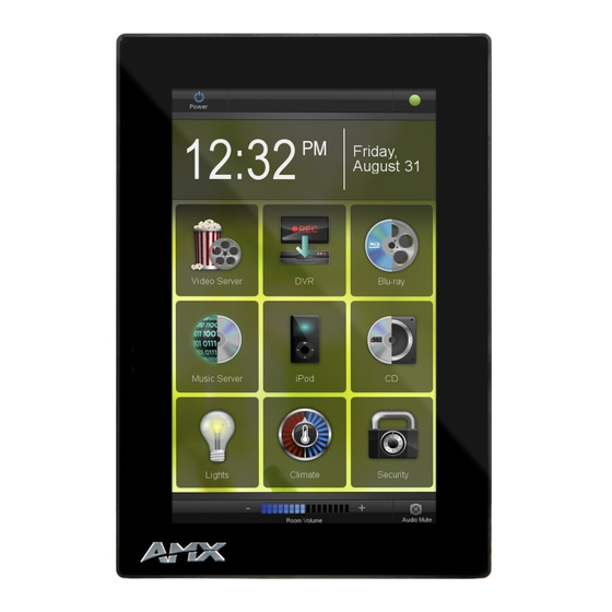
Modero X Series G4 Touch Panels Modero X Series G4 Touch Panels Overview This new generation of G4 touch panels is built for usability offering edge-to-edge capacitive touch glass with multi- touch capabilities. It features advanced technology empowering users to operate AV equipment seamlessly, while providing the ultimate in audio and video quality. -
Page 8: Sleep Button
Modero X Series G4 Touch Panels Modero X Series Touch Panels (Cont.) Name Description X Series - No Comm Panels: The X Series - No Comm Panels do not have camera, microphone, NFC or Bluetooth capability. Otherwise, they have all of the functionality of the standard Modero X Series panels. MXT-2000XL-PAN-NC FG5968-32 No Comm 20.3"... -
Page 9: Accessing The Settings Menu
Scroll down to reach all functions on a given page. Information on the Settings menu, panel configuration, and programming is included in the Modero X Series G4 Programming Guide, available at www.amx.com. Programming the Modero X Series G4 touch panels require the use of the latest versions of NetLinx Studio and TPDesign4, both available to download at www.amx.com. -
Page 10: Active Video Windows - Limitations
Modero X Series G4 Touch Panels The maximum range for the NFC antenna is 0.5" (12.7 mm), but the typical usage range is 0.25" (6.35 mm). The antenna itself is accessible from the front of the panel, 3.25" (82.55 mm) from the left corner of the panel and 0.375"... -
Page 11: Preview Mode And Normal Mode
The ^PIC Send Command stops either mode of Picture View, or starts Preview Mode. For more information, please refer to the Modero X/S Series G4 Touch Panels Programming Guide, available at www.amx.com. All images must be in JPEG format. PNG and other image formats cannot be viewed through Picture View. -
Page 12: Cleaning The Touch Overlay And Case
Modero X Series G4 Touch Panels Cleaning the Touch Overlay and Case Modero X Series touch panels come with the MXA-CLK Modero X Series Cleaning Kit (FG5968-16), which may be used to clean fingerprints and dirt from the device. This kit comes with cleaning cloths and a bottle of cleaning fluid specifically for use with the device. -
Page 13: Mxt/D-2000Xl-Pan - 20.3" X Series Panels
• Standby: 3.10 W (12 VDC, 0.3 A) • Start-Up Inrush Current: 4.0 A for 80 µsec EXTERNAL POWER Requires one of these AMX power sources (not included): SUPPLY REQUIRED • PSN4.4 Power Supply, 4.4 A, 3.5 mm Phoenix, 13.5 VDC (FG423-45) •... - Page 14 AMX G4: G4 enhanced feature set supporting multi-touch and gestures, scrolling, transitions - See TPD4 Operations Guide for more information EMBEDDED • Remote Management: VNC Server, G4 Web Control, AMX Resource Management Suite APPLICATIONS • Video Conferencing: Panel-to-panel and video chat •...
- Page 15 MXT/D-2000XL-PAN - 20.3" X Series Panels MXT-2000XL-PAN Specifications (Cont.) FRONT PANEL • Light Sensor: Photosensitive light detector for automatic adjustment of the panel brightness COMPONENTS • Proximity Detector: Max range = ~3', typ range = ~1', FOV = ~10 degrees •...
-
Page 16: Mxd-2000Xl-Pan (Wall Mount-Landscape/Portrait)
• Standby: 3.10 W (12 VDC, 0.3 A) • Start-Up Inrush Current: 4.0 A for 80 µsec EXTERNAL POWER Requires one of these AMX power sources (not included): SUPPLY REQUIRED • PSN4.4 Power Supply, 4.4 A, 3.5 mm Phoenix, 13.5 VDC (FG423-45) •... - Page 17 MXT/D-2000XL-PAN - 20.3" X Series Panels MXD-2000XL-PAN Specifications (Cont.) CERTIFICATIONS • FCC Part 15 Class B • CE EN 55022 • CE EN 55024 • CE EN 60950-1 • IEC 60950-1 • C-Tick CISPR 22 Class B • IC • UL 60950-1 •...
- Page 18 AMX G4: G4 enhanced feature set supporting multi-touch and gestures, scrolling, transitions - See TPD4 Operations Guide for more information EMBEDDED APPLICATIONS • Remote Management: VNC Server, G4 Web Control, AMX Resource Management Suite • Video Conferencing: Panel-to-panel and video chat (portrait wall mount receives video and returns audio) •...
- Page 19 MXT/D-2000XL-PAN - 20.3" X Series Panels MXD-2000XL-PAN Specifications (Cont.) INCLUDED ACCESSORIES • Locking 2-pin Phoenix mate (41-0002-SA) • MXA-USB-C, USB Port Cover Kit, Modero X Series Touch Panel (FG5968-18) • MXA-CLK, Modero X Series Cleaning Kit (FG5968-16) • Installation Template 20.3" (68-5968-01) OPTIONAL ACCESSORIES •...
- Page 20 MXT/D-2000XL-PAN - 20.3" X Series Panels Modero X® Series G4 Touch Panels Instruction Manual...
-
Page 21: Mxt/D-1900L-Pan - 19.4" X Series Panels
• Standby: 3.10 W (12 VDC, 0.3 A) • Start-Up Inrush Current: 4.0 A for 80 µsec EXTERNAL POWER Requires one of these AMX power sources (not included): SUPPLY REQUIRED • PSN4.4 Power Supply, 4.4 A, 3.5 mm Phoenix, 13.5 VDC (FG423-45) •... - Page 22 • Intercom: Full Duplex VoIP, SIP v2.0 (supported with AMX-CSG) GRAPHICS ENGINE AMX G4: G4 enhanced feature set supporting multi-touch and gestures, scrolling, transitions - See TPD4 Operations Guide for more information Modero X® Series G4 Touch Panels Instruction Manual...
- Page 23 MXT/D-1900L-PAN - 19.4" X Series Panels MXT-1900L-PAN Specifications (Cont.) EMBEDDED • Remote Management: VNC Server, G4 Web Control, AMX Resource Management Suite APPLICATIONS • Video Conferencing: Panel-to-panel and video chat • Conferencing: Audio (Full Duplex Intercom) FRONT PANEL • Light Sensor: Photosensitive light detector for automatic adjustment of the panel brightness COMPONENTS •...
-
Page 24: Mxd-1900L-Pan (Wall Mount-Landscape/Portrait)
• Standby: 3.10 W (12 VDC, 0.3 A) • Start-Up Inrush Current: 4.0 A for 80 µsec EXTERNAL POWER Requires one of these AMX power sources (not included): SUPPLY REQUIRED • PSN4.4 Power Supply, 4.4 A, 3.5 mm Phoenix, 13.5 VDC (FG423-45) •... - Page 25 MXT/D-1900L-PAN - 19.4" X Series Panels MXD-1900L-PAN Specifications (Cont.) CERTIFICATIONS • FCC Part 15 Class B • CE EN 55022 • CE EN 55024 • CE EN 60950-1 • IEC 60950-1 • C-Tick CISPR 22 Class B • IC • UL 60950-1 •...
- Page 26 • File Formats: WAV, MP3 (as part of touch panel file only - no USB storage) • Intercom: Full Duplex VoIP, SIP v2.0 (supported with AMX-CSG) GRAPHICS ENGINE AMX G4: G4 enhanced feature set supporting multi-touch and gestures, scrolling, transitions - See TPD4 Operations Guide for more information EMBEDDED •...
- Page 27 MXT/D-1900L-PAN - 19.4" X Series Panels MXD-1900L-PAN Specifications (Cont.) INCLUDED ACCESSORIES • Locking 2-pin Phoenix mate (41-0002-SA) • MXA-USB-C, USB Port Cover Kit, Modero X Series Touch Panel (FG5968-18) • MXA-CLK, Modero X Series Cleaning Kit (FG5968-16) • Wall Template 19" (68-5968-02) OPTIONAL ACCESSORIES •...
- Page 28 MXT/D-1900L-PAN - 19.4" X Series Panels Modero X® Series G4 Touch Panels Instruction Manual...
-
Page 29: Mxt/D-1000 - 10.1" X Series Panels
• Shutdown: 1 W • Start-Up Inrush Current: Not applicable due to PoE standard EXTERNAL POWER Optimal performance requires use of one of the following AMX PoE power supplies (not SUPPLY REQUIRED included): • PS-POE-AF-TC, PoE Injector, 802.3AF Compliant (FG423-83) •... - Page 30 • Intercom: Full Duplex VoIP, SIP v2.0 (supported with AMX-CSG) GRAPHICS ENGINE AMX G4: G4 enhanced feature set supporting multi-touch and gestures, scrolling, transitions - See TPD4 Operations Guide for more information Modero X® Series G4 Touch Panels Instruction Manual...
-
Page 31: Touch Panel Aspect Ratio
MXT/D-1000 - 10.1" X Series Panels MXT-1000 Specifications (Cont.) EMBEDDED • Remote Management: VNC Server, G4 Web Control, AMX Resource Management APPLICATIONS Suite • Video Conferencing: Panel-to-panel and video chat • Audio Conferencing: Audio (Full Duplex Intercom) FRONT PANEL • Light Sensor: Photosensitive light detector for automatic adjustment of the panel... -
Page 32: Mxd-1000 (Wall-Mount - Landscape/Portrait)
• Shutdown: 1 W • Start-Up Inrush Current: Not applicable due to PoE standard EXTERNAL POWER Optimal performance requires use of one of the following AMX PoE power supplies (not SUPPLY REQUIRED included): • PS-POE-AF-TC, PoE Injector, 802.3AF Compliant (FG423-83) •... - Page 33 MXT/D-1000 - 10.1" X Series Panels MXD-1000 Specifications (Cont.) TOUCH SCREEN DISPLAY • Display Type: TFT Active Matrix Color LCD with In-plane Switching Technology (IPS) • Display Size (WH) Landscape: 9.9" x 6.7" (252 mm x 170 mm), 12.0" (304 mm) diagonal Portrait: 6.7"...
- Page 34 • File Formats: WAV, MP3 (as part of touch panel file only - no USB storage) • Intercom: Full Duplex VoIP, SIP v2.0 (supported with AMX-CSG) GRAPHICS ENGINE AMX G4: G4 enhanced feature set supporting multi-touch and gestures, scrolling, transitions - See TPD4 Operations Guide for more information EMBEDDED •...
-
Page 35: Touch Panel Aspect Ratio
MXT/D-1000 - 10.1" X Series Panels Touch Panel Aspect Ratio While the touch panel screen physical dimensions fall between 16:9 and 16:10, any incoming video stream can be scaled to 16:9 if needed. This may lead to some letter boxing around the video in some cases. Modero X®... - Page 36 MXT/D-1000 - 10.1" X Series Panels Modero X® Series G4 Touch Panels Instruction Manual...
-
Page 37: Mxt/D-700 - 7" X Series Panels
• Shutdown: 1 W • Start-Up Inrush Current: Not applicable due to PoE standard EXTERNAL POWER Optimal performance requires use of one of the following AMX PoE power supplies (not SUPPLY REQUIRED included): • PS-POE-AF-TC, PoE Injector, 802.3AF Compliant (FG423-83) •... - Page 38 • File Formats: WAV, MP3 (as part of touch panel file only - no USB storage) • Intercom: Full Duplex VoIP, SIP v2.0 (supported with AMX-CSG) GRAPHICS ENGINE AMX G4: G4 enhanced feature set supporting multi-touch and gestures, scrolling, transitions - See TPD4 Operations Guide for more information EMBEDDED •...
-
Page 39: Touch Panel Aspect Ratio
MXT/D-700 - 7" X Series Panels MXT-700 Specifications (Cont.) FRONT PANEL • Light Sensor: Photosensitive light detector for automatic adjustment of the panel COMPONENTS brightness • Proximity Detector: Max range = ~3', typ range = ~1', FOV = ~10 degrees •... -
Page 40: Mxd-700 (Wall-Mount - Landscape/Portrait)
• Shutdown: 1 W • Start-Up Inrush Current: Not applicable due to PoE standard EXTERNAL POWER Optimal performance requires use of one of the following AMX PoE power supplies (not SUPPLY REQUIRED included): • PS-POE-AF-TC, PoE Injector, 802.3AF Compliant (FG423-83) •... - Page 41 • Intercom: Full Duplex VoIP, SIP v2.0 (supported with AMX-CSG) GRAPHICS ENGINE AMX G4: G4 enhanced feature set supporting multi-touch and gestures, scrolling, transitions - See TPD4 Operations Guide for more information Modero X® Series G4 Touch Panels Instruction Manual...
-
Page 42: Touch Panel Aspect Ratio
MXT/D-700 - 7" X Series Panels MXD-700 Specifications (Cont.) EMBEDDED • Remote Management: VNC Server, G4 Web Control, AMX Resource Management APPLICATIONS Suite • Video Conferencing: Panel-to-panel and video chat (the MXD-700 receives video and returns audio) • Audio Conferencing: Audio (Full Duplex Intercom) FRONT PANEL •... -
Page 43: Mxd-430 - 4.3" X Series Panels
• Shutdown: 1.9 W • Start-Up Inrush Current: Not applicable due to PoE standard EXTERNAL POWER Optimal performance requires use of one of the following AMX PoE power supplies (not SUPPLY REQUIRED included): • PS-POE-AF-TC, PoE Injector, 802.3AF Compliant (FG423-83) •... - Page 44 • File Formats: WAV, MP3 (as part of touch panel file only - no USB storage) • Intercom: Full Duplex VoIP, SIP v2.0 (supported with AMX-CSG) GRAPHICS ENGINE AMX G4: G4 enhanced feature set supporting multi-touch and gestures, scrolling, transitions - See TPD4 Operations Guide for more information. EMBEDDED •...
- Page 45 MXD-430 - 4.3” X Series Panels MXD-430 Specifications (Cont.) FRONT PANEL • Light Sensor: Photosensitive light detector for automatic adjustment of the panel COMPONENTS brightness • Proximity Detector: Max range = ~3', typ range = ~1', FOV = ~10 degrees •...
- Page 46 MXD-430 - 4.3” X Series Panels Modero X® Series G4 Touch Panels Instruction Manual...
-
Page 47: Installing Tabletop (Mxt) Panels
MXT-2000XL-PAN MXT-1900L-PAN are available to download from www.amx.com. Connector Locations - MXT-2000XL-PAN / MXT-1900L-PAN Two Type A USB ports are located on the rear right corner of the panel (FIG. 15). USB peripherals (i.e. mouse, keyboard) may be connected to either of the two USB ports on the rear of the device. Note that FIG. 15 shows the MXT-1900L-PAN, but the USB ports are in a similar location on the MXT-2000XL-PAN. -
Page 48: Mxt-1000 / Mxt-700
Detailed specifications drawings for the MXT-1000 MXT-700 are available to download from www.amx.com. Connector Locations - MXT-1000/MXT-700 Two Type A USB ports are located on the rear right corner of the panel (FIG. 18). USB peripherals (i.e. mouse, keyboard) may be connected to either of the two USB ports on the rear of the device. Updates to the device’s firmware can also made via the USB ports (see Upgrading Firmware via USB Flash Drive on page 41 for details). -
Page 49: Power Via Poe
Power via PoE Power for the MXT-1000 and MXT-700 is supplied via PoE (Power Over Ethernet ), utilizing an AMX-certified, capacitive touch-compliant PoE injector such as the PS-POE-AT High Power PoE Injector (FG423-81) or other approved AMX PoE power source. - Page 50 Installing Tabletop (MXT) Panels Modero X® Series G4 Touch Panels Instruction Manual...
-
Page 51: Installing Wall-Mount (Mxd) Panels
FIG. 21 shows an AMX device installed in a wall with a filled volume (such as with insulation or concrete), as well as with a closed volume (such as between studs in an otherwise finished wall). The diagram shows how heat generated by the device or other devices may have no way to escape, and may build up to levels that may affect device operation. -
Page 52: Installation Recommendations
MXD-2000XL-PAN MXD-1900L-PAN (portrait and landscape) are available to download from www.amx.com. MXD-2000XL-PAN and MXD-1900L-PAN panels may be installed directly into a solid surface, using either solid surface screws or the included locking tabs for different mounting options. Once installed, the panel is contained within a clear outer housing known as the Backbox (FIG. 23). This Backbox is removed when installing the device into a wall or when using the optional Rough-In Box accessory (FG039-15). -
Page 53: Installing The Mxd-2000Xl-Pan / Mxd-1900L-Pan Into A Wall
Installing Wall-Mount (MXD) Panels Installing the MXD-2000XL-PAN / MXD-1900L-PAN Into a Wall The Backbox has four locking tabs (two on top and two on bottom) to lock the Backbox to the wall (FIG. 24). Note that FIG. 24 shows the MXD-1900L-PAN, but the locking tabs are in a similar location on the MXT-2000XL-PAN. Locking tabs (X4) Backbox knockouts (X8) Backbox... -
Page 54: Mxd-2000Xl-Pan Dimensions
MXD-2000XL-PAN Dimensions FIG. 25 provides dimensions for the MXD-2000XL-PAN: Notes: Dimensions in parenthesis are in millimeters Additional detailed installation and product drawings are available to view/download at www.amx.com FIG. 25 MXD-2000XL-PAN - Dimensions Modero X® Series G4 Touch Panels Instruction Manual... -
Page 55: Mxd-1900L-Pan Dimensions
FIG. 26 provides dimensions for the MXD-1900L-PAN: Notes: Dimensions in parenthesis are in millimeters Additional detailed installation and product drawings are available to view/download at www.amx.com FIG. 26 MXD-1900L-PAN - Dimensions In order to ensure a stable installation, the thickness of the wall material must be a minimum of .50 inches (1.27cm) and a maximum of .875 inches (2.22cm). -
Page 56: Installing The Backbox
Portrait panels, except for the vertical orientation. Additional detailed installation and product drawings (for both Landscape and Portrait versions are available to view/download at www.amx.com FIG. 28 MXD-2000XL-PAN-L Installation Dimensions (side view) Modero X® Series G4 Touch Panels Instruction Manual... -
Page 57: Mxd-1900L-Pan Installation Dimensions
Portrait panels, except for the vertical orientation. Additional detailed installation and product drawings (for both Landscape and Portrait versions are available to view/download at www.amx.com FIG. 30 MXD-1900L-PAN-L Installation Dimensions (side view) Since the cutout for the Backbox is off-center from the edges of the touch panel, use the included Installation Template to ensure proper placement. - Page 58 Routing As Needed placement (optional) Note: Additional detailed installation and product drawings are available to view/download at www.amx.com FIG. 31 MXD-1900L-PAN Backbox installation (Landscape) Remove any knockouts as needed on either long dimension of the Backbox to facilitate incoming wiring and pull the wiring through the resultant holes.
- Page 59 Installing Wall-Mount (MXD) Panels Not all of the tabs must be extended to lock the Backbox in place, but extending a minimum of the top and bottom tabs is highly recommended. Apply enough pressure to the screw head to keep the box flush with the wall: this ensures that the locking tabs will tighten up against the inside of the wall.
-
Page 60: Power Via 12 Vdc
6X 4-40 X 1/4" LONG FLAT HEAD TORQUE TO 5±.2 IN LBS Note: Additional detailed installation and product drawings are available to view/download at www.amx.com FIG. 33 MXD-1900L-PAN installation (Landscape) When installing the panel, do NOT press on or near the center of the panel. Too much stress at the center may damage the touch screen surface. -
Page 61: Wiring A 12Vdc Power Connection
Installing Wall-Mount (MXD) Panels Wiring a 12VDC Power Connection To use the 2-pin 3.5 mm captive wire connector with a 12 VDC-compliant power supply, the incoming PWR and GND wires from the external source must be connected to their corresponding locations on the connector (FIG. 34). The connector uses locking screws to insure a connection to the device, so make sure to insert and tighten the screws before applying power. -
Page 62: Mxd-1000/ Mxd-700 Installation
Backbox. Be careful not to pull on the cables or connectors. To reattach the panel to its Backbox, repeat the installation procedure. For further information, refer to the video available at www.amx.com (go to Newsroom > Videos > Touch Panels). -
Page 63: Installing The Mxd-1000 / Mxd-700 Into A Wall
Installing Wall-Mount (MXD) Panels Installing the MXD-1000 / MXD-700 Into a Wall The Backbox has locking tabs to lock the Backbox to the wall - there are four on the MXD-1000 and two on the MXD-700 (FIG. 37). Locking tabs (X4) Backbox knockouts (X4) Backbox knockouts (X4) Locking tabs (X2) -
Page 64: Mxd-1000 Dimensions
MXD-1000 Dimensions FIG. 38 provides dimensions for the MXD-1000: Notes: Dimensions in parenthesis are in millimeters Additional detailed installation and product drawings are available to view/download at www.amx.com FIG. 38 MXD-1000 - Dimensions Modero X® Series G4 Touch Panels Instruction Manual... -
Page 65: Mxd-700 Dimensions
FIG. 38 provides dimensions for the MXD-700: Notes: Dimensions in parenthesis are in millimeters Additional detailed installation and product drawings are available to view/download at www.amx.com FIG. 39 MXD-700 - Dimensions In order to ensure a stable installation, the thickness of the wall material must be a minimum of .50 inches (1.27cm) and a maximum of .875 inches (2.22cm). -
Page 66: Installing The Backbox
Portrait panels, except for the vertical orientation. Additional detailed installation and product drawings (for both Landscape and Portrait versions are available to view/download at www.amx.com FIG. 41 MXD-1000 Installation Dimensions (side view) Modero X® Series G4 Touch Panels Instruction Manual... -
Page 67: Mxd-700 Installation Dimensions
Portrait panels, except for the vertical orientation. Additional detailed installation and product drawings (for both Landscape and Portrait versions are available to view/download at www.amx.com FIG. 43 MXD-700 Installation Dimensions (side view) Use the included Installation Template to ensure proper placement. - Page 68 Installing Wall-Mount (MXD) Panels Prepare the area by removing any screws or nails from the drywall before beginning the cutout process. After ensuring proper placement, cut out the mounting surface for the Backbox, using the included Installation Template as a guide. Making sure the actual cutout opening is slightly smaller than the provided dimensions is highly recommended.
- Page 69 Installing Wall-Mount (MXD) Panels FIG. 45 shows the MXD-700 Backbox installation: 2X Installation Clamp for Wall Thickness .37 [12.03] to .98 [.25.0] 4X Knock-Outs Remove for Cable Routing as Needed #4 Screws FIG. 45 MXD-700 Backbox Installation (Landscape) Remove any knockouts as needed on either long dimension of the Backbox to facilitate incoming wiring and pull the wiring through the resultant holes.
- Page 70 Installing Wall-Mount (MXD) Panels Test the incoming wiring by attaching the panel connections to their terminal locations and applying power. Verify that the panel is receiving power and functioning properly to prevent repetition of the installation. Do not disconnect the connectors from the touch panel. The unit must be installed with the attached connectors before being inserted into the mounting surface.
-
Page 71: Power Via Poe
Installing Wall-Mount (MXD) Panels Power via PoE Power for the MXD-1000 and MXD-700 is supplied via PoE (Power Over Ethernet ), utilizing an AMX-certified, capacitive touch-compliant PoE injector such as the PS-POE-AT High Power PoE Injector (FG423-81) or other approved AMX PoE power source. -
Page 72: Uninstalling The Mxd-1000
Installing Wall-Mount (MXD) Panels Uninstalling the MXD-1000 The MXD-1000 is held in place via latch hooks and clips in the Backbox. In certain circumstances, such as firmware updates or other maintenance that requires accessing the device’s USB or Micro-USB ports, the device may need to be removed from the Backbox. The clips that lock down the MXD-1000’s bottom edge (Landscape) or right edge (Portrait) may be unlatched in order to remove the device from the mounting surface. -
Page 73: Uninstalling The Mxd-700
Installing Wall-Mount (MXD) Panels To reattach the panel to its Backbox, repeat the installation procedure. For further information, refer to the video available at www.amx.com (go to Newsroom > Videos > Touch Panels). Uninstalling the MXD-700 The MXD-700 is held in place to the Backbox via latch hooks and clips on the Backbox. -
Page 74: Mxd-430 Installation
Backbox. Be careful not to pull on the cables or connectors. To reattach the panel to its Backbox, repeat the installation procedure. For further information, refer to the video available at www.amx.com (go to Newsroom > Videos > Touch Panels). -
Page 75: Installing The Mxd-430 Into A Wall
FIG. 53 provides dimensions for the MXD-430: Notes: Dimensions in parenthesis are in millimeters Additional detailed installation and product drawings are available to view/download at www.amx.com FIG. 53 MXD-430 - Dimensions In order to ensure a stable installation, the thickness of the wall material must be a minimum of .50 inches (1.27cm) and a maximum of .875 inches (2.22cm). -
Page 76: Installing The Backbox
FIG. 54 provides installation dimensions for the MXD-430: Notes: Dimensions in parenthesis are in millimeters Additional detailed installation and product drawings are available to view/download at www.amx.com FIG. 54 MXD-430 - Installation Dimensions (front view) Use the MXD-430 Installation Template (68-5968-05) to ensure proper placement. - Page 77 Installing Wall-Mount (MXD) Panels FIG. 55 provides an illustration of the MXD-430 mounting into a solid surface: FIG. 55 MXD-430 Backbox Installation - Solid Surface FIG. 56 provides an illustration of the MXD-430 mounting into a drywall surface: FIG.
- Page 78 Installing Wall-Mount (MXD) Panels Leave enough slack in the wiring to accommodate any re-positioning of the panel. Remove the knockout on the bottom of the Backbox (FIG. 54) and thread the incoming wiring through the knockout hole. Push the Backbox into the mounting surface. Insure that the locking tabs lie flush against the Backbox and that the Backbox goes freely into the opening.
-
Page 79: Power Via Poe
Power for the MXD-430 is supplied via PoE (Power Over Ethernet), utilizing an AMX-certified, capacitive touch- compliant PoE injector such as the PS-POE-AT High Power PoE Injector (FG423-81) or other approved AMX PoE power source. The incoming Ethernet cable should be connected to the RJ45 port on the device. -
Page 80: Uninstalling The Mxd-430
Installing Wall-Mount (MXD) Panels Uninstalling the MXD-430 The MXD-430 is held in place to the Backbox via latch hooks and a clip on the Backbox (FIG. 46), securing it to the mounting surface. In certain circumstances, such as firmware updates or other maintenance that requires accessing the device’s USB port, the device may need to be removed from the Backbox. -
Page 81: Upgrading Firmware
FIG. 61: FIG. 61 www.amx.xom - X Series Touch Panel Product Page - Firmware File link Note that for X Series touch panels, the firmware .KIT file is bundled in a ZIP file that typically also includes a Readme.TXT file (which provides details on this version of firmware), and a Programming Instructions.TXT file... -
Page 82: Transfer The Firmware File From The Flash Drive To The Touch Panel
Upgrading Firmware Directory Names for Firmware Files - by Touch Panel Type Directory Name Panel Type(s) "MXD-2000XL-PAN" MXD-2000XL-PAN-P (FG5968-05) MXD-2000XL-PAN-P-NC (FG5968-33) MXD-2000XL-PAN-L (FG5968-11) MXD-2000XL-PAN-L-NC (FG5968-34) "MXT-2000XL-PAN" MXT-2000XL-PAN (FG5968-01) MXT-2000XL-PAN-NC (FG5968-32) "MXD-1900L-PAN" MXD-1900L-PAN-P (FG5968-06) MXD-1900L-PAN-P-NC (FG5968-22) MXD-1900L-PAN-L (FG5968-12) MXD-1900L-PAN-L-NC (FG5968-23) "MXT-1900L-PAN" MXT-1900L-PAN (FG5968-02) MXT-1900L-PAN-NC (FG5968-21) "MXT-1000"... -
Page 83: Upgrading From Previous Firmware
Upgrading Firmware Once the panel reboots, it will perform the firmware upgrade. After the upgrade, the device contains the newly loaded version of firmware. Upgrading from Previous Firmware X Series panels provide the option to revert the device to the previous firmware run before an upgrade. To upgrade the device from previously loaded firmware: From the Settings page, select the Configuration page. -
Page 84: Transferring The Kit File Via Netlinx Studio
X Series panels use Kit files for firmware upgrades. A Kit file (*.kit) is a package of several files, all of which are required to upgrade the firmware, and are available online via www.amx.com (refer to the device page for firmware updates). -
Page 85: Troubleshooting
Troubleshooting Troubleshooting Overview This section describes the solutions to possible hardware/firmware issues that could arise during the common operation of a Modero X touch panel. Panel Doesn’t Respond To Touches Symptom: The device either does not respond to touches on the touch screen or does not register the touch as being in the correct area of the screen. - Page 86 It’s Your World - Take Control™ 3000 RESEARCH DRIVE, RICHARDSON, TX 75082 USA • 800.222.0193 • 469.624.8000 • 469-624-7153 fax • 800.932.6993 technical support • www.amx.com...
Need help?
Do you have a question about the MXT/D-2000-PAN and is the answer not in the manual?
Questions and answers