Groen HYPERSTEAM HY-3E Operator's Manual
Atmospheric convection steamer
Hide thumbs
Also See for HYPERSTEAM HY-3E:
- Operator's and service manual (38 pages) ,
- Operator's manual (31 pages) ,
- Manual (2 pages)
Table of Contents
Advertisement
OPERATOR MANUAL
IMPORTANT INFORMATION, KEEP FOR OPERATOR
This manual provides information for:
HY-3E(CE) & HY-5E(CE)
HYPERSTEAM™
ATMOSPHERIC CONVECTION
STEAMER
· Self Contained
· Electric Heated
· Capacity: 3 or 5 Steamer Pans (305 x 508 x 64mm)
THIS MANUAL MUST BE RETAINED FOR FUTURE REFERENCE.
READ, UNDERSTAND AND FOLLOW THE INSTRUCTIONS AND
WARNINGS CONTAINED IN THIS MANUAL.
WARNING
Improper installation, adjustment, alteration, service
or maintenance can cause property damage, injury or
death. Read the installation, operating and maintenance
instructions thoroughly before installing or servicing this
equipment.
NOTIFY CARRIER OF DAMAGE AT ONCE
It is the responsibility of the consignee to inspect the container upon receipt of
same and to determine the possibility of any damage, including concealed dam-
age. Unified Brands suggests that if you are suspicious of damage to make a
notation on the delivery receipt. It will be the responsibility of the consignee to file
a claim with the carrier. We recommend that you do so at once.
Manufacture Service/Questions 888-994-7636.
Information contained in this document is known to be current and accurate at the time
of printing/creation. Unified Brands recommends referencing our product line websites,
unifiedbrands.net, for the most updated product information and specifications.
PART NUMBER 128174, REV G (07/14)
INTERNATIONAL
1055 Mendell Davis Drive
Jackson, MS 39272
888-994-7636, fax 888-864-7636
unifiedbrands.net
Advertisement
Table of Contents

Subscribe to Our Youtube Channel
Related Manuals for Groen HYPERSTEAM HY-3E


Summary of Contents for Groen HYPERSTEAM HY-3E
- Page 1 OPERATOR MANUAL IMPORTANT INFORMATION, KEEP FOR OPERATOR This manual provides information for: HY-3E(CE) & HY-5E(CE) HYPERSTEAM™ ATMOSPHERIC CONVECTION STEAMER INTERNATIONAL · Self Contained · Electric Heated · Capacity: 3 or 5 Steamer Pans (305 x 508 x 64mm) THIS MANUAL MUST BE RETAINED FOR FUTURE REFERENCE. READ, UNDERSTAND AND FOLLOW THE INSTRUCTIONS AND WARNINGS CONTAINED IN THIS MANUAL.
-
Page 2: Important Operator Warnings
IMPORTANT - READ FIRST - IMPORTANT THESE APPLIANCES MUST BE INSTALLED BY A COMPETENT PERSON IN CONFORMITY WITH THE INSTALLATION AND SERVICING INSTRUCTIONS AND NATIONAL REGULATIONS IN FORCE AT THE TIME. PARTICULAR ATTENTION MUST BE PAID TO THE FOLLOWING: I. E. E. REGULATIONS FOR ELECTRICAL INSTALLATIONS ELECTRICITY AT WORK REGULATIONS HEALTH AND SAFETY AT WORK ACT FIRE PRECAUTIONS ACT... - Page 3 OR THAT IS ALKALINE. WARNING: USE OF ANY REPLACEMENT PARTS OTHER THAN THOSE SUPPLIED BY GROEN OR THEIR AUTHORIZED DISTRIBUTOR VOIDS ALL WARRANTIES AND CAN RESULT IN BODILY INJURY TO THE OPERATOR AND DAMAGE THE EQUIPMENT. SERVICE BY OTHER THAN FACTORY AUTHORIZED PERSONNEL WILL VOID ALL WARRANTIES.
-
Page 4: Table Of Contents
Table of Contents Important Operator Warnings ............page 2-3 References..................page 4 Equipment Description..............page 5 Inspection and Unpacking ............page 5 Water Conditioning ............... page 6 Installation & Start-Up ..............page 7-9 Operation ................page 10-11 Cleaning.................. page 12-13 Maintenance................. page 14 Troubleshooting................ -
Page 5: Equipment Description
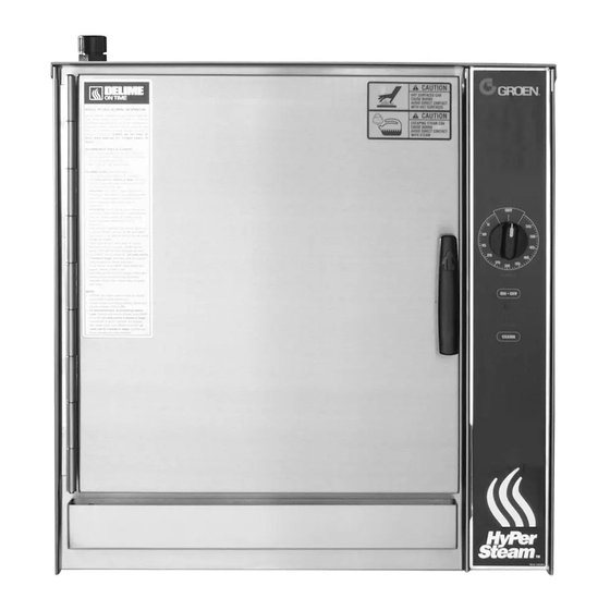
Equipment Description Your Groen HY-3E or HY-5E HyPerSteam Convection Steamer is designed to give years of service. It has a stainless steel cavity (cooking chamber) which is served by an independent atmospheric steam generator which is electrically heated. A powerful blower circulates the steam in the cavity to increase heating efficiency. -
Page 6: Water Conditioning
Water Conditioning It is essential to supply the steam generator with water that will not form scale or cause corrosion. Even though the steam generator is engineered to minimize scale formation and the effects of corrosion, their development depends on the quality of your water and the number of hours per day you operate the equipment. -
Page 7: Installation & Start-Up
Installation & Start-Up WARNING ELECTRICAL SUPPLY CONNECTION THE UNIT MUST BE INSTALLED BY PERSONNEL WHO ARE QUALIFIED TO Panel Removal WORK WITH ELECTRICITY AND PLUMBING. Open the wiring and control panel by removing the screws on the right side panel. IMPROPER INSTALLATION CAN CAUSE Slide the panel forward, and set it aside. - Page 8 Installation & Start-Up Equipotential Terminal In accordance with national regulations, each unit are fitted with an equipotential terminal. Branch Circuit Protection Each HY-3E Steamer should have its own branch circuit protection. Current and power demands for the different units are as shown in the table on page seven. WATER CONNECTION(S) The equipotential terminal is located Water pressure in the line should be between 30 and 60 PSIG (210 and 420 kPa) and...
-
Page 9: Installation & Start-Up
Installation & Start-Up FACTORY STACKED UNITS WARNING This section is applicable only if you are installing factory-stacked units. If you plan to DO NOT CONNECT THE UNIT DRAIN DIRECTLY stack steamers yourself, whether purchasing a new one for stacking or a kit to stack TO THE BUILDING DRAIN. -
Page 10: Operation
At this point you must turn off the power and contact an Authorized Groen Service Representative for repair. The HI TEMP indicator light comes on when the steam generator is too hot. -
Page 11: Operation
Operation OPERATING PROCEDURE WARNING Press the ON switch/pad for the steamer. The steam generator will fill, and heat WHEN YOU OPEN THE DOOR, STAY AWAY until the READY light comes on. (About 10 minutes.) FROM THE STEAM COMING OUT OF THE UNIT. -
Page 12: Cleaning
Stainless steel exterior cleaner such as Zepper® CLEAN ANY PART OF THE UNIT. Steam generator de-liming agent, such as Groen Delimer Descaler. A liquid de-liming agent will be easier to use than crystals or powders. See the warning DON’T MIX DE-LIMING AGENTS (ACID) WITH DE- about chlorides. -
Page 13: Cleaning
DELIME and POWER lights remain on (all lights will turn on, then off, except DELIME and POWER). STEP 4 After 5 minutes, beeper will beep rapidly, signaling you to add Groen Delimer/ Des- caler. Door(s) must remain closed for entire delime cycle. STEP 5 Pour 1 pint (2 cups) of delimer PER CAVITY into upper and /or lower deliming port(s) and then close port(s). -
Page 14: Maintenance
Troubleshooting This Groen Steamer is designed to operate smoothly and efficiently if properly maintained. However, the following is a list of checks to make in the event of a problem. Wiring diagrams are furnished inside the service panel. If an item on the check list is marked with (X), it means that the work should be done by a factory-authorized service representative. - Page 15 Parts List Model HY-3E (CE) Description Part # RIGHT SIDE PANEL 123134 LEFT SIDE PANEL 123135 DOOR ASSY, COMPLETE 094150 DOOR HANDLE 070123 DOOR GASKET 094147 LEFT PAN RACK 094148 BLOWER COVER/RACK 096788 DOOR LOCKING PIN 078914 DOOR PIN LOCK NUT 003823 CAVITY FAN 096790...
- Page 16 Parts List Model HY-3E (CE) Description Part # HEATER ELEM ASSY W/T- 128224 STAT 230V HEATER ELEM ASSY W/T- 128224 STAT 400V HEATER ELEM ASSY W/ OUT 123102 T-STAT 230V HEATER ELEM ASSY W/OUT 123102 T-STAT 400V HEATER ELEMENT GASKET 042366 HI LIMIT THERMOSTAT 122009...
- Page 17 101199 MOUNTING PLATE DRAIN VALVE* 071234 DRAIN VALVE BRACKET* 099991 DRAIN HOSE, STEAM GEN- 096806 ERATOR* CONDENSATE SPRAY HOSE* 096807 HARNESSES*-CALL GROEN AUTHORIZED SERVICE AGENT CAVITY* 096825 CAVITY INSULATION* 096738 WATER FLOW REDUCER* 112720 STEAM GENERATOR W/ 123199 INSULATION & PROBES*...
- Page 18 DIVERTER AND VENT ASSY 125918 DRAIN VALVE 071234 BRACKET, DRAIN VALVE 099991 EQUIPOTENTIAL TERMINAL 122021 ASSY DRAIN KIT 128237 WATER VALVE COVER PLATE 101199 DUAL SUPPLY GROEN DE-LIMER/DE- 114800 SCALER *Item not depicted/called out in drawing or photographs OM-HY/3E(CE) & HY/5E(CE)
- Page 19 Parts List Model HY-5E (CE) OM-HY/3E(CE) & HY/5E(CE)
- Page 20 Parts List Model HY-5E (CE) Description Part # Description Part # PLATFORM ASSEMBLY 125967 NUT, KEPS 10-32 071256 FAN MOTOR ASSEMBLY 096740 NUT, LOCK NYLON INSERT 119855 6-32 CHASSIS ASSEMBLY, ELEC- 119852 TRICA SCREW, RD HD SELF-TAP- 012398 PING 6-32 X 3/8 FUSE BLOCK ASSEMBLY 119848 SCREW SLOT HEX WASHER...
-
Page 21: Electrical Schematic
Electrical Schematic Model HY-3E (CE) OM-HY/3E(CE) & HY/5E(CE) - Page 22 Electrical Schematic Model HY-5E (CE) OM-HY/3E(CE) & HY/5E(CE)
-
Page 23: Service Procedures
Service Procedures [FOR PROFESSIONAL TECHNICAL SERVICE PERSONNEL ONLY] GENERAL INFORMATION WARNING The following procedures are based upon having access to the steamer on all four sides. THERE IS HIGH VOLTAGE INSIDE CONTROL If the steamer is installed between other appliances and there is not enough room on the COMPARTMENTS. - Page 24 Service Procedures [FOR PROFESSIONAL TECHNICAL SERVICE PERSONNEL ONLY] The following parts, devices and assemblies may be inspected, tested and/or replaced WARNING with only the removal of the right side cover panel: DISCONNECT THE POWER SUPPLY BEFORE BEGINNING ANY SERVICE PROCEDURE. Timer Assembly (P/N 100983 or 096826) Timer Fastener Nut (P/N 101145) •...
- Page 25 Service Procedures [FOR PROFESSIONAL TECHNICAL SERVICE PERSONNEL ONLY] • With a 7/16 inch nutdriver remove the two kep nuts. WARNING • Remove the steam port from the threaded studs. DISCONNECT THE POWER SUPPLY BEFORE BEGINNING ANY SERVICE PROCEDURE. To Install: •...
- Page 26 Service Procedures [FOR PROFESSIONAL TECHNICAL SERVICE PERSONNEL ONLY] Fan (P/N 096790) WARNING IMPORTANT: Make sure fan has come to a complete stop before working on it. DISCONNECT THE POWER SUPPLY BEFORE • To remove the fan from the cavity, open the door and remove the pan support BEGINNING ANY SERVICE PROCEDURE.
- Page 27 Service Procedures [FOR PROFESSIONAL TECHNICAL SERVICE PERSONNEL ONLY] • Using four hex/slotted 6-32 screws, screw the motor mounting plate to the WARNING motor with each screw passing through corresponding holes in the plate seal DISCONNECT THE POWER SUPPLY BEFORE holder. BEGINNING ANY SERVICE PROCEDURE.
- Page 28 Service Procedures [FOR PROFESSIONAL TECHNICAL SERVICE PERSONNEL ONLY] To Install: WARNING • Clamp thermostat bulb to the Number 2 Heater Rod. DISCONNECT THE POWER SUPPLY BEFORE • Apply pipe compound to the thread and tighten the compression fitting BEGINNING ANY SERVICE PROCEDURE. around the capillary in the threaded hole provided for this fitting.
- Page 29 Service Procedures [FOR PROFESSIONAL TECHNICAL SERVICE PERSONNEL ONLY] To Install: WARNING • Apply high temperature pipe compound to the probe and screw it in by hand. DISCONNECT THE POWER SUPPLY BEFORE Using a 13/16 inch open ended wrench, tighten the probe into the fitting. BEGINNING ANY SERVICE PROCEDURE.
- Page 30 Service Procedures [FOR PROFESSIONAL TECHNICAL SERVICE PERSONNEL ONLY] To Install: WARNING • Attach new drain valve to valve bracket. Pull silicone hose through drain valve DISCONNECT THE POWER SUPPLY BEFORE and install hose clamp over one end of the exposed hose and attach hose to BEGINNING ANY SERVICE PROCEDURE.
- Page 31 Service Procedures [FOR PROFESSIONAL TECHNICAL SERVICE PERSONNEL ONLY] 18. Door Removal/Installation/Alignment (P/N 094150) WARNING • To remove the door, turn off the steamer power and allow it to cool. Then, DISCONNECT THE POWER SUPPLY BEFORE remove door by supporting the weight of the door and remove hinge pin. BEGINNING ANY SERVICE PROCEDURE.
- Page 32 Service Procedures [FOR PROFESSIONAL TECHNICAL SERVICE PERSONNEL ONLY] • Remove the two screws from above and below the old bullet location and WARNING install them above and below the new bullet location. DISCONNECT THE POWER SUPPLY BEFORE • Remove screws and U-channel from the door. Take magnet and block BEGINNING ANY SERVICE PROCEDURE.
- Page 33 Service Procedures [FOR PROFESSIONAL TECHNICAL SERVICE PERSONNEL ONLY] • Apply a high temperature silicone sealant, such as RTV 159 or equivalent, to WARNING the four door spacers DISCONNECT THE POWER SUPPLY BEFORE • Install new gasket around outer door panel on insulation board. Be sure the BEGINNING ANY SERVICE PROCEDURE.
- Page 34 Service Procedures [FOR PROFESSIONAL TECHNICAL SERVICE PERSONNEL ONLY] To Install: WARNING • Apply a high temperature (922 degrees C) anti-seize, lubricating compound DISCONNECT THE POWER SUPPLY BEFORE on the bottom of the U-Channel surface that contacts with the spring. BEGINNING ANY SERVICE PROCEDURE. •...
-
Page 35: Service Log
Service Log Model No: Purchased From: Serial No: Location: Date Purchased: Date Installed: Purchase Order No: For Service Call: Date Maintenance Performed Performed By OM-HY/3E(CE) & HY/5E(CE) - Page 36 1055 Mendell Davis Drive • Jackson MS 39272 888-994-7636 • 601-372-3903 • Fax 888-864-7636 unifiedbrands.net PART NUMBER 128174, REV G (07/14) © 2014 Unified Brands. All Rights Reserved. Unified Brands is a wholly-owned subsidiary of Dover Corporation.
Need help?
Do you have a question about the HYPERSTEAM HY-3E and is the answer not in the manual?
Questions and answers