Table of Contents
Advertisement
OPERATOR MANUAL &
SERVICE MANUAL
IMPORTANT INFORMATION, KEEP FOR OPERATOR
This manual provides information for:
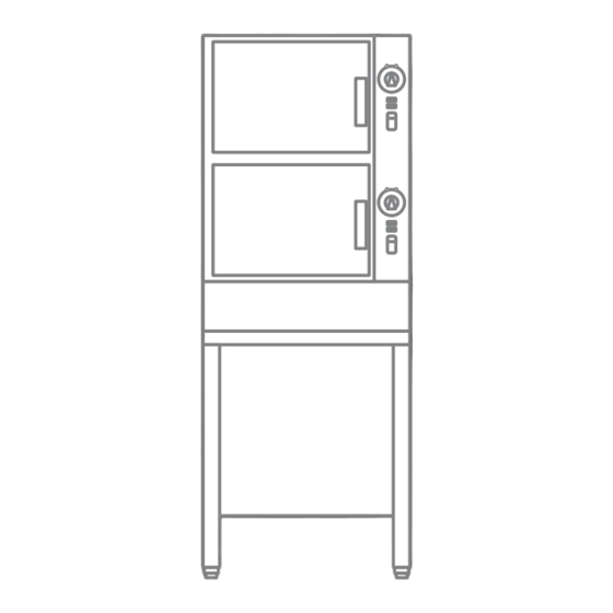
HY-6G(CE) HYPERSTEAM
ATMOSPHERIC CONVECTION
STEAMER
· Self-Contained
· Gas Heated
· Capacity: 6 Steamer Pans (305 x 508 x 64mm)
THIS MANUAL MUST BE RETAINED FOR FUTURE REFERENCE.
READ, UNDERSTAND AND FOLLOW THE INSTRUCTIONS AND
WARNINGS CONTAINED IN THIS MANUAL.
NOTIFY CARRIER OF DAMAGE AT ONCE
It is the responsibility of the consignee to inspect the container upon receipt of
same and to determine the possibility of any damage, including concealed dam-
age. Unified Brands suggests that if you are suspicious of damage to make a
notation on the delivery receipt. It will be the responsibility of the consignee to file
a claim with the carrier. We recommend that you do so at once.
Manufacture Service/Questions 888-994-7636.
Information contained in this document is known to be current and accurate at the time
of printing/creation. Unified Brands recommends referencing our product line websites,
unifiedbrands.net, for the most updated product information and specifications.
PART NUMBER 128805, REV. C (4/06)
INTERNATIONAL
™
1055 Mendell Davis Drive
888-994-7636, fax 888-864-7636
Jackson, MS 39272
groen.com
Advertisement
Table of Contents

Related Manuals for Groen GROEN HYPERSTEAM HY-6G(CE


Summary of Contents for Groen GROEN HYPERSTEAM HY-6G(CE
- Page 1 Unified Brands suggests that if you are suspicious of damage to make a notation on the delivery receipt. It will be the responsibility of the consignee to file a claim with the carrier.
- Page 2 OM/SM-HY-6G(CE) IMPORTANT — READ FIRST — IMPORTANT IT IS MOST IMPORTANT THAT THESE INSTRUCTIONS AND THE OPERATOR AND SERVICE MANUALS BE CONSULTED BEFORE INSTALLING AND COMMISSIONING THE APPLIANCE. FAILURE TO COMPLY WITH SPECIFIED PROCEDURES MAY RESULT IN DAMAGE OR THE NEED FOR A SERVICE CALL. THESE APPLIANCES HAVE BEEN CE MARKED ON THE BASIS OF COMPLIANCE WITH THE GAS APPLIANCE DIRECTIVE, EMC AND LOW VOLTAGE DIRECTIVE FOR THE COUNTRIES, GAS TYPES AND PRESSURES AS STATED ON THE DATA PLATE.
-
Page 3: Table Of Contents
OM/SM-HY-6G(CE) Table of Contents EQUIPMENT DESCRIPTION ..........4 INSPECTION AND UNPACKING . -
Page 4: Equipment Description
OM/SM-HY-6G(CE) 1.0 - Equipment Description Your Groen HY-6G (CE) HyPerSteam Convection Steamer is designed to give years of service. It has two stainless steel cavities (cooking chambers) which are served by twin, independent atmospheric steam generators which are gas-heated. A powerful blower circulates the steam in each cavity to increase heating efficiency. -
Page 5: Water Conditioning/Requirements
OM/SM-HY-6G(CE) 3.0 - Water Conditioning It is essential to supply the steam generator with 3.2 If your water contains scale-forming minerals, as water that will not form scale. Even though the steam most water does, use a well-maintained water generator is engineered to minimize scale formation, softener. -
Page 6: Installation, Start-Up And Conversion Instructions
OM/SM-HY-6G(CE) 4.0 - Installation, Start-Up and Conversion WARNING THE UNIT MUST BE INSTALLED BY PERSONNEL WHO ARE QUALIFIED TO WORK WITH ELECTRICITY AND PLUMBING. IMPROPER INSTALLATION CAN CAUSE INJURY TO PERSONNEL AND/OR DAMAGE TO THE EQUIPMENT. THE UNIT MUST BE INSTALLED IN ACCORDANCE WITH APPLICABLE CODES. CAUTION DO NOT INSTALL THE UNIT WITH THE RIGHT SIDE VENTS BLOCKED OR WITHIN 30 CENTIMETERS OF A HEAT SOURCE (SUCH AS A BRAISING PAN, DEEP FRYER, CHAR BROILER, OR KETTLE). - Page 7 OM/SM-HY-6G(CE) 4.3.2 Injector Diameters GAS INPUT RATE BTU/HR AND KW Natural Gas Propane Gas Natural Gas Propane Gas HY-6G(CE) 9.25 mBar 26.25 mBar Injector No. of Injector No. of (3.7 in. W.C) (10.5 in. W.C.) Dia. (mm) Injectors Dia. (mm) Injectors Main Individual...
- Page 8 OM/SM-HY-6G(CE) Install a WRAS approved double-check valve or an 4.6 Initial Start-Up equally effective backflow preventive device in the After the HY-6G(CE) Steamer has been installed, incoming cold water line at the point of connnection(s) test it to ensure that the unit is operating correctly. to the steamer and in compliance with all local plumbing codes.
- Page 9 OM/SM-HY-6G(CE) a. Set the timer to the desired time for timed Then the unit will come back on and resume steaming. operation in the mode and with the (running) timer value existing just prior to shutdown. The pilot b. Turn the timer knob to the manual ON switch may be turned off during “off hours”...
-
Page 10: Operation
OM/SM-HY-6G(CE) 5.0 - Operation WARNING ANY POTENTIAL USER OF THE EQUIPMENT SHOULD BE TRAINED IN SAFE AND CORRECT OPERATING PROCEDURES. 5.1 Controls Gas Lockout Indicator and Reset Control Operator controls are on the front right of the unit. Should the pilot fail to ignite during start-up, a yellow The control panel has the following touch pads and indicator on the control panel (see page 11) will light indicator lights. - Page 11 OM/SM-HY-6G(CE) Upper Portion of HY-6G(CE) Control Panel OM/SM-HY-6G(CE)
-
Page 12: Cleaning
OM/SM-HY-6G(CE) 6.0 - Cleaning To keep your HY-6E Steamer in proper working condition/order, use the following procedure to clean the unit. This regular cleaning will reduce the effort required to clean the steam generators and cavities. 6.1 Suggested Tools WARNING 1. - Page 13 OM/SM-HY-6G(CE) 7. Replace fan baffle partition and close door. 6.2.2 Steam Generator and Cooking Chamber 8. The cleaning cycle consists of a boiling clean The steamer cavity and steam generator may be cleaned separately. When cleaning is scheduled, or stage, a soak stage, and a rinse stage. The full if the SERVICE light is on, follow these simple de- cycle takes about 50 minutes to complete.
-
Page 14: Maintenance
OM/SM-HY-6G(CE) 7.0 - Maintenance The HY-6G(CE) Steamer is designed for minimum 2. Inspect the cooking chamber drain to be sure maintenance, and no user adjustments should be it is not blocked. necessary. Certain parts may need replacement after 3. Adjust the latch pin to allow for changes that prolonged use. -
Page 15: Parts List
OM/SM-HY-6G(CE) 9.0 - Parts List 9.1 External Cabinet and Sheet Metal Description Part No. Description Part No. Lower Side Panels 096848 Upper Right Side Panel 123183 Lower Front Panel 096720 Lower Back Panel 096785 Adjustable Table Leg 042505 Sink Drain Fitting 099943 Door 094150... - Page 16 OM/SM-HY-6G(CE) 9.0 - Parts List 9.2 Cavity Control Section Description Part No. Description Part No. Top Cover Clip 123156 Fan Motor 096740 Timer 100983 Motor Capacitor, 3 MFD 096813 Door Switch 096857 Cover, Control Panel 128800 Ready Thermostat 088865 Steamer Control PC Board 119801 Steam Port 088874...
- Page 17 OM/SM-HY-6G(CE) 9.0 - Parts List 9.3 Steamer Base Section - Front Description Part No. Description Part No. Terminal Block 003887 Gas Pilot Switch, Rocker 087951 Cover, Housing 128766 Reset Switch, Pushbutton 122003 Relay, 12V DC 119813 Circuit Breaker, 10 Amp 119860 Water Level Probes 070178...
- Page 18 OM/SM-HY-6G(CE) 9.0 - Parts List 9.4 Steamer Base - Rear Description Part No. Description Part No. Gas Valve, 24V 122120 1/4" Tubing, Pilot 122140 1/2" Tubing 123707 Manifold Fitting Assembly 123705 3/8" Tubing 096712 Manifold Fitting Assembly 123704 Heat Shield 123711 Regulator 100513...
- Page 19 OM/SM-HY-6G(CE) 9.0 - Parts List 9.5 Steamer Plumbing Description Part No. Description Part No. Plate, Cover, Water Inlet 098693 Gen Drain Hose Clamps 095656 Hose, PVC, Clear 099915 Drain Box 096791 Hose, Condensate 096771 Drain Box Flap 099213 Drain Kit 127393 Drain Box Cover 096792...
- Page 20 OM/SM-HY-6G(CE) 9.0 - Parts List 9.6 Steamer Motor and Controls Description Part No. Description Part No. Fan Motor 096740 Timer Knob 123100 Timer Fastener Nut 101145 Door Switch 096857 Motor Shaft Seal 096868 Steam Port Kit* 118102 Motor Insulator 094135 -Ready Thermostat 088865 096790...
- Page 21 OM/SM-HY-6G(CE) 9.0 - Parts List 9.7 Steamer Generator Individual Parts Description Description Steam Gen Weldment, Inner 094128 Bottom Cavity Drain Hose 088846 Steam Gen Weldment, Outer 123655 Top Steam Hose 099953 Right Steam Gen. Insulation 096896 Sink Drain Hose 099915 Left Steam Gen.
- Page 22 OM/SM-HY-6G(CE) 9.0 - Parts List 9.7 Steamer Individual Parts Description Part No. Description Part No. Main Gas Valve 122158 Pilot Gas Switch 087951 Regulator - Natural Gas 100513 Water Inlet Valve - 3 outlet 090827 Gas Manifold(Left) 123705 Steam Generator Drain Valve 071234 Gas Manifold (Right) 123704...
-
Page 23: Service Procedures
OM/SM-HY-6G(CE) 10.0 - Service Procedures The following procedures are based upon having access to the steamer on all four sides. If the steamer is installed between other appliances and there is not enough room on the sides for access, the steamer must then be pulled out from its position to gain proper access. - Page 24 OM/SM-HY-6G(CE) 6. Position the valve over the valve mounting threaded the two screws. Make sure that the valve is NOT studs and connect both ends of the hose to the drain installed upside down. box and steam generator. 9. Re-attach the hoses to the valve. Slide the hoses all 7.
- Page 25 OM/SM-HY-6G(CE) 6. Replace cover on drain box and lower vent pipe into 18. Once the steam generator has been removed, the the drain box. fittings and probes may be transferred to the new steam generator. Make sure that all screw fittings are 10.9 Steam Generator installed using high temperature pipe compound.
- Page 26 OM/SM-HY-6G(CE) main gas valve assembly using an open-ended 4. From the left side (or back) of the steamer, use a wrench. Be careful not to move the aluminum tubing wrench to loosen and disconnect the aluminum excessively, or to bend it. tubing to the inner and outer manifolds.
- Page 27 OM/SM-HY-6G(CE) terminals from the igniter module. Be careful not to 7. Remove the flame sensor from the flame sensor pull the terminal by the wire. Use needle nose pliers bracket. to grip onto the terminal itself. 8. Remove the pilot burner. 5.
- Page 28 OM/SM-HY-6G(CE) 12. Fit the burner manifold to the steam generator WARNING manifold mounting bracket. DO NOT ATTEMPT TO LIGHT THE PILOT BURNER WITH A FLAME. 13. Reinstall and tighten the aluminum tubes to the burner manifold. 4. Ignite the pilot. The micrometer should read 3 microamps minimum.
- Page 29 OM/SM-HY-6G(CE) 10.18 P/N 096790 7. To prepare motor for mounting, slide the oil slinger washer onto the shaft about ½" (12 mm) down the shaft. IMPORTANT: Make sure that the fan has come to a complete stop before attempting any work on the fan. IMPORTANT: This washer has two surfaces: A 1.
- Page 30 OM/SM-HY-6G(CE) 1. Turn off power to the steamer. cavity and one for the bottom cavity. If both hoses are to be replaced, replace them one at a time. 2. Unplug the two wires from the thermostat. 1. Shut off power to the steamer. 3.
- Page 31 OM/SM-HY-6G(CE) 5. Loosen lock nut with a wrench. Remove door locking To Align: pin and lock nut. 5. Place a piece of masking tape over the door pin (bullet) hole in the door. 6. Coat bullet threads with NEVER-SEEZ high temperature compound.
- Page 32 OM/SM-HY-6G(CE) 18. The wires for the alternate door switch may be 13. Align door to steamer, per Paragraph 10.24.. foundunder the cavities. Connect the two wires from the switch to the wiring harness. 10.28 Door Handle, Magnet and Block Assembly Door Handle P/N 070123 19.
- Page 33 OM/SM-HY-6G(CE) 6. Install spring onto brass roller, then place square 2. Note and record the distance between the lock nut plate over spring. and the end of the (bullet shaped) door locking pin. This information is important and will be needed for 7.
- Page 34 OM/SM-HY-6G(CE)
-
Page 35: Schematic
12.0 - Service Log Model No. Purchased From Serial No. Location Date Purchased Date Installed Purchase Order No. For Service Call Date Maintenance Performed Performed by OM/SM-HY-6G(CE) - Page 36 Limited Warranty To Commercial Purchasers* (for Areas Outside of the U.S. and Canada) Groen Foodservice Equipment ("Groen Equipment") has been skillfully manufactured, carefully inspected and packaged to meet rigid standards of excellence. Groen warrants its Equipment to be free from defects in material and workmanship for twelve months from date of installation or eighteen months from date of shipment with the following conditions and subject to the following limitations.
-
Page 37: Warranty Protection
1055 Mendell Davis Drive • Jackson MS 39272 888-994-7636 • 601-372-3903 • Fax 888-864-7636 groen.com PART NUMBER 128805, REV. C (4/06)
Need help?
Do you have a question about the GROEN HYPERSTEAM HY-6G(CE and is the answer not in the manual?
Questions and answers