Table of Contents
Advertisement
Quick Links
Download this manual
See also:
Manual
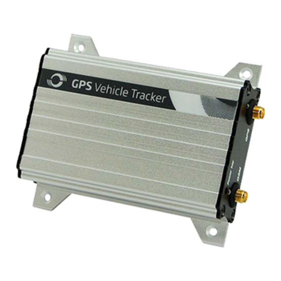
MEITRACK® GPS Vehicle Tracker
Copyright © 2014 Meitrack Group All rights reserved.
File Name:
MEITRACK MVT340 User Guide
Project:
MVT340
Sub Project:
User Guide
Revision:
V2.9
User Guide
MVT340
Creator:
Cavana Cheung
Creation Date:
Update Date:
Page:
Confidential:
External Documentation
2010-08-26
2013-09-13
- 1 - of 18
- 1 -
Advertisement
Table of Contents

Related Manuals for MeiTrack MVT340


Summary of Contents for MeiTrack MVT340
-
Page 1: User Guide
MVT340 Creation Date: 2010-08-26 Update Date: 2013-09-13 Sub Project: User Guide Page: - 1 - of 18 Revision: V2.9 Confidential: External Documentation MEITRACK® GPS Vehicle Tracker User Guide MVT340 Copyright © 2014 Meitrack Group All rights reserved. - 1 -... -
Page 2: Table Of Contents
7.1.4 Output (PIN8) ..........................- 17 - 7.1.5 Analog Input (PIN7) ........................- 17 - 7.2 Install GPS/GSM Antenna ........................- 18 - 7.3 Mount the MVT340 unit ........................- 18 - Copyright © 2014 Meitrack Group All rights reserved. - 2 -... -
Page 3: Copyright And Disclaimer
Meiligao (MEITRACK), or transmitted in any form, either electronically or mechanically, including photocopying and recording. In no event shall Meiligao (MEITRACK) be liable for direct, indirect, special, incidental, or consequential damages (including but not limited to economic loss, personal injury, and loss of asset and property) arising out of the use or inability or illegality to use the product or documentation. -
Page 4: Specifications
2 Digital Input (1 negative triggering and 1 positive triggering) 1 Analog Input Detection 1 Output 1 USB port for configuration only 4. MVT340 and Accessories MVT340 with I/O Cable + USB Data Cable Battery Button Antenna Antenna Copyright © 2014 Meitrack Group All rights reserved. - 4 -... -
Page 5: View
3 hours. 8 hours is highly appreciated. Configuration and testing suggested prior to installation. 6.3 LED Indicators Press and hold down the Power button for 3~5 seconds, and then the MVT340 will automatically start. Copyright © 2014 Meitrack Group All rights reserved. - 5 -... -
Page 6: Track By Calling
MVT340 is connected to the GSM network Flashing (1 second on and 2 seconds off) MVT340 is not connected to the GSM network 6.4 Track by Calling Make a call to MVT340 and it will report with one SMS. For example, Now,110727 02:48,V,16,23Km/h,61%,http://maps.google.com/maps?f=q&hl=en&q=22.540103,114.082329 &ie=UTF8&z=16&iwloc=addr&om=1 Click on the link then the location can be shown directly on Google Maps on your mobile phone. -
Page 7: Multiple Phone Numbers- A71
Password is 4 digits only and defaulted as 0000. You can change the password by Parameter Editor and SMS command. MVT340 will only accept commands from a user with the correct password and report SMS report to the user. If preauthorized phone number was set, only this phone number can receive SMS reports. -
Page 8: Sleep Mode - A73
If no preset phone number, it is empty (default is empty). Send command “0000, A71” to delete all phone numbers. When the SOS button is pressed, MVT340 will make a call to phone number 1, 2 and 3. It will stop calling when one number answers. -
Page 9: Set Anti-Theft- B21
This part mainly shows you how to use the MEITRACK Parameter Editor. Note: Don’t connect MVT340 to external battery when configuring. Please refer to the MEITRACK Parameter Editor User Guide for more information regarding configuration and functions. Run ‘PL2303_Prolific_DriverInstaller’ to install the driver for the USB data cable. - Page 10 ‘Prolific USB-to-Serial Comm Port’ as the following picture shows. Note: Remember this Com number. It needs to be input into the MEITRACK Parameter Editor. It is COM3 in this example and it would be COM4 or COM5… in your computer.
-
Page 11: Sms Tracking
Click ‘Read Settings’ button to show the default or previous settings of the tracker. Note: MEITRACK Parameter Editor is in the CD. The language will be automatically adjusted to be the same as your PC operation system’s language. Please use “Ctrl+L” to change the language. - Page 12 Event Selected event’s SMS reports will be sent to the authorized phone number. For more details, please refer to MEITRACK GPRS/SMS Protocol. For description of events from SOS/Input 1 Active to Tow Alarm, please refer to tap II GPRS Tracking.
-
Page 13: Gprs Tracking
External Power Off Alarm when external power supply if off or cut. No GPS Signal Report when MVT340 enters GPS blind area or no GPS signal. Get GPS Signal Report when MVT340 exits GPS blind area or get GPS signal. - Page 14 Interval = 0, stop tracking by time interval. Max time interval = 65535*10 seconds GPRS Report Times = 0, report without limit. = [1,65535], set report times, MVT340 will stop reporting when reaching the times. IP & Port Input server’s IP address and port number.
- Page 15 External Power Off Alarm when external power supply if off or cut. No GPS Signal Report when MVT340 enters GPS blind area or no GPS signal. Get GPS Signal Report when MVT340 exits GPS blind area or get GPS signal.
-
Page 16: Installation
Output open drain sink voltage (ineffective): 45V max. Output low voltage sink current (effective): 500mA max. 7.1.1 POWER/GND (PIN1, PIN2) Connect GND (-Black) and Power (+Red) wires to the battery of vehicle. Copyright © 2014 Meitrack Group All rights reserved. - 16 -... -
Page 17: Digital Input (Pin3, Negative Triggering)
7.1.3 Digital Input (PIN5, Positive Triggering) 7.1.4 Output Control (PIN8) 7.1.5 Analog Input (PIN7) 7.1.5.1 Analog Input Application 1– Detect External Power Voltage Input range: 0-6V Voltage Caculating Formula: input voltage=(AD*6)/1024 0x0377=>887(Decimal)=>(887*6)/1024=5.1972V(Voltage) 0x02FB=>763(Decimal)=>(763*6)/1024=4.4707V(Voltage) Copyright © 2014 Meitrack Group All rights reserved. - 17 -... -
Page 18: Install Gps/Gsm Antenna
Note: Do not shield or cover the GPS antenna with any objects containing metal. 7.3 Mount the MVT340 unit If mounting required, there are 4 screw holes on the MVT340, 2 along either side that act as fixing points to the vehicle.
Need help?
Do you have a question about the MVT340 and is the answer not in the manual?
Questions and answers