Table of Contents
Advertisement
Quick Links
See also:
Manual
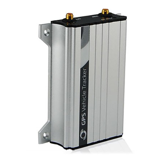
MEITRACK® GPS Vehicle Tracker
Copyright © 2014 Meitrack Group All rights reserved.
File Name:
MEITRACK MVT380 User Guide
Project:
MVT380
Sub Project:
User Guide
Revision:
V2.8
User Guide
MVT380
Creator:
Cavana Cheung
Creation Date:
Update Date:
Page:
Confidential:
External Documentation
2010-08-26
2013-09-13
- 1 - of 22
- 1 -
Advertisement
Table of Contents

Related Manuals for MeiTrack MVT380


Summary of Contents for MeiTrack MVT380
-
Page 1: User Guide
MVT380 Creation Date: 2010-08-26 Update Date: 2013-09-13 Sub Project: User Guide Page: - 1 - of 22 Revision: V2.8 Confidential: External Documentation MEITRACK® GPS Vehicle Tracker User Guide MVT380 Copyright © 2014 Meitrack Group All rights reserved. - 1 -... -
Page 2: Table Of Contents
7.1.5 Analog Input (PIN6/PIN14) ............. - 20 - 7.2 Install GPS/GSM Antenna ................ - 21 - 7.3 Install Microphone and Speaker (Optional) ..........- 21 - 7.4 Mount the MVT380 unit ................- 21 - Copyright © 2014 Meitrack Group All rights reserved. - 2 -... -
Page 3: Copyright And Disclaimer
Meiligao (MEITRACK), or transmitted in any form, either electronically or mechanically, including photocopying and recording. In no event shall Meiligao (MEITRACK) be liable for direct, indirect, special, incidental, or consequential damages (including but not limited to economic loss, personal injury, and loss of asset and property) arising out of the use or inability or illegality to use the product or documentation. -
Page 4: Specifications
Positioning 10 meters Accuracy 5 Digital input ( 2 positive triggering and 3 negative triggering) 2 Analog input detection 5 Output 1 USB port 1 earphone and microphone jack Copyright © 2014 Meitrack Group All rights reserved. - 4 -... -
Page 5: Mvt380 And Accessories
Check that the SIM Lock code is turned off; If you require the function of sending an SMS location report to the authorized phone number when it makes a call to the MVT380, please make sure the SIM installed supports displaying caller ID. -
Page 6: Charging
3 hours. 8 hours is highly appreciated. Configuration and testing suggested prior to installation. 6.3 LED Indications Press and hold the Power On/Off button for 3~5 seconds to turn on/off MVT380. GPS LED (Blue) One button is pressed or input is active. - Page 7 If your mobile cannot visit HTTP websites, input the latitude and longitude into Google Maps as the following picture shows to get the position: More SMS commands You can configure MVT380 by mobile phone or by computer using the MEITRACK Parameter Editor. For more details, please refer to part 6.5 Configure by Computer. Note: Password is 4 digits only and defaulted as 0000.
-
Page 8: Multiple Phone Numbers- A71
If no preset phone number, it is empty (default is empty). Send the “0000, A71” command to delete all phone numbers. When the SOS button is pressed, MVT380 will make a call to phone number 1, 2 and 3. It will stop calling when one number answers. -
Page 9: Geo-Fence Alarm - B05
Status=1, turn on Anti-theft (default); the device alarms when input 2 (negative input) and input 4 (positive input) are active; Status=0, turn off Anti-theft; the device doesn’t alarm when input 2 (negative input) and input 4 (positive input) are active. 6.4.6 Time Zone– B35 Command: 0000,B35,T Copyright © 2014 Meitrack Group All rights reserved. - 9 -... -
Page 10: Configure By Computer
This part shows the basics of how to use the MEITRACK Parameter Editor. Note: Don’t connect MVT380 to external battery when configuring. Please refer to the MEITRACK Parameter Editor User Guide for more detailed information regarding configuration and functions. Run ‘PL2303_Prolific_DriverInstaller’ to install the driver for the USB data cable. -
Page 11: Sms Tracking
Confidential: External Documentation Note: Remember this Com number. It needs to be input into the MEITRACK Parameter Editor. It is COM3 in this example and it would be COM4 or COM5… in your computer. Run ‘MEITRACK Parameter Editor.exe’ and the following configuration window will pop up: Choose the correct Com number and device model No. - Page 12 = [1,255], it will stop reporting when reaching preset times Read Read tracker’s current settings for above items. Write Write above settings to the tracker. 6.5.1.2 SMS Report Tap V: Click Authorization Copyright © 2014 Meitrack Group All rights reserved. - 12 -...
- Page 13 A phone number to receive selected event’s SMS reports. Event Selected event’s SMS reports will be sent to authorize phone number. For more details, please refer to MEITRACK GPRS/SMS Protocol. For description of events from SOS/Input 1 Active to Tow Alarm, please refer to tap II GPRS Tracking.
- Page 14 External Power Off Alarm when external power supply if off or cut. No GPS Signal Report when MVT380 enters GPS blind area or no GPS signal. Get GPS Signal Report when MVT380 exits GPS blind area or get GPS signal.
-
Page 15: Gprs Tracking
Max time interval = 65535*10 seconds GPRS Report Times = 0, report without limit. = [1,65535], set report times, MVT380 will stop reporting when it has sent the report this many times. IP & Port Input server’s IP address and port number. - Page 16 External Power Off Alarm when external power supply if off or cut. No GPS Signal Report when MVT380 enters GPS blind area or no GPS signal. Get GPS Signal Report when MVT380 exits GPS blind area or get GPS signal.
-
Page 17: Installation
Tow Alarm Alarm when the tracker trembles for a period of time. You can define tow time on tap III Main Settings. For more information about GPRS settings, please refer to MEITRACK SMS/GPRS Protocol. 6 Installation 7.1 Install I/O Cable The I/O cable is a 16-pin cable including power, analog input, negative/positive input and output. - Page 18 16 (POWER) Positive pole of the power output. The output voltage is equal to that of the PIN 8. It is used for supply power to an external device. Copyright © 2014 Meitrack Group All rights reserved. - 18 -...
-
Page 19: Power/Gnd (Pin7/Pin8)
External Documentation 7.1.1 Power/GND (PIN7/PIN8) Connect GND (-Black) and Power (+Red) wires to the battery of vehicle. 7.1.2 Digital Input (PIN1/PIN2/PIN3 Negative Triggering) 7.1.3 Digital Input (PIN4/PIN5 Positive Triggering) Copyright © 2014 Meitrack Group All rights reserved. - 19 -... -
Page 20: Output (Pin9/Pin10/Pin11/Pin12/Pin13)
7.1.5.2 Analog Input Application 2 – Fuel Level Detection (percentage of fuel) Note: Fuel level sensors supplied by Meitrack are A53 resistance voltage output sensors. The sensors need to be Copyright © 2014 Meitrack Group All rights reserved. - 20 -... -
Page 21: Install Gps/Gsm Antenna
7.3 Install Microphone and Speaker (Optional) 7.4 Mount the MVT380 unit If mounting required, there are 4 screw holes on the MVT380, 2 along either side that act as fixing points to the Copyright © 2014 Meitrack Group All rights reserved. - Page 22 Sub Project: User Guide Page: - 22 - of 22 Revision: V2.8 Confidential: External Documentation vehicle. Please do not hesitate to email us at info@meitrack.com if you have any questions. Copyright © 2014 Meitrack Group All rights reserved. - 22 -...
Need help?
Do you have a question about the MVT380 and is the answer not in the manual?
Questions and answers