Table of Contents
Advertisement
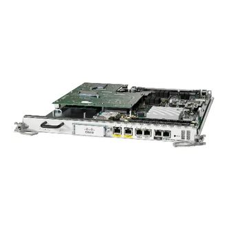
Performance Route Processor
Installation and Configuration
Product Number: PRP-2=, PRP-3=
Document Order Number: OL-17436-01
This hardware installation and configuration note describes the performance route processor (PRP)
PRP-2 and PRP-3 route processors for use in Cisco XR 12000 Series Routers and Cisco 12000 Series
Routers.
Document Contents
This publication includes the following sections:
•
•
•
•
•
•
•
•
•
•
Americas Headquarters:
Cisco Systems, Inc., 170 West Tasman Drive, San Jose, CA 95134-1706 USA
Important Information, page 2
Product Overview, page 3
Preparing for Installation, page 17
Removing and Installing a PRP, page 19
Checking the Installation, page 23
Upgrading to the PRP, page 31
Configuring Interfaces on the PRP, page 41
Configuring Interfaces on the PRP-3, page 48
Additional Configuration and Maintenance Tasks, page 59
Regulatory, Compliance, and Safety Information, page 84
Advertisement
Chapters
Table of Contents

Related Manuals for Cisco PRP-2


Summary of Contents for Cisco PRP-2
-
Page 1: Table Of Contents
Product Number: PRP-2=, PRP-3= Document Order Number: OL-17436-01 This hardware installation and configuration note describes the performance route processor (PRP) PRP-2 and PRP-3 route processors for use in Cisco XR 12000 Series Routers and Cisco 12000 Series Routers. Document Contents... -
Page 2: Important Information
PRP Redundancy When two PRPs are installed in a Cisco XR 12000 Series Router, one PRP is the active PRP and the other is a backup, or standby, PRP. If the active PRP fails or is removed from the system, the standby PRP detects the failure and initiates a switchover. -
Page 3: Product Overview
ETH 2 PERFORMANCE ROUTE PROCESSOR 2 The PRP-2 is available as product number PRP-2 or PRP-2=, which includes one PRP with 1 G of synchronous dynamic random-access memory (SDRAM) and one 64-MB advanced technology attachment (ATA) Flash disk. A redundant PRP (product number PRP-2/R) is also available. - Page 4 Cisco IOS XR image without the support of bootflash memory. Note PRP-3 supports Cisco XR 124xx (10 G per slot fabric) and Cisco XR 128xx (40 G per slot fabric) Router chassis only. PRP-3 does not support Cisco XR 120xx Router chassis (2.5-G low-speed fabric).
- Page 5 Sensors—Air-temperature sensors for environmental monitoring. • Note For Cisco IOS XR Release 3.7.0 and later releases, SDRAM and Compact Flash memories require 2 GB capacity. Differences Between PRP-2 and PRP-3 Table 2 provides details about hardware or software component differences between PRP-2 and PRP-3.
- Page 6 XR 128xx Series Router chassis Series Router chassis Cisco IOS Software Storage The Cisco IOS Software images are stored in flash memory. Two types of flash memory ship with the PRP-1: Onboard flash memory—Ships as a single in-line memory module (SIMM). This flash memory •...
- Page 7 RAM, sets up some initial hardware needed, and then hands over control to the CPU. The CPU thereafter takes on and loads the Cisco IOS XR software to enable the router to come up. The ROMMON in PRP-3 is now more intelligent than the ROMMON in PRP-1 or PRP-2. The ROMMON of PRP-1 and PRP-2 needed a boothelper image to reach TFTP and download the Cisco IOS XR software image.
- Page 8 Data successfully written to NVRAM Step 4 To enable loading of the Cisco IOS XR software image from TFTP server, add the IP address, subnet mask, and gateway address of the TFTP from which the request is finally sent. Note Upon adding the route details of the TFTP server and gateway, a route table is created on ROMMON.
- Page 9 Load the Cisco IOS XR software image from the TFTP server by specifying the TFTP server IP address, Step 10 the location of the image, and the filename of the Cisco IOS XR software image. The IOS XR software image is loaded, and later all the packages and additional software upgrades are stored in the specified boot device.
- Page 10 ROMMON. This has to be done in the early stage of booting. PRP Hardware Components Figure 3 shows the locations of the various hardware components on the PRP-2. Memory options and functions for both are listed in Table...
- Page 11 — 1. Default SDRAM configuration is 2-GB for PRP-2. Bank 1 (U15) must be populated first. You can use one or both banks to configure SDRAM combinations of 2 GB and 4 GB for the PRP-2. 1.5-GB configurations.and DIMM devices that are not from Cisco are not supported.
- Page 12 Product Overview Figure 4 PRP-3 (Horizontal Orientation) SDRAM DIMM: Bank 1 - Socket number U8 SDRAM DIMM: Bank 2 - Socket number U10 External Compact Flash Hard Disk (80 GB) Internal Compact Flash OL-17436-01...
- Page 13 The default PRP-2 configuration includes 1 GB of ECC SDRAM. DIMM upgrades of 1 GB and 2 GB are available for the PRP-2. You can mix memory sizes as long as the larger DIMM is placed in bank 1 (U15).
-
Page 14: Flash Memory
Flash memory also functions as a Trivial File Transfer Protocol (TFTP) server to allow other servers to boot remotely from stored images or to copy them into their own Flash memory. The onboard Flash memory (called bootflash) contains the Cisco IOS boot image, and the Flash disk contains the Cisco IOS software image. - Page 15 The boot process and the content displayed are controlled by the MBus module software of the PRP. At the end of the boot process, the LEDs are controlled by the Cisco IOS software (via the MBus), and the content displayed is designated by the Cisco IOS software.
- Page 16 The PRP includes two Flash disk slots on the front panel of the card. Either slot on the PRP-1 can support an ATA Flash disk or a linear Flash memory card. The Flash disk slots on the PRP-2 can only support ATA Flash disks.
-
Page 17: Preparing For Installation
Note Hard Disk Drive The PRP-2 optionally includes a 40-GB hard disk drive (HDD) that is installed on the PRP-2 board. The PRP-3 provides an 80-GB hard disk drive (HDD) that is installed on the PRP-3 board. Hard disk drives that are not from Cisco are not supported. -
Page 18: Safety Guidelines
Do not wear loose clothing, jewelry, or other items that could get caught in the router while working • with line cards. Cisco equipment operates safely when it is used in accordance with its specifications and product • usage instructions. -
Page 19: Removing And Installing A Prp
The procedures in the following sections use illustrations of a Cisco 12404 Internet Router to support Note the descriptions of installing and removing a route processor card. The card cages of Cisco XR 12000 Series Routers differ in many ways. However, the process of installing and removing a route processor card are basically the same across the entire chassis line. - Page 20 Removing and Installing a PRP You must remove the PRP-2 before you can install or remove the compact flash disk or the hard disk Note drive. See the “Additional Configuration and Maintenance Tasks” section on page 59 for more information.
- Page 21 CO NS OL IDA TE D SW ITC H FA BR Figure 7 shows the ejector levers in detail. Figure 7 Ejector Lever Detail (Cisco 12404 shown) CLEA N CLASS 1 LASER PRODU CT CONNEC LASERP RODUK WITH ALCOHOL T DER KLASSE...
- Page 22 Removing and Installing a PRP If you are replacing a PRP, disconnect any devices that are attached to the Ethernet, console, or auxiliary Step 4 ports. If you are removing a PRP for maintenance and will reinstall the same one, you can leave the devices attached, provided that doing so will not strain the cables.
-
Page 23: Checking The Installation
) to boot the Cisco IOS software. Rommon> When the Cisco IOS software boots, it polls all other cards in the system and powers them up, loading their Cisco IOS software as needed. Starting the System and Observing Initial Conditions This section describes the initial system startup processes and procedures. - Page 24 For example, Microcode Version 1.17 displays as 0117. The ROMMON for this PRP is enabled and recognized by the system. ACTV Cisco IOS is enabled and this PRP is the active PRP. STBY Cisco IOS is enabled and this PRP is in standby mode. OL-17436-01...
- Page 25 Loading main ROMMON image ........ OK Verifying loaded image ........OK Load succeeded; launching target ......OK" LNCH/RMON Displays “Cisco ROMMON System Bootstrap, Version 0.16.0 (bld1) DEVELOPMENT SOFTWARE Compiled on 08/27/08 at 15:04:49 PDT [BLD-rommon] Copyright (c) 1994-2008 by Cisco Systems, Inc.
- Page 26 Primary Clock is CSC_1 Fabric Clock is Redundant Bandwidth Mode : Full Bandwidth” RP/ACTV When RP is up and running Cisco IOS XR software. Table 8 displays the alphanumeric LED messages and the console output when the chassis is loaded from ROMMON.
- Page 27 Systems, Inc. 170 West Tasman Drive San Jose, California 95134-1706 Cisco IOS XR Software for the Cisco XR PRP, Version 3.8.0.15I Copyright (c) 2008 by Cisco Systems, Inc. RP/0/2/CPU0:Sep 10 16:34:19.351: syslogd_helper: [84]: dsc_event_handler: Got SysMgr dSC event : 1 The LED message “I404/MRAM”...
- Page 28 • Software configuration register is set to 0x2102 The system automatically boots this Cisco IOS software image. The system then enters the setup facility, where you are prompted to perform a basic configuration of the system. Otherwise, the system enters the ROM monitor and the appropriate prompt appears ( Rommon>...
- Page 29 To prevent system problems, use the b flash command option carefully; otherwise, you might instruct Caution the system to boot a non-Cisco IOS software image from Flash memory. This command is not used with Flash disks. b slot0: filename—Boots the file filename from the Flash memory card in Flash card slot 0 •...
- Page 30 The status LEDs on the PRP indicate system and PRP status, which Flash disk slot is active, which Ethernet connection is in use, and what is occurring on the Ethernet interface. This section provides functional descriptions of the status LEDs on the PRP-2 (Figure 9) and the processes you should observe.
-
Page 31: Upgrading To The Prp
To upgrade to the PRP using High Availability, use the following procedure: Verify that there are two GRPs in the router, both running the same Cisco IOS version, and that the router Step 1 is configured for SSO or RPR+ redundancy. The show redundancy command indicates the redundancy mode as well as the Cisco IOS version running on the GRPs. - Page 32 63832064 bytes total (46465024 bytes free) If the Cisco IOS version is not the same as the one running on the GRPs, delete the image from the disk Step 4 using the delete disk1: filename command (or the delete stby-disk1:filename command if the Flash disk is in the standby RP).
- Page 33 Remove the standby GRP from the router. Step 10 Insert the PRP into the router in place of the standby GRP. The PRP will now begin to load the Cisco IOS Step 11 image contained on the Flash disk. At this stage, even though a GRP and a PRP are in the chassis simultaneously, the router remains in SSO or RPR+ mode because the RPs are running the same image.
- Page 34 The PRP-2 does not require an RP ROM monitor upgrade before Cisco IOS Software Release 12.0(30)S. Note If you attempt this upgrade on a PRP-2 using a prior software release, you will receive the following error message: Error: Unknown Flash Device type! GRP ROM monitor upgrade won't continue Upgrading the RP ROM Monitor Using Cisco IOS Release 12.0(24)S or Later...
- Page 35 Upgrading the RP ROM Monitor Prior to Cisco IOS Release 12.0(24)S If your RPs are running a software image prior to Cisco IOS Release 12.0(24)S, you must use the following procedure to upgrade the RP ROM monitor, which requires a reboot of the router.
- Page 36 Dec 3 2003 11:44:46 +00:00 c12kprp-p-mz.120-27.S 63832064 bytes total (46465024 bytes free) If the Cisco IOS version is not the one you need, delete the image from the disk using the delete disk1: Step 3 filename command. If the image is correct, continue with Step Use the copy tftp: disk1: command to copy onto the Flash disk the appropriate PRP image.
- Page 37 Upgrade the fabric downloader by using the command upgrade fabric-downloader all. The line cards Step 19 do not need to be reloaded. If any error messages are displayed (see following example), repeat this step before contacting Cisco TAC. Fabric-downloader upgrade failed on slot 7 (rc=5) Fabric-downloader upgrade failed on slot 8 (rc=6) Make a note of which slot the PRP is installed in the chassis.
- Page 38 HW config field. If the value is 0x10, the card is a PRP-2; if the value is 0x00, the card is a PRP-1. The following example is of a PRP-2 (Note bold text in output.):...
- Page 39 (RPFO). RPFO helps to minimize downtime and ensures service availability. To support RPFO the PRP-1 or PRP-2 must have Cisco IO S XR Software Release 3.8.0 or a later release, which supports PRP-3. To upgrade PRP-1 or PRP-2 with Cisco IOS XR software to PRP-3 execute the following steps: Remove the standby PRP-1 or PRP-2.
- Page 40 Step 2 Remove the standby PRP-2 from the working Cisco XR 12000 Series Router. Step 3 Insert the PRP-3 in the slot from where the standby PRP-2 has been removed. PRP-3 will become the Step 4 standby RP. Perform RP fail over from PRP-2 to PRP-3 after the RPs are synchronized. The PRP-3 becomes the Step 5 active RP.
- Page 41 Turboboot the PRP-3 as indicated in section Turboboot Approach, page Step 6 After PRP-3 finishes loading Cisco IOS XR Software image, load the converted Cisco IOS XR Software Step 7 configuration. Verify that all configurations are properly configured on PRP-3 and if the traffic has resumed.
- Page 42 PRP RJ-45 receptacle and cable connectors. The RJ-45 connection does not require an external transceiver. The RJ-45 connection requires Category 5 unshielded twisted-pair (UTP) cables, which are not available from Cisco Systems, but are available from commercial cable vendors. Table 10 lists the pinout for the RJ-45 receptacle.
- Page 43 656 feet (200 m) (with one repeater) 1. EIA/TIA-568 or EIA-TIA-568 TSB-36 compliant. Not supplied by Cisco. 2. AWG = American Wire Gauge. This gauge is specified by the EIA/TIA-568 standard. 3. This length is specifically between any two stations on a repeated segment.
- Page 44 The Ethernet ports are used primarily as Telnet ports into the Cisco XR 12000 Series Router and for Caution booting or accessing Cisco IOS software images over a network to which an Ethernet port is directly connected.
- Page 45 Ethernet ports is auto-sensing by default and is user configurable. Caution An Ethernet port is used primarily as a Telnet port into the Cisco XR 12000 Series Router or for booting or accessing Cisco IOS software images over a network to which an Ethernet port is directly connected.
- Page 46 Configuring Interfaces on the PRP Using the Setup Command Facility to Configure an Ethernet Interface In the following example of an Ethernet configuration using the setup command facility, the Ethernet interface is configured using IP and Connectionless Network Service (CLNS). In this example, you should use IP, CLNS, and the default RJ-45 Ethernet connection.
- Page 47 Configuring Interfaces on the PRP Figure 15 Console and Auxiliary Port Connections Modem Auxiliary port Console terminal Console port RJ-45 Ethernet cables — The console and auxiliary ports are both asynchronous serial ports; any devices connected to these ports Note must be capable of asynchronous transmission.
- Page 48 Configuring Interfaces on the PRP-3 Configuring the Auxiliary Interface The auxiliary port on the PRP is a DTE, RJ-45 plug for connecting a modem or other DCE device (such as a CSU/DSU or another router) to the router. The port is labeled Aux, as shown in Figure 15.
- Page 49 Identifies the RP or DRP to which you must connect in the next step. This step is not required when the router hosts only one RP. • On a Cisco CRS-1 router, the active RP or DRP is identified by a • lighted Primary LED on the RP front panel.
- Page 50 Configuring Interfaces on the PRP-3 Establishing a Connection Through a Terminal Server A terminal server connection provides a way to access the Console port from a remote location. It is less expensive to connect to the router through the Management Ethernet interface (because you do not have the additional cost of a terminal server).
- Page 51 Identifies the RP or DRP to which you connect in the next step. This step is not required when the router hosts only one RP or DRP. • On a Cisco CRS-1 router, the active RP or DRP is identified by a • lighted Primary LED on the RP front panel.
- Page 52 Once configured, the network connection takes place between client software on a workstation computer and a server process within the router. The type of client software you use depends on the server process you want to use. The Cisco IOS XR software supports the following client and server services: •...
- Page 53 Configuration Guide. CLI Prompt After you log in, you see the CLI prompt for the Cisco IOS XR software. This prompt identifies the router or SDR to which you are issuing commands. The CLI prompt represents the path, through the router, to the CPU that executes the commands you enter.
- Page 54 Description slot Slot in which the RP or DRP is installed. In a Cisco CRS-1 router, the RP physical slot number is “RP0” or “RP1.” In a Cisco XR 12000 Series Router, the physical slot number can be 0 to 15, and there can be multiple SDRs, each of which is represented by an RP.
-
Page 55: Table 16
On Cisco XR 12000 Series Routers, there are three Ethernet ports on PRP-2 cards. The Ethernet ports are labeled ETH 0, ETH 1, and ETH 2. For the ETH 0 port, specify 0, for the ETH 1 port, specify 1, and for the ETH 2 port, specify 2. -
Page 56: Configuring The Management Ethernet Interface
For information on additional configuration options for the Management Ethernet interface, see Cisco IOS XR Interface and Hardware Component Configuration Guide. Prerequisites To configure the Ethernet Management port for network communications, you must enter the interface network addresses and subnet mask. - Page 57 This default route applies to all interfaces. You might • need to configure additional static routes to support your network. For more information on configuring static routes, see Cisco IOS XR Routing Configuration Guide. Step 7 Commits the target configuration to the running commit configuration.
- Page 58 0 carrier transitions Related Documents Related Topic Document Title Additional information about configuring management Advanced Configuration and Modification of the interfaces Management Ethernet Interface on Cisco IOS XR Software module of Cisco IOS XR Interface and Hardware Component Configuration Guide OL-17436-01...
- Page 59 You can set or change the contents of this register to accomplish the following tasks: • Define the source for the default Cisco IOS software. You can specify any of the following: – Flash memory card inserted in PCMCIA slot 0 –...
-
Page 60: Table 18
Error: Unknown Flash Device type! GRP ROM monitor upgrade won't continue If you are running a PRP-2 on a software release prior to 12.0(30)S and you receive an error message that you must upgrade the ROM monitor software, ignore this error message. - Page 61 Bits 00 to 03 of the software configuration register are referred to as the boot field, which defines a source for booting the default Cisco IOS software image required to run the router. The value of the boot field is specified as a binary number, as described in...
- Page 62 61, the boot field setting determines the source of the Cisco IOS software image that is used to boot the router. A detailed description of the bit values for the boot field and their associated action or filename is given in...
- Page 63 Bit 13 of the software configuration register determines the response of the system to a bootload failure. Setting bit 13 causes the system to load Cisco IOS software from Flash memory after five unsuccessful attempts to load a boot file from the network TFTP server. Clearing bit 13 causes the system to continue attempting to load a boot file from the network TFTP server indefinitely.
- Page 64 Value Description The router enters ROM monitor (rommon1>) on the next system boot. The router boots the Cisco IOS XR software and default configuration on the next system boot. After logging in, the user can access EXEC mode. 0x102 The router disables the break key.
- Page 65 Step 5 no config register 0x0 Prevents unwanted changes to the configuration register at a later point, and guarantees the setting is the same between the Cisco IOS XR software Example: and the ROM monitor. Router(config)# no config regsiter Step 6 commit Saves the changes to the running configuration.
- Page 66 Additional Configuration and Maintenance Tasks Command or Action Purpose Step 7 Exits global configuration mode. Example: Router(config)# end Step 8 reload Reloads the system for the changes to take effect. Example: Router# reload Examples The following example sets the configuration register so that the router will restart in ROM monitor mode: Router# configure Router(config)# config-register 0x0...
- Page 67 Flash memory cards. Flash disks look similar to older Cisco 20-MB linear Flash memory cards. You can install a flash disk into either flash card slot on the PRP.
- Page 68 Additional Configuration and Maintenance Tasks Table 24 Supported Flash Disk Sizes and Product Numbers Flash Disk Size Product Number 64 MB MEM-12KRP-FD64= 128 MB MEM-12KRP-FD128= 255 MB MEM-12KRP-FD256= 1 GB MEM-12KRP-FD1G= Removing and Installing a Flash Disk in the PRP The PRP has two Flash disk slots into which you can install ATA Flash disks, linear Flash memory cards, or a combination of the two.
- Page 69 Additional Configuration and Maintenance Tasks Figure 17 Installing and Removing a Flash Disk ETH 0 ETH 1 CONSOLE PERFORMANCE ROUTE PROCESSOR 1 (PRP-1) Figure 18 PRP-3—Installing and Removing an External CompactFlash Installing a Flash Disk To install a flash disk, follow these steps: Step 1 Remove the flash disk slot cover by loosening the captive screw shown in Figure...
- Page 70 Working with Flash Disks A Flash disk contains the Cisco IOS software image you need to boot your router. In some cases, you might need to insert a new Flash disk and copy images or backup configuration files onto it. Before you can use a new Flash disk, you must format it.
- Page 71 If you are not inserting another CF into the socket on the board, replace the retaining bracket by Step 5 swivelling it back around until the end rests in the hole on the PRP-2 board and fastening the screw into the board.
- Page 72 Additional Configuration and Maintenance Tasks Swivel the retaining bracket back into place with the end of the bracket resting in the hole on the PRP-2 Step 5 board. Step 6 Fasten the screw on the retaining bracket. Removing and Installing a Hard Disk Drive You must remove the PRP-3 or PRP-2 before you can remove or install a hard disk drive.
- Page 73 Additional Configuration and Maintenance Tasks Figure 20 Installing the Hard Disk Drive OL-17436-01...
- Page 74 Screw receptor on a PRP-3 or PRP-2 board Guide pin on PRP-3 or PRP-2 board Screw to fasten HDD to PRP-3 or PRP-2 board Tighten all four of the screws on the HDD into the PRP-3 or PRP-2 board. Step 2 Recovering a Lost Password For IOS This section provides information on how to recover a lost password.
- Page 75 Additional Configuration and Maintenance Tasks A key to recovering a lost password is to set the configuration register so that the contents of NVRAM Note are ignored (0x0040), allowing you to see your password. Enter privileged level in the system EXEC. Use the show startup-config command to display the enable password.
- Page 76 Additional Configuration and Maintenance Tasks You must reset or power cycle for the new config to take effect Initialize the router by entering the i command as follows: Step 7 Rommon 1> i The router power cycles, the configuration register is set to ignore the configuration file, and the router boots the boot system image and prompts you with the system configuration dialog as follows: --- System Configuration Dialog --- Enter no in response to the system configuration dialog prompts until the following system message is...
- Page 77 Additional Configuration and Maintenance Tasks Recovering the Root Password on Single-RP Routers Use the following procedure to recover the router password from a router with a single RP. Step 1 Place the router in ROM Monitor mode. Set the RP configuration register to 0x42 at the ROMMON prompt: Step 2 rommon 1 >...
- Page 78 (bank 2). (See Figure 22.) The default SDRAM configuration for PRP-2 is 1 GB DIMM in U15. If two memory modules of different size are installed, the larger DIMM must be installed in bank 1 (U15). Note The DIMMs in...
- Page 79 Additional Configuration and Maintenance Tasks Figure 22 Locations of PRP Components and Memory ETH 0 ETH 1 CONSOLE PERFORMANCE ROUTE PROCESSOR 1 (PRP-1) Backplane connector Ethernet ports Flash SIMM (Socket number P3) Auxiliary port SDRAM DIMMs Console port Bank 1 - Socket number U15 Bank 2 - Socket number U18 Ejector lever Handle...
- Page 80 If your system includes redundant PRPs, both PRPs should have the same memory size. Redundancy is not supported when using a GRP and a PRP in the same chassis. Cisco strongly recommends that you avoid configuring your router using mixed route processor cards. Refer to the Route Processor Redundancy Plus for the Cisco 12000 Series Internet Router publication for more information.
-
Page 81: Removing A Dimm
Bank 1 (U8) and Bank 2 (U10) 1. Bank 1 (U15) must be populated first. Only memory approved by Cisco is supported. Both the DIMMs must be of the same size. Do not attempt Caution to install other devices or DIMMs not approved by Cisco in the DIMM sockets. (See... -
Page 82: Installing A Dimm
Additional Configuration and Maintenance Tasks Use the socket release levers to eject the DIMM. Step 4 For a socket with dual release levers (see Figure 24), pull down both levers at the same time to eject • the DIMM. For a socket with a single release lever (see Figure 25), pull the lever to eject the DIMM. - Page 83 Additional Configuration and Maintenance Tasks Figure 26 Handling a DIMM Caution When inserting DIMMs into a socket, apply firm, but not excessive, pressure. If you damage a DIMM socket, you must return the line card for repair. Gently insert the DIMM into the socket and push until the DIMM snaps into place and the release lever Step 6 is flush against the side of the socket.
- Page 84 You can determine whether your equipment is causing interference by turning it off. If the interference stops, it was probably caused by the Cisco equipment or one of its peripheral devices. If the equipment causes interference to radio or television reception, try to correct the interference by using one or more of the following measures: •...
- Page 85 Regulatory, Compliance, and Safety Information Move the equipment farther away from the television or radio. • Plug the equipment into an outlet that is on a different circuit from the television or radio. (That is, • make certain the equipment and the television or radio are on circuits controlled by different circuit breakers or fuses.) CISPR 22 This apparatus complies with CISPR 22/EN55022 Class B radiated and conducted emissions...
- Page 86 Regulatory, Compliance, and Safety Information Class A Notice for Taiwan and Other Traditional Chinese Markets This is a Class A Information Product, when used in residential environment, it may cause radio Warning frequency interference, under such circumstances, the user may be requested to take appropriate countermeasures.
- Page 87 PowerPanels, ProConnect, ScriptShare, SenderBase, SMARTnet, Spectrum Expert, StackWise, The Fastest Way to Increase Your Internet Quotient, TransPath, WebEx, and the WebEx logo are registered trademarks of Cisco Systems, Inc. and/or its affiliates in the United States and certain other countries.
- Page 88 Regulatory, Compliance, and Safety Information OL-17436-01...