Table of Contents
Advertisement
Quick Links
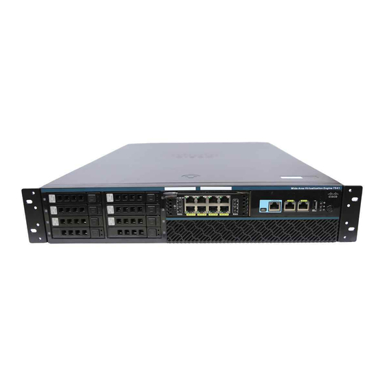
Cisco Wide Area Virtualization Engine 7541, 7571,
and 8541 Hardware Installation Guide
October 3, 2016
Cisco Systems, Inc.
www.cisco.com
Cisco has more than 200 offices worldwide.
Addresses, phone numbers, and fax numbers
are listed on the Cisco website at
www.cisco.com/go/offices.
Text Part Number:
Advertisement
Table of Contents
Troubleshooting


Need help?
Do you have a question about the 7541 and is the answer not in the manual?
Questions and answers