
Related Manuals for Avermedia NV 3000


Summary of Contents for Avermedia NV 3000
- Page 1 ® AVerMedia NV 3000/5000/6000E/6000E/7000H/9000E Digital Video Recording System User Manual Version 7.3...
- Page 2 TRADEMARKS AVerMedia, being authorized AVerMedia Information, Inc. to use, is registered trademarks of AVerMedia TECHNOLOGIES, Inc. IBM PC is a registered trademark of International Business Machines Corporation. Macintosh is a registered trademark of Apple Computer, Inc. Microsoft is a registered trademark and...
- Page 3 ® written permission of AVerMedia INFORMATION, Inc. Following information is only for EU-member states: The use of the symbol indicates that this product may not be treated as household waste.
-
Page 4: Table Of Contents
Table of Contents Chapter 1 Introduction..................2 NV3000 Package........................2 NV5000 Package........................2 NV6000 Package........................2 NV6000 Express Package.....................3 NV7000H Package ........................3 NV9000E Package ........................4 OSD kit (optional) ........................4 NV3000 Card Parts........................5 NV5000 Card Parts........................5 NV6000 Card Parts........................5 NV 6000 Express Card Parts....................6 NV7000H Card Parts ......................6 NV9000E Card Parts ......................7 IR USB Receiver Part &... - Page 5 NV6000 Express Hardware Installation..............17 2.6.1 Installing (2) NV6000 Express ................17 2.6.2 Installing (1) NV6000 Express and I/O card............17 NV7000H Hardware Installation .................18 2.7.1 Installing (1) NV7000H and I/O card ..............18 2.7.2 Installing (2) NV7000H and (2) I/O cards............18 NV9000E Hardware Installation .................19 2.8.1 Install NV9000 Express card................19 2.8.2...
- Page 6 Running the NV DVR Software ..................35 Using the Virtual Keyboard..................35 Familiarizing the Buttons in Preview/Advanced Mode ..........36 4.3.1 Using Event Log Viewer..................39 Familiarizing the Buttons in Compact Mode ...............40 Familiarizing the Buttons in Playback Mode...............41 4.5.1 Watermark Verification ..................44 Familiarizing the Buttons in PTZ Camera Controller ..........45 Setting Up and Using the Emap .................45 4.7.1 To Use the Emap ....................46...
- Page 7 Relay Setting ......................82 Alarm Setting ......................82 5.9.1 To Setup Alarm Relay: ..................88 5.9.2 To Setup the Alarm Sound Setting: ..............88 5.9.3 To Setup Call Out List: ..................89 5.9.4 To Setup Send E-mail Setting: ................89 5.9.5 To Setup FTP Setting:..................90 5.9.6 To Setup Alarm Recording Setting: ..............90 5.9.7 To Setup SMS/MMS Setting: ................92...
- Page 8 8.7.3 To Use the PDAViewer..................122 8.7.4 To Playback in PDAViewer................123 Using JavaViewer to Access NV DVR Server ............124 8.8.1 To install JAVAViewer from the DVR Server ...........124 8.8.2 To Use the JAVAViewer...................125 Chapter 9 Image Verification................127 To Run the ImageVerification program ..............127 Chapter 10 iEnhance ...................128 10.1 To Use iStable......................129...
- Page 9 Manual Conventions The following conventions are used throughout this manual. Caution symbol is intended to alert the user of the important installation and operating instructions. Fail to comply may damage the system. Information symbol is intended to provide additional information for the purpose of clarification.
-
Page 10: Chapter 1 Introduction
Chapter 1 Introduction AVerMedia AVerDVR is a 32-bit PCI video capture card that works as a digital video surveillance system. It enables you to capture true color images and real-time videos from 4 up to 16 camera inputs simultaneously. With the latest Motion Detection technology, you no longer need to monitor every single moment of the day;... -
Page 11: Nv6000 Express Package
NV6000 Express Package NV6000 Express package includes the following: (1) NV6000 (3) 2X AV cable (5) Installation CD (7) I/O cable (2) I/O card (4) Quick Guide (6) 30cm Watchdog line NV6000 Express OSD Kit (1) Remote Control (3) OSD Installation CD (batteries included) (2) IR USB Receiver (4) 2X Velcro Strips... -
Page 12: Nv9000E Package
NV9000E Package NV9000E package includes the following: (10) (11) (1) NV9000E (5) Quick Installation Guide (9) Audio transmitting cable (2) Daughter card (6) AV cable (10) Watchdog line (3) I/O card (7) AV cable (11) I/O cable (4) Installation CD (8) 3x Video transmitting cable OSD kit (optional) -
Page 13: Nv3000 Card Parts
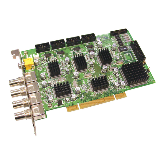
NV3000 Card Parts TV out link connector Audio pin TV out port I/O connector Reset pin video in ports Watchdog pin NV5000 Card Parts Video extension card connectors Display card connector TV out link Audio connector connector TV out port I/O connector Reset pin video in... -
Page 14: Nv 6000 Express Card Parts
NV 6000 Express Card Parts I/O connector DVI AV IN port 01 Reset pin DVI AV IN Watchdog pin port 02 NV7000H Card Parts TV out link connector Watchdog pin Reset pin TV out port I/O connector D-Type AV IN port Brand new power supply with at least 350W and 20A support at 3.3V is recommended for installation of NV7000H... -
Page 15: Nv9000E Card Parts
NV9000E Card Parts NV9000E Audio Transmitting Connector Video Transmitting Video Transmitting Connector Connector Power Connector VideoTransmitting Connector I/O Card Connector Watch Dog Pin Reset Pin Display 21 Card Connector NV9000E Daughter Card Video & Audio Transmitting Connector DVI AV In Port Display 21 Card Connector DVI AV In Port... -
Page 16: Ir Usb Receiver Part & Connection
IR USB Receiver Part & Connection USB Port IR sensor For detail of OSD kit installation, please refer to OSD kit Quick Guide. -
Page 17: Chapter 2 Hardware Installation
Chapter 2 Hardware Installation Minimum System Requirements First, must verify if the computer meets the minimum system requirements. NV3000/5000/6000/7000H: NV3000 NV5000 NV6000 NV7000H Pentium® 4 2.8GHz or above recommended Motherboard Intel 865, 875, 915, 925, 945, Intel 875, Intel 865, 875 955, NVIDIA nFORCE4 SLi - 915, 925, Chipset... - Page 18 64MB video memory Audio Sound card and speakers ® For AVerMedia Security Product Hardware Recommendation list update, go to http://www.avermedia.com/nvd/hardware-recom.asp. NV9000 EXPRESS: Motherboard Suggested motherboard in our website* Core2Duo E82 2.66Ghz VGA card Independent VGA card with 256MB ram...
-
Page 19: Nv3000/5000/6000(Exp)/7000H Hardware Combinations
NV3000/5000/6000(EXP)/7000H Hardware Combinations AVerMedia NV DVR provides powerful surveillance functions and flexible hardware combinations. The table shows the numbers of camera inputs, audio inputs, sensor inputs and relay outputs on different hardware combinations. Before installing the cards, the computer must be turned OFF, the power cable must be UNPLUGGED and all other cables that are attached at the back of the computer must be DISCONNECTED. - Page 20 NV6000 Express hardware combinations: Hardware Combinations Camera Audio Relay Sensor Input Input Input Output NV6480 Card IO Card Hardware Combinations Camera Audio Relay Sensor Input NV6240 Card IO Card Input Input Output (8Channels) Hardware Combinations Audio Camera Input Sensor Input Relay Output NV6240 Card IO Card...
-
Page 21: Nv3000 Hardware Installation
NV3000 Hardware Installation 2.3.1 Installing (1) NV3000 and (1) I/O Audio cards (optional) The I/O audio card is an optional item. The D-type I/O port receives and transmit signal from the I/O box where the sensor and relay device are connected to it, while the audio input port receives the signal from the mic. -
Page 22: Nv5000 Hardware Installation
20cm video signal line 20cm video signal line 20cm video signal line NV3000 card 1 NV3000 card 2 NV3000 Card 1 Card 2 Card 3 Card 4 NV3000 card 3 TV OUT TV OUT TV OUT TV OUT NV3000 card 4 IN 1 IN 1 IN 1... -
Page 23: Installing (1) Nv5000 And (3) Bnc Video Extension Cards
I/O Audio card NV5000 card NV5000 card I/O Audio card TV OUT IN 1 AUDIO IN 1 IN 2 AUDIO IN 2 IN 3 AUDIO IN 3 IN 4 AUDIO IN 4 2.4.3 Installing (1) NV5000 and (3) BNC video extension cards The BNC video extension card is an optional item. -
Page 24: Installing (2) Nv5000, And (2) Bnc Video Extension Cards
NV5000 card BNC extension card I/O Audio card BNC video extension I/O Audio NV5000 card card TV OUT IN 1 IN 1 AUDIO IN 1 IN 2 IN 2 AUDIO IN 2 IN 3 IN 3 AUDIO IN 3 IN 4 IN 4 AUDIO IN 4 2.4.5... -
Page 25: Nv6000 Express Hardware Installation
I/O card NV6000 I/O card NV6000 card AV connection cable TV OUT AV connection cable NV6000 Express Hardware Installation The NV6000 Express can support up to 16 cameras and 8 audio inputs 2.6.1 Installing (2) NV6000 Express The PC motherboard needs to have 2 PCI-Ex1 slots for installing 2 NV6000 Express card. -
Page 26: Nv7000H Hardware Installation
AV connection cable NV6000 Express card I/O card NV 6000 I/O card Express AV connection cable NV7000H Hardware Installation The supplied AV connection cable provides up to 16 cameras and 8 audio inputs. 2.7.1 Installing (1) NV7000H and I/O card Remove the PC case cover. -
Page 27: Nv9000E Hardware Installation
I/O card 1 NV7000H card 1 I/O card 2 NV7000H card 2 NV7000H NV7000H card 1 card 1 card 2 card 2 TV OUT TV OUT NV9000E Hardware Installation 2.8.1 Install NV9000 Express card Remove the PC case cover. Remove 1 bracket that cover the PCI slots and 1 bracket that cover the PCI-Ex1. Save the screws. -
Page 28: Install Nv9000 Express And Display 21 Card(Optional) And I/O Card
2.8.2 Install NV9000 Express and Display 21 card(optional) and I/O card Remove the PC case cover. Remove 3 brackets that cover the PCI slots and 1 bracket that cover the PCI-Ex1. Save the screws. Connect the Video and Audio transmitting cable to NV9000 Express card and NV9000 Express Daughter card. -
Page 29: Connecting The Watchdog Line To Nv6000
Reset SW lead Watchdog line NV3000 NV5000 2.9.2 Connecting the Watchdog line to NV6000 1. Look for the labeled RESET SW switch lead and connect it to the NV6000 card reset pin. 2. Connect the supplied Watchdog line to the NV6000 card watchdog pin and the other end to the motherboard RESET SW panel. -
Page 30: Connecting The Watchdog Line To Nv9000E
Reset SW lead Watchdog line NV7000H 2.9.5 Connecting the Watchdog line to NV9000E Look for the labeled RESET SW switch lead and connect it to the NV9000E card reset pin. Connect the supplied Watchdog line to the NV9000Ecard watchdog pin and the other end to the motherboard RESET SW panel. -
Page 31: Connecting The Cameras, A Tv And Audio Devices To Nv6000
NV3000 NV5000 I/O Audio I/O Audio card card MIC 4 MIC 3 MIC 2 MIC 1 AUDIO IN 1 AUDIO IN 1 AUDIO IN 2 AUDIO IN 3 AUDIO IN 4 2.10.2 Connecting the Cameras, a TV and Audio devices to NV6000 Use the supplied AV connection cable and connect it to the D-type AV IN port of NV6000 card (see NV6000 card... -
Page 32: Connecting The Cameras, A Tv And Audio Devices To Nv7000H
3. Connect one end of the RCA video cable (not supplied) to the TV OUT port of NV6000 Express card and the other end to the TV video input port. If you are not sure, please refer to the TV user manual. Camera 1 Camera 2 Camera 3 Camera 4... -
Page 33: Connecting The Cameras, A Tv And Audio Devices To Nv9000E
Camera 1 Camera 2 Camera 3 Camera 4 Camera 5 Camera 6 Camera 7 Camera 8 RCA cable Television NV7000H TV OUT MIC 1 MIC 2 MIC 3 MIC 4 MIC5 MIC6 MIC7 MIC8 AV connection cable 2.10.5 Connecting the Cameras, a TV and Audio devices to NV9000E Use the supplied AV connection cable and connect it to the DVI AV IN port of NV9000 Express daughter card (see NV9000E card... - Page 34 C amera 1 C amera 2 C amera 3 C amera 4 C amera 5 C amera 6 C amera 7 C amera 8 AV connection cable NV 900 0 E xpres s Daughter card MIC 1 MIC 2 MIC 3 MIC 4 MIC 5 MIC 6...
-
Page 35: 2.11 Dual Monitors Setup
2.11 Dual Monitors Setup The NV DVR system Supports Single and Dual monitor displays. When using dual monitors, the E-map and Playback function will be display on the second monitor. The Video configuration is different for each different VGA chipsets. Please follow the steps below to setup the dual monitors display. - Page 36 4. Select the Extended Desktop and then click Finish. 5. If user selected the Advanced mode, click the View button. 6. In Display Manager, right click on the second Display on the right side and select Extend Main onto monitor. 7.
-
Page 37: Graphic Card With Nvidia Chipset
2.11.2 Graphic card with NVIDIA chipset 1. Click the NVIDIA nView, and select the Dualview mode. 2. Adjust each monitor resolution to 1024x768, 1440x900, 1680x1050, or 1920x1200 3. To review if the display mode is correct, you can check the task bar. The task bar will show on the first monitor only. -
Page 38: 2.12 Connecting An External I/O Box To Nv3000/5000 I/O Card
2.12 Connecting an external I/O box to NV3000/5000 I/O card The external I/O box is an optional item. It provides four (4) sensor input and three (3) relay output. Connect the male end of the D-type cable to the D-type I/O port of the I/O box and the female end to the D-type port of the I/O card. -
Page 39: Connecting The Sensor/Relay Device To Nv6000 (Exp)/7000H/9000E I/O Card
2.13 Connecting the Sensor/Relay device to NV6000 (EXP)/7000H/9000E I/O card The I/O Audio card enables you to connect (4) sensor inputs and (4) relay outputs. Just connect the external sensor and relay pin directly to the NV6000/7000H I/O card pinhole. Check the table below and locate which pinhole is assigned to sensor input and relay output. -
Page 40: Connecting Pos (Point Of Sales)
AVerDVR can be integrated with POS system equipment. Connecting the POS ® equipment to AVerMedia AVerDVR system thru RS232 connection, enables you to view, record and keep track of the items that were sold. You may also select the camera on where to display all the data. -
Page 41: Chapter 3 Software Installation
For Windows 2000, make sure the hyper-threading setting is DISABLED from the PC BIOS system. To ensure getting the latest copy of NV DVR software, go and download the updated version from the following site: Worldwide : http://www.avermedia.com/cgi-bin/support_download.asp US/CANADA: (click on Support) http://www.aver.com... -
Page 42: Installing Nv Dvr Software And Drivers In Windows Xp/2000
Installing NV DVR Software and Drivers in Windows XP/2000 Upon turning the computer on, the system automatically detects the newly installed hardware. When the Found New Hardware dialog box appears, IGNORE it. It is important to install the NV DVR software first, before installing Remember : the drivers. -
Page 43: Chapter 4 Using The Nv Dvr Software
Chapter 4 Using the NV DVR Software Running the NV DVR Software To run the application, double-click on your PC desktop or click Start>Programs >DSS>NV DVR. For security purpose, some of the features would require you to enter User ID and Password before it can be accessed. -
Page 44: Familiarizing The Buttons In Preview/Advanced Mode
Familiarizing the Buttons in Preview/Advanced Mode NV DVR now supports 16:10 screen display (1920 x 1200, 1440x900, 1680x1050 resolution). (18) (17) (16) (15) (14) (13) (12) (19) (11) (10) Name Function (1) Exit Call up the Logout dialog box. In the logout dialog box, you may do the following: - Click Exit to close the NV DVR program. - Page 45 Name Function - Click Login to sign-in in different account. (1) Exit - Click Minimize to reduce the NV DVR to taskbar button. - Click Compact to switch to compact mode (see Chapter 4.4). - Click Guest to switch to the guest mode. In guest mode, the functions are limited to preview and playback function only.
- Page 46 Name Function (16) Full screen Use the entire area of the screen to only display the video. To return, press the right button of the mouse or ESC on the keyboard or click the arrow icon. Click the arrow icon to leave from full screen display mode...
-
Page 47: Using Event Log Viewer
4.3.1 Using Event Log Viewer Show the record of activities that take place in the system. 1. Click the Event Log button on DVR system main interface. The Event log viewer window will show up. 2. Select the Date to view or search certain event log by key word. Enter the key word in Find Text column and click Search button. -
Page 48: Familiarizing The Buttons In Compact Mode
Name Function (3) Channel Select the POS event log of channel Enter specific key word or word string to search the POS event log. (4) Search String Mark the “Match whole word exactly” box if wants to find exactly key word or word string of POS event log. -
Page 49: Familiarizing The Buttons In Playback Mode
Name Function (2) AutoScan Start/Stop video screen cycle switch (3) Alarm Alert and display warning info. (4) Playback Switch to Playback mode. This allows you to view the recorded video file. (see Chapter 4.5) (5) Advanced Switch to Preview/Advanced mode. Familiarizing the Buttons in Playback Mode To switch in Playback mode, click Playback button at the lower right corner of Advanced/Preview mode user interface. - Page 50 Name Function (3) Hour Buttons Select and click to playback the recorded video file on the specific time frame. The Hour buttons represent the time in 24-hour clock. The blue bar on top of the hour button indicates that there is a recorded video file on that period of time. While the red bar indicates that you are currently viewing the recorded video file.
- Page 51 Name Function (12) Full screen View in Playback-compact mode. To return, press the right button of the mouse or ESC on the keyboard or click the arrow icon. Click the arrow icon to escape from full screen display mode When you switch to full screen in multiple-screen mode, Left click to toggle to only display one of the video in the multiple-screen mode or all.
-
Page 52: Watermark Verification
4.5.1 Watermark Verification Now, NV DVR supports watermark-checking to identify the authenticity of playback video. NV DVR program can only verify when a single channel in full screen playback mode. To verify the playback video doesn’t been modified. Click to verify the playback video. Watermark verification windows will show up as following:... -
Page 53: Familiarizing The Buttons In Ptz Camera Controller
Familiarizing the Buttons in PTZ Camera Controller (see also chapter 4.13) Name Function (1) Close Exit PTZ camera controller. (2) Setup Configure PTZ cameras.(also see Chapter 4.13) (3) AutoPan Operate the PTZ cameras automatically based on the selected camera group preset position number. (4) Focus +/- Adjust the focus manually to produce clear image. -
Page 54: To Use The Emap
When the inserted map appears on the Emap screen, click Edit. You may now drag the camera, sensor, and relay icons to its place on the map. Icons on the map can be relocated anywhere. Right click camera icon can select the camera direction in 8 angles. If you are going to locate the icon on the map to other area, you need to drag the icon to the black pane at the bottom of the Emap screen and then switch to the area on where you want to locate the icon. -
Page 55: To Cut And Save The Wanted Portion Of The Recorded Video
Click Exit to close Emap screen. To Cut and Save the Wanted Portion of the Recorded Video Use the Playback Control buttons or drag the bar on the playback progress bar and pause on where you want to start the cut. Then, click Segment to set the begin mark. Use the Playback Control buttons or drag the bar on the playback progress bar and pause on where you want to end the cut. -
Page 56: To Search Using The Visual Search
When the bookmark is protected, the file won’t be overwritten. The protected bookmark file will be deleted when the Delete the recorded data is enable in the System setting.(also refer to 5.1 System setting) Select and click one in the bookmark list to preview the file. To Search Using the Visual Search Click Visual Search. -
Page 57: 4.11 To Search Using The Intelligent Search
4.11 To Search Using the Intelligent Search 1. Click on the video screen on where you want to search. 2. Click Intelligent Search. The Intelligent Search text (red) would appear at the lower left corner of the screen. 3. When the Intelligent Search Setting dialog box and motion detector frame appear, you may adjust the sensitivity bar and the motion detector frame size and location. - Page 58 In the Connection Settings section, select the COMPort where the PTZ camera is connected, PTZ ID number and PTZ camera protocol. Then, click Save to keep the settings. Use the PTZ control panel and adjust the position of the PTZ camera. In the Preset Setting section, select the preset number to assign a number for the PTZ camera current position.
-
Page 59: Setup The Ip Ptz Camera
When is done, click OK to save the setting or Click Cancel, to leave without saving the new setting. 4.12.2 Setup the IP PTZ Camera 1. In the PTZ control panel, click Setup. 2. When the PTZ Setup dialog box appears, click IP PTZ tab. 3. - Page 60 8. Restore AutoPan Time: set a time period for restoring auto path function after the IP PTZ camera has been moved. Mark the check box and set the time period in second. 9. Click Advanced Settings to enable the on screen PTZ control function. Mark Enable check box to enable the control arrow and tools on the Preview screen.
-
Page 61: Chapter 5 Customizing The Nv Dvr System
Chapter 5 Customizing the NV DVR System In the Preview/Advanced screen mode, click button to customize your NV DVR. When the NV DVR configuration setup selection appears, select and click the buttons you want to change the setting. System Setting In the System Setting dialog box, click OK to accept the new settings, click Cancel to exit without saving, and click Default to revert back to original factory setting. - Page 62 In the Map Network Drive windows, select the Drive and fill in the network drive direction in Folder column if you know. Or click Browse to find the folder direction. Click Finish to complete the network drive mapping. After the network drive has been added, user needs to create a folder for network storage.
- Page 63 (3)Language Customize the system to display the tool tips and dialogs based on the selected language. By default the language is in English. (4) Video Standard Change and select the proper video system according to your camera video system. If the video system setting is wrong, the video would appear abnormal.
- Page 64 Fixed Layout (1) Select the video card channel from drop down list. If user only installs one NV card on the computer, then, there is only one video card channel for selection. (2) Select the display mode as FixedLayout. (3) Preview screen: the selected camera video will preview in here. (4) Video Mode: Select the split mode of TV out display.
- Page 65 Enable – Mark the check box to enable the System Controller function. Model – Select model of the System Controller. Port – Select the com port that is connected with the System Controller. Click Setup to configure com port value. The com port value is shown in below table: 9600 Baud rate Data bits...
- Page 66 4. Click OK to save the configuration. IP Setup Obtain an IP automatically (DHCP): To use DHCP server assigning DVR server a IP address. Using the following IP address: Assign a fixed IP address for DVR server IP ADDRESS: Assign a constant IP address which a real IP addresses give from ISP to DVR system.
- Page 67 Automatically log in to the selected default user when the NV DVR is executed. (11) Miscellaneous Enable the conditions in Miscellaneous section you want the system to perform. Status Report Send a daily system event and attention analysis report. To change the e-mail settings, click Setup.
-
Page 68: To Set The Pos Setting
Set from which camera screen to display the data from the POS equipment. Click Setting, to set the POS Console Setting. To set the text flow and color format, click Advanced. (see also Chapter 5.1.1) (13) Dual Monitor Enable/disable dual monitor display. Click Setting to select the dual monitor display mode. (14)UPS (Uninterruptible Power Supply) Protect the system from damaging, such as power surges or brownouts. - Page 69 : Enter a name to identify the POS. (1) POS Name : To select the protocol, click Setting button (see Setup POS (2) Protocol Protocol) : Set the number of lines you want to be removed (3) Skip first : Click to test POS setting. You will see a test result on the right (4) Start Testing side of POS Mapping window.
- Page 70 : Select the Local or Remote port to where it is connected. (6) Port Setting Local - select the COM port number which is connected. Remote – Use the UDP protocol for remote connection if POS system can broadcast to Internet. Enter the IP address of the remote station.
-
Page 71: Setup Pos Device
Setup POS Device There are 4 default POS devices. If user uses the POS device beside defaults, user can add new POS device and rules. The POS device can be added up to 50 include defaults. Setup Standard POS Device •... - Page 72 5. Enter the string or character as the rule in Data column. The maximum length is 31 characters. 6. Click OK 7. Click Save. The configuration will be lost without saving. 8. To modify existing replace rules, double click it. •...
- Page 73 Setup XML POS Device XML can only work with the POS data is transmitting in XML format. Device: select or add a new device. Only device that supports XML can be configured in here. Click Add to add a device. Enter device name and select Type as XML. The POS device can be added up to 50 include defaults.
- Page 74 Please refer to the following example for more detail. <TicketStart> → Page Start <Header> → Root tag <MessageVersion>1.0</MessageVersion> <Date>20060317</Date> <Time>164216</Time> <RegisterID>3</RegisterID> → Sub tag <Shift>4</Shift> <CashierID>000000009</CashierID> <JrnlTransNum>3</JrnlTransNum> <JrnlID>0</JrnlID> </Header> </TicketStart> <Item> <SaleTotals> <Item> <SaleTotals> <Item> <SaleTotals> <TenderEvent> <TicketComplete> → Page End...
-
Page 75: Camera Setting
Camera Setting In the Camera Setting dialog box, click OK to accept the new settings, click Cancel to exit without saving, and click Default1/ Default2 to revert back to original factory setting. (10) (11) (1) Camera Icons Select the camera number you want to adjust the video setting. To select all the cameras, enable the ALL check box. - Page 76 is selected. (2) Enable Set to enable/disable the selected camera. When there is no video source on the camera, we suggest disabling it so that the system won’t detect it as video loss error. (3) Camera Display Enable/disable to show the video. Even if the video of the selected camera is hidden you can still record the video and preview it in playback mode.
- Page 77 In Camera Setting interface, click Detail to configure Video, Senor, Relay, and Direct Link by IE of the IP camera. Video Setup Adjust the video setting of the selected camera. Click Video Setting to enter video adjustment interface. - Video Setting Adjust the Frame Rate, Quality, Bright, Contrast, Hue, and Saturation.
- Page 78 Relay Setting To setup relay device that is embedded on the camera. Click the drop-down list and select the relay ID number. Enter relay name in Name column The DVR system automatically detects the camera and input relates information. In the Content section, enter relay description. In the test section, click Test to trigger relay.
-
Page 79: Setup The Object Counting
5.2.1 Setup the Object Counting Click Detail to enter the object counting setup window. Enable Detected Regions in Display section. This enables the object counting information show on the screen. Moving Object will enable the object size frame to show on the screen. -
Page 80: Recording Setting
Recording Setting In the Recording dialog box, click OK to accept the new settings, click Cancel to exit without saving, and click Default to revert back to original factory setting. (10) (11) (1) Camera Icons Select the camera number you want to set the recording setting. To select all the cameras, enable the ALL check box. - Page 81 No Recording The system won’t do any recording. (3) Enable Audio Select to assign the audio channel of the selected camera. You can only assign one audio channel to one camera source. This way you can record both audio and video. An Audio I/O card is required to use this function.
- Page 82 MPEG 4 H264 H264 MJPG Encryption Encryption NV 3000 NV 5000 NV 6000 NV 6000 Express NV 7000H Using the Advanced MPEG4 enables you to encrypt the recorded video that way only the person who knows the password can clearly view the video playback. The file size would become 10 to 30% more.
-
Page 83: To Mask/Shield An Area On The Screen
5.3.1 To Mask/Shield an area on the screen: In the Mask/Shield Edit section, activate the Enable Mask/Enable Shield check box. In the Edit section, select between Mask or Shield and click the button. Click and drag a frame on the (9) Video Screen to create Mask or Shield area. 5.3.2 To show and change the color of the Mask Enable the Show Mask check box. - Page 84 it accessible via internet using WebViewer, Remote Console, PDA Viewer and Hand Viewer (still image). To select all the cameras, enable the ALL check box. (3) Main Configuration Set the Server IP and Remote Console Port number. The system will automatically detect your Server IP address.
- Page 85 Enable HandyViewer Enable remote users to use a PDA or a mobile phone to access NV DVR server and select the video size and quality. (See also Chapter 8.5 and 8.6) Network Bandwidth Limit By Channel: Set the network bandwidth by each channel. All: Set the total network bandwidth consumption limit.
-
Page 86: Schedule Setting
Schedule Setting Schedule to record, backup, enable network, reboot and disable alarm of all the cameras either weekly or one time. The number from 00 to 23 represent the time in 24-hour clock. The left most column display the days in a week. To Set the Schedule Setting: 1. -
Page 87: To Set Schedule At A Specific Portion Of Time In That Hour
5.5.1 To set schedule at a specific portion of time in that hour: Right click the colored blocks. In the Select time dialog box, click to enable or disable the portion you want to set. Click OK to accept the setting and Cancel to exit without saving the setting. -
Page 88: Backup Setting
Backup Setting In the Backup Setting dialog box, the number from 00 to 23 represent the time in 24-hour clock. The numbers from 01 to 16 represent the camera number. When you back up the file, you may find Qplayer application included in the backup folder (see also Chapter To Backup file: 1. -
Page 89: Sensor Setting
9. Click to start archiving the selected file. 10. In the Processing… dialog box, to stop archiving press Abort. When done, in the Backup Path list, shows the archived item. To burn the file in CD, you need to have NERO 6 or above installed in your PC then select the item in the list and click Burn. -
Page 90: Relay Setting
Relay Setting The I/O device must be installed to use this function. To set the Relay Setting: 1. Click the drop-down list and select the relay ID number. 2. Enter relay name. 3. The system automatically detects the card and input number. - Page 91 1. Click Add to insert and set a new alarm setting. Click the items in the (7) Alarm Setting List, if you want to modify the alarm setting. 2. In (1) Alarm Setting number/Name/Description, display the selected alarm setting number in the list below. Enter alarm name and description. 3.
- Page 92 • Normal Reboot: when the NV DVR system reboot without abnormal condition, the system will send out the alarm message. • Abnormal Reboot: when the NV DVR system reboot in irregular condition, the system will send out the alarm message. •...
- Page 93 6. In (5) Alarm Reset, click the camera number (use to select the alarm) to set the reset condition of alarm. Once alarm is reset, all alarm action will stop at the moment. If the sensor normal status is high, set the sensor condition to low. To set sensor status of IP camera, click IP Camera Sensor.
- Page 94 Enlarge Camera View Switch to only display video in Preview/Advanced mode from where the alarm is activated. a. Select the camera from drop down list to specify which camera video to be enlarged on screen when the alarm is triggered. Alarm Camera: when a channel has an alarm occurred, and then, the channel video that has an alarm occurred will be enlarged on screen.
- Page 95 5.9.6). SMS (Short Message Service)/MMS (Multimedia Messaging System) SMS transmits only text messages to mobile phone. MMS transmits text messages and images over wireless networks using the wireless application protocol (WAP). Make sure your mobile phone support this feature and your PC is connected to GSM/GPRS modem.
-
Page 96: To Setup Alarm Relay
5.9.1 To Setup Alarm Relay: 1. Beside the Relay Output check box, click Detail. 2. In the Alarm Relay dialog box, select from the available relay list and in the ON column, set to enable/disable the relay operation when the alarm is activated. In the Retrieve time check box, you may enable/disable to extend the relay operation time and set the duration in second. -
Page 97: To Setup Call Out List
5. Click OK to exit and accept the setting and Cancel to exit without saving the setting. 5.9.3 To Setup Call Out List: 1. Beside the Make Phone Calls check box, click Detail. 2. In the Call Out List, click Add to insert a new contact number, Modify to edit the selected item, Remove to delete the selected item, Test to check if it is working. -
Page 98: To Setup Ftp Setting
To check if it is working, click Test Account button. Enter the sender e-mail address. From: To and CC: Enter the recipient email address and separate it with comma or a semicolon (;). Enter the message title. Subject: Type the message. Message: (3) Email Notice Setting Notice Interval: Set the period of time before it sends another e-mail notice. - Page 99 Click OK to accept the new settings and Cancel to exit without saving.
-
Page 100: To Setup Sms/Mms Setting
5.9.7 To Setup SMS/MMS Setting: To use this feature, GSM/GPRS modem is required. Connect the GSM/GPRS modem to the serial COMM port of PC. Beside the SMS/MMS check box, click Detail. MMS module is developed by ActiveXperts Software B.V. Select the port number in ComPort drop down list from where the GSM/GPRS modem is connected. -
Page 101: To Setup Alarm Sop
5.9.9 To Setup Alarm SOP: Beside the Alarm SOP check box, click Detail. In the step text boxes, type the standard protocol when the alarm is activated. When the alarm is activated, the Standard Operation Procedure dialog box will appear. Just click Next to see the next instruction, Back to see the previous instruction, Finish to end and Abort to terminate. -
Page 102: Missing, Suspicious Object, And Scene Change Detected
5.9.12 Missing, Suspicious Object, and Scene Change Detected Missing Object Select the certain object on the screen for the system to detect; when the object is disappear or move and the system will alarm. Click OK to exit and save the configuration. To exam the setup condition, click Start Test. - Page 103 and drag the frame on the screen. Enable Mask Mark an area on the screen to disregards the motion in the marked area and to only monitor outside the marked area. Mark the Enable Mask check box, click and drag the mask frame on the screen. To reset all object frames, click Clean.
-
Page 104: 5.10 User Setting
5.10 User Setting Only administrator can access User Setting. The maximum user accounts are 256. In the User Setting dialog box, click Add to insert a new user, Delete to remove the selected user, Edit to modify the user control right, OK to exit and accept the setting, and Cancel to exit without saving the setting. - Page 105 (1) Authorization level Select the status of the user. Only Administrator-level can access User Setting, and reset the Alarm status when using the Remote Console. (2) Control Right Enable the items that would allow the user to access. (3) Web Viewer Enable/disable Web Viewer control right that allow the user to operate from a remote location using internet explorer.
- Page 106 (6) Name Enter the user name. (7) Description Enter the user description. (8) Password Enter the user password. (9) Confirm Password Enter the same user password for confirmation.
-
Page 107: Chapter 6 Backup Video Players
Chapter 6 Backup Video Players You can playback the backup files using QPlayer applications. When you back up the recorded file, QPlayer applications are automatically included in the backup folder. With QPlayer, it is the same as in Playback mode and supports six (6) different split screen types to view all the video at the same time. - Page 108 Name Function Begin: Move at the beginning of the recorded video file. (4) Playback Previous: Go back to the previous frame. Control Slower: Play the recorded video file at the speed of 1/2X, 1/4X, or Buttons 1/8X. Rewind: Wind back the recorded video file. Pause: Briefly stop playing the recorded video file.
- Page 109 Name Function (11) Full screen View in Playback-compact mode. To return, press the right button of the mouse or ESC on the keyboard or click the arrow icon. Click the arrow icon to escape from full screen display mode When you switch to full screen in multiple-screen mode, Left click to toggle to only display one of the video in the multiple-screen mode or all.
-
Page 110: Chapter 7 Using Functional Keys
Chapter 7 Using Functional Keys The NV DVR system provides shortcut keys. The table shows the function keys and descriptions. Function Keys description Exit System Display system information Start recording Enable network function Access system settings Switch to playback mode Access E-map setting Access PTZ camera control panel Snapshot... -
Page 111: Chapter 8 Using The Remote Programs
Chapter 8 Using the Remote Programs You can use Microsoft Internet Explorer to access NV DVR server by entering the IP address or domain name. To use this feature, make sure that you are connected to the internet and the Network feature is enabled. -
Page 112: Familiarizing The Nv Dvr Webviewer Buttons
Familiarizing the NV DVR WebViewer Buttons Right-clicking on the webcam video screen, enables you to start video recording, change video quality, switch camera and enable/disable DirectDraw. (15) (14) (13) (12) (11) (10) Name Function (1) DirectDraw Enhance the video quality. Not all graphic cards can support this function. - Page 113 Name Function (12) Select a PTZ Initiate PTZ camera controller (see also Chapter 8.2) camera (13) Snapshot Capture and save the screen shot in *.bmp format. (14) Full screen Use the entire area of the screen to only display the video. To return, Right click the mouse or press ESC on the keyboard.
-
Page 114: To Setup Remote System Setting
8.1.1 To Setup Remote System Setting Click OK to exit and save the setting and Cancel to exit without saving the setting. The setting here applies to Remote DVR only. (10) (11) (12) (13) (14) (1) Camera Name Select the camera you want to adjust the settings. (2) Enable Set to enable/disable the selected camera. - Page 115 Motion Recording Start recording the video from the selected camera only when the system detects motion. Once a motion is detected, the system automatically saves the previous frames and stop based on the Start Record Prior and Stop Record After settings. Smart Recording Automatically switch to recorded at the maximum frame rate setting once a motion is detected and if there is no motion, it records at the minimum frame rate setting Set the...
-
Page 116: Familiarizing The Webviewer Ptz Buttons
Familiarizing the WebViewer PTZ Buttons Name Function (1) Direction buttons Adjust and position the focal point of the PTZ camera. Click the center to pan automatically. (2) Select PTZ Choose to enable/disable the PTZ camera. In the Select PTZ dialog box, Select column, click to enable/disable viewing and controlling the PTZ camera. -
Page 117: Familiarizing The Remote Console Buttons
Familiarizing the Remote Console Buttons (17) (16) (15) (14) (13) (12) (11) (2)(3) (10) Name Function (1) DirectDraw Enhance the video quality. Not all graphic cards can support this function. (2) Exit Close the Remote Console. (3) Volume Enable/disable the sound. (4) Split Screen Select from six (6) different split screen type to playback the Mode... -
Page 118: To Setup Remote Console Setting
Name Function (13) Camera ID Show the number of cameras that are being viewed. When you are in single screen mode, click the camera ID number to switch and view other camera. (14) Event log Show the record of activities that take place in the system. To filter the records, select and click the option button to only display Event, System, Operation, Network or POS. -
Page 119: Familiarizing The Buttons In Ptz Camera Controller
Familiarizing the Buttons in PTZ Camera Controller (11) (10) Name Function (1) Close Exit PTZ camera controller. (2) Setup Configure PTZ cameras.(also see Chapter 4.13) (3) AutoPan Operate the PTZ cameras automatically based on the selected camera group preset position number. (4) Focus +/- Adjust the focus manually to produce clear image. -
Page 120: Using The Remote Playback
Using the Remote Playback To use this feature, first you need to select the source of the file. In the Select Playback Mode dialog box, choose Local Playback to open the file that is recorded in the Remote Console, and Remote Playback to open the file that is recorded in the NV DVR server. When you choose Remote Playback, select RealTime Playback if your internet bandwidth is fast and big enough, otherwise choose Download and Playback. -
Page 121: Familiarizing The Local Playback Buttons
8.5.1 Familiarizing the Local Playback Buttons (15) (14) (13) (12) (11) (10) (4) (5) Name Function (1) Split Screen Mode Select from six (6) different split screen types to playback the recorded video file of all the camera, or one camera over the other or alongside on a single screen. - Page 122 Name Function (3) Hour Buttons Select and click to playback the recorded video file on the specific time frame. The Hour buttons represent the time in 24-hour clock. The blue bar on top of the hour button indicates that there is a recorded video file on that period of time. While the red bar indicates that you are currently viewing the recorded video file.
- Page 123 Name Function Seconds and Second. (See also Chapter 4.10) (14) Find Next Search for the next event or changes in the motion detector frame. You can use this when you are using Intelligent Search or Event Search function. (15) Intelligent Search Search the changes in the motion detector frame (See also Chapter 4.12).
-
Page 124: Familiarizing The Realtime Playback Buttons
8.5.2 Familiarizing the RealTime Playback Buttons (11) (10) Name Function (1) Split Screen Select from two (2) different split screen type to playback the Mode recorded video file of all the camera, or one camera. - If there are only 4 cameras, you won’t be able to switch to 9, 16, and 13 split screen mode. - Page 125 Name Function (4) Playback Begin: Move at the beginning of the recorded video file. Control Buttons Previous: Go back to the previous frame. Slower: Play the recorded video file at the speed of 1/2x, 1/4x, or 1/8x. Rewind: Wind back the recorded video file. Pause: Briefly stop playing the recorded video file.
-
Page 126: Familiarizing The Download And Playback Buttons
8.5.3 Familiarizing the Download and Playback Buttons (11) (10) (4) (5) Name Function (1) Split Screen Select from six (6) different split screen types to playback the Mode recorded video file of all the camera, or one camera over the other or alongside on a single screen. -
Page 127: Using Handyviewer To Access Nv Dvr Server
Name Function The numbers from 00 to 23 represent the time in 24-hour clock. The numbers from 01 to 16 represent the camera ID. The blue colored column indicates that there is a recorded video file on that period of time. While the red colored column indicates on where to start playing the recorded video file. -
Page 128: Using Pdaviewer To Access Nv Dvr Server
Using PDAViewer to Access NV DVR Server Users can also use a PDA to access the NV DVR through Internet. Make sure your PDA support IE browser and is connected to the internet. To use this feature, you need to install the PDA Viewer software either thru ActiveSync connection or download it from the internet. -
Page 129: To Install Pdaviewer From The Internet
5. When done, click OK. 8.7.2 To install PDAViewer from the Internet Make sure you are connected to the internet. 1. Open the web browser and enter the server IP. Then click the hyperlink Download PDAViewer. 2. When the Download dialog box appears, enable Open file after download and click Yes. -
Page 130: To Use The Pdaviewer
8.7.3 To Use the PDAViewer 1. Run the PDAViewer in the Programs. 2. Familiarizing the PDAViewer buttons. (10) Name Function (1) Connect Hook up to the NV DVR server. Make sure you are connected to internet. When the iView screen appears, click Add to add DVR server. Enter the server IP, port, user ID, password and select the connection type. -
Page 131: To Playback In Pdaviewer
Name Function Mode and view different camera number or channels. (3) About Display the PDAViewer software version. (4) Minimize Reduce the size to taskbar. (5) Exit Close the PDAViewer. (6) Focus Adjust the focus of PTZ camera to produce clear image. (7) Full Screen Use the entire screen to only display the video. -
Page 132: Using Javaviewer To Access Nv Dvr Server
On the playback screen, tap on video screen longer the pop up menu will appear Select the Remote IO 10. The sensor and relay devices will list as below: 11. User can change the relay status. Select the relay and tap on video screen longer the pop up menu will appear, and then, select the status (ON, OFF, Tigger) Using JavaViewer to Access NV DVR Server Using the mobile phone within Symbian Smart Phone OS to access the NV DVR through... -
Page 133: To Use The Javaviewer
8.8.2 To Use the JAVAViewer Run the JAVAViewer program. Enter the DVR IP address, port number, user ID, and password. Please refer to your DVR server setting for that information. And then, select the Connect to connect to DVR server. Click Yes to accept the data from DVR server. - Page 134 To switch to different camera view, select menu and select the channel. The JAVAViewer support PTZ control function, you can refer to Help file for detail function control key. Select menu and go the way down to select the Help →...
-
Page 135: Chapter 9 Image Verification
Chapter 9 Image Verification ImageVerification is a watermark-checking program to identify the authenticity of a saved image (e.g. by snapshot). This program can only verify uncompressed bmp image files. To Run the ImageVerification program 1. Click Start>Programs>DSS>ImageVerification. 2. In the ImageVerification screen, click Load Source Image and locate the image source. 3. -
Page 136: Chapter 10 Ienhance
Chapter 10 iEnhance The bundled iEnhance is a video editing tool and can only be used with *.dvr video file. It allows you to adjust the video picture quality, segment and save the wanted portion of the video, zoom in and out the image, and print or save the screen shot. You can also save the setting and apply it on other files. -
Page 137: 10.1 To Use Istable
Name Function (13) Sharpness Improve the overall image by enhancing edges. This gives the image more depth. • Gray Scale: convert the image into black and white (monochrome). (14) Effects • Normalize: adjust the brightness intensity. • Equalize: automatically adjust the images that are too dark. •... -
Page 138: Chapter 11 Web Tools
Chapter 11 Web Tools The bundled Web Tools includes Dispatch Server and Remote Backup program. To install Web Tools, place the CD into the CD-ROM drive then click Install Web Tools. 11.1 Dispatch Server Dispatch is designed to reduce the network traffic of the NV DVR server. Instead of connecting directly to the NV DVR server, the client can connect to the computer that is connected to the NV DVR server using the Dispatch program. -
Page 139: 11.2 Remote Setup
11.2 Remote Setup Remote Setup is a tool for configuring DVR server from remote site. To install Remote Setup application, insert the Installation CD into CD-ROM drive and click Web Tools. After installation, click to start the Remote Setup application. 11.2.1 To Add DVR server User need to add a DVR server and make connection in order to setup remote DVR server. -
Page 140: To Setup Remote Dvr Server
8. User also can import the setting by clicking Import button. To save the setting to local hard disk, click Export button. 11.2.2 To Setup Remote DVR Server Select the DVR server from listing and click Setup to configure remote DVR server. System Setting In the System Setting windows, click Update to accept the new settings, click Exit to exit without saving, and click Default to revert back to original factory setting. - Page 141 (5) TV Out Set the display time gap from 3 to 10 sec. before it switches to the next camera. (6) Miscellaneous Enable the conditions in Miscellaneous section you want the system to perform. - Beep if no signal Make sound when the video signal is lost. - Mandatory Record Always record video when software is running - Playback Mode...
-
Page 142: Camera Setting
The UPS application must meet Windows 2000 or Windows XP system requirements. (10) Virtual Keyboard If the keyboard is not available, you may use the Virtual Keyboard. Just click to show the virtual keyboard. For uppercase and lowercase, click shift button. Camera Setting Select the camera from remote DVR servers to modify settings. -
Page 143: Record Setting
Noise Reduction uses lots of CPU resource. Please use this feature only if it is really necessary. (6) Auto Brightness Control Automatically adjust the brightness. (7) Night View Automatically adjust the exposure to make the image more visible especially when the site is dark. - Page 144 MPEG4 uses higher compression rate and smaller file size. While MJPEG uses slightly lower compression rate and bigger file size. MPEG4 MPEG 4 H264 MJPG Encryption NV 3000 NV 5000 NV 6000 NV 6000 Express NV 7000H...
-
Page 145: Network Setting
Network Setting In the Network Setting dialog box, click Update to accept the new settings, click Exit to exit without saving, and click Default to revert back to original factory setting. For the network service ports that use by DVR server, please see Appendix (10) (1) Server Name... -
Page 146: Schedule Setting
Adjust the NV DVR system time same as network time server. Fill in the Time Server IP address or domain name. Select Automatic Synchronize time to set automatic synchronize time on a daily basis. (9) Other Configuration - UPnP Enable UPnP function to automatically configure the port setting on the local network. This function is available when there is UPNP device in the same network. -
Page 147: Alarm Setting
left most column display the days in a week. To Set the Schedule Setting: 1. Select the date in the calendar. Use buttons to shift the calendar to the left or right. 2. Select the condition you want to schedule in the drop down list. Record Activate all the cameras to start video recording at the set time based on the Recording setting (see also... - Page 148 To set the Alarm Setting: Click Add to insert and set a new alarm setting. Click the items in the (7) Alarm Setting List, if you want to modify the alarm setting. 2. In (1) Alarm Setting number/Name/Description, display the selected alarm setting number in the list below.
- Page 149 • Hard Disk failed: when the hard disk can’t work normally, the system will send out the alarm message. • Temperature: set a temperature limited of system for system to alarm. When DVR system temperature is over the temperature limited, the system will send out the alarm.
- Page 150 Enable/disable the selected camera to send video to CMS when the alarm is activated (see also To Setup CMS Setting) Snapshot Take a snapshot when the alarm is activated. a. Select specify which Camera: channel video to be snapshot when the alarm is occurred.
- Page 151 the system will capture the image and send the image to the certain e-mail address with the alarm message. (4) Modem Dial up Setting User may set the time to disconnect automatically, just enable the Auto Disconnect after check box and set time. To Setup FTP Setting: Beside the File Transmission via FTP check box, click Detail.
-
Page 152: 11.3 Remote Backup
Back to see the previous instruction, Finish to end and Abort to terminate. To Setup CMS Setting Beside the Send to CMS check box, click Detail. In the CMS Setting, select the camera to enable/disable sending the video to CMS. Enable All to select all cameras. - Page 153 5. Select the Backup mode: Auto Backup mode: the backup will automatically execute when the setup is completed In Begin Date drop down calendar, select the date from where to start Click Add to set the storage path. Click Delete to remove the selected storage path. Click Schedule to select/unselect the time you want to backup.
- Page 154 7. Click Start to begin backup and click Stop to stop backup progress. While backup, the Start button will turn to Stop button 8. For manually backup, click file select button and select the DVR wants to backup.
-
Page 155: Chapter 12 Using The Remote Control Server
Chapter 12 Using the Remote Control Server The bundled Remote Control Server enables the PC with Central Management System program (CM3000) installed in it remotely access the NV DVR server. You may need to manually run this program for CMS access the NV DVR server. To run, click Start > Programs >... -
Page 156: Appendix A Registering Domain Names
Password, E-mail, Company, and Country. And then, click OK to complete the domain name registration. Note that Host Name and Domain Name (AVerMedia.avers.com.tw) are the replacement for Internet address while a remote client tends to search a... -
Page 157: Appendix B Configure Upnp
Appendix B Configure UPnP NV DVR application support UPnP function that can automatically configure the port setting to the local router. Please make sure the following items are true for the UPnP to work able: Window XP service Pack 2 is require Window XP must be configured to use UPnP UPnP must be enabled on your router (Please contact your local router dealer or refer to the router user manual for the UPnP configuration on router) - Page 158 Mark the UPnP Framework check box and click OK.
-
Page 159: Appendix C Network Service Port
Appendix C Network Service Port The following table shows the ports that DVR server uses for certain network service. Port # Variable 5550 Remote Console (CM 3000) WebCam 9999 2-way audio 5555 Remote Control (CM3000/RC1000) 5150 DVR POS 53 / 1053 DVR DDNS (Upload / Download) -
Page 160: Limited Warranty
LIMITED WARRANTY AVerMedia TECHNOLOGIES, Inc. warrants that this product to be free of defects resulting from faulty manufacturing or components under the following terms: WARRANTY LENGTH Labor is warranted for 15 months from the date of purchase. Replacement products will be warranted for the remainder of the 15-month warranty period or 30 days, whichever is longer.
Need help?
Do you have a question about the NV 3000 and is the answer not in the manual?
Questions and answers