
Related Manuals for Kontron ePCI-101


Summary of Contents for Kontron ePCI-101
- Page 1 User’s Guide Half Size SHB Based on Pentium-M Document Revision 1.2 Ref. : M8005_TECH_2/ July 2005...
-
Page 2: Customer Service
Kontron, nor the rights of others. Kontron is a registered trademark of Kontron. All trademarks, registered trademarks, and trade names used in this user’s guide are the property of their respective owners. -
Page 3: Table Of Contents
2.3.5 Audio Interface ..................2-10 Super I/O ....................2-11 2.4.1 Floppy Connector(J3) ................2-11 2.4.2 Multifunction Connector(J7) ..............2-12 2.4.3 Serial Ports .................... 2-13 2.4.4 Parallel Port (J6) ..................2-15 Ethernet Controllers (J12 and J14) ..............2-17 ePCI-101 User’s Guide... - Page 4 Installing Drivers..................4-20 4.2.1 Video Drivers..................4-20 4.2.2 Ethernet Drivers..................4-20 4.2.3 Other Drivers..................4-20 Console Redirection (VT100 Mode) ..............4-21 4.3.1 Requirements..................4-21 4.3.2 Setting Up and Configuring............... 4-21 4.3.3 Running Without a Terminal ..............4-22 ePCI-101 User’s Guide...
- Page 5 Memory & I/O Maps ....................A-1 Memory Mapping ..................A-1 I/O Mapping ....................A-2 Interrupt Lines ....................B-1 IRQ Lines ....................B-1 Kontron Extension Registers .................. C-1 FPGA/CPLD Registers Definition ............... C-1 Registers Summary ..................C-1 LANS and Serial Buffers Control ............... C-2 Reset history and CpuFault ................C-2 History Clear....................
- Page 6 Power Supply Does Not Stop (Softoff Does Not Work)........H-2 H.4.2 Bad Behavior Following an AC loss ............H-2 H.4.3 SHB Stuck in Reset ................H-2 H.4.4 SHB Hang During Boot ................H-3 Off-board PCI Problems ..................H-3 H.5.1 Bus A Problems ..................H-3 A.1.1 IDE Problems....................H-3 Getting Help ....................... I-1 ePCI-101 User’s Guide...
-
Page 7: Safety Instructions
Safety Instructions Contents Before You Begin ............vii When Working Inside a Computer ........viii Preventing Electrostatic Discharge ........ix Working with Batteries............x ePCI-101 User’s Guide... -
Page 8: Before You Begin
♦ Use extreme caution when installing or removing components. Refer to the installation instructions in this user’s guide for precautions and procedures. If you have any questions, please contact Kontron Technical Support. WARNING High voltages are present inside the chassis when the unit’s power cord is plugged into an electrical outlet. -
Page 9: When Working Inside A Computer
Also, before connecting a cable, make sure both connectors are correctly oriented and aligned. CAUTION Do not attempt to service the system yourself, except as explained in this user’s guide. Follow installation and troubleshooting instructions closely. viii ePCI-101 User’s Guide... -
Page 10: Preventing Electrostatic Discharge
Static electricity can harm system boards. Perform service at an ESD workstation and follow proper ESD procedure to reduce the risk of damage to components. Kontron strongly encourages you to follow proper ESD procedures, which means using wrist straps and smocks, when servicing equipment. -
Page 11: Working With Batteries
♦ Do not heat or incinerate ♦ Do not charge ♦ Do not deform or disassemble ♦ Do not apply solder directly ♦ Do not mix different types or partially used batteries together ♦ Always observe proper polarities ePCI-101 User’s Guide... - Page 12 Batterietypen des Herstellers. Entsorgen Sie die verbrauchten Batterien laut Gebrauchsanweisung des Herstellers. ATENCION Puede explotar si la pila no este bien reemplazada. Solo reemplazca la pila con tipas equivalentes segun las instrucciones del manifacturo. Vote las pilas usads segun las instrucciones del manifacturo. ePCI-101 User’s Guide...
-
Page 13: Preface
How to Use This Guide ..........xiii Customer Comments ............ xiii Advisory Conventions........... xiv Unpacking ..............xv Powering Up the System ..........xv Adapter Cables ............xvi Storing Boards ............xvi Regulatory Compliance..........xvi Limited Warranty ............xvi ePCI-101 User’s Guide... -
Page 14: How To Use This Guide
You can find the latest release of this User’s Guide at: http://www.kontron.com or at: ftp://ftp.kontron.ca/support/ For the circuits, descriptions and tables indicated, Kontron assumes no responsibility as far as patents or other rights of third parties are concerned. The following summarizes chapter contents: ♦ Chapter 1, Product Description ♦... -
Page 15: Advisory Conventions
Disclaimer: We have tried to identify all situations that may pose a warning or a caution condition in this user’s guide. However, Kontron does not claim to have covered all situations that might require the use of a Caution or a Warning. -
Page 16: Unpacking
Follow these recommendations while unpacking: ♦ Remove all items from the box. If any items on the purchase order are missing, notify Kontron customer service immediately. ♦ Inspect the product for damage. If there is damage, notify Kontron customer service immediately. ♦... -
Page 17: Adapter Cables
Underwriters Laboratories Inc. Limited Warranty Kontron Canada, Inc, (“The seller”) warrants its boards to be free from defects in material and workmanship for a period of two (2) years commencing on the date of shipment. The liability of the seller shall be limited to replacing or repairing, at the seller’s option, any defective units. -
Page 18: Product Description
1. Product Description Contents Product Overview..........1-1 What’s Included ..........1-1 Board Specifications .........1-2 ePCI Compliance..........1-4 ePCI-101 User’s Guide... -
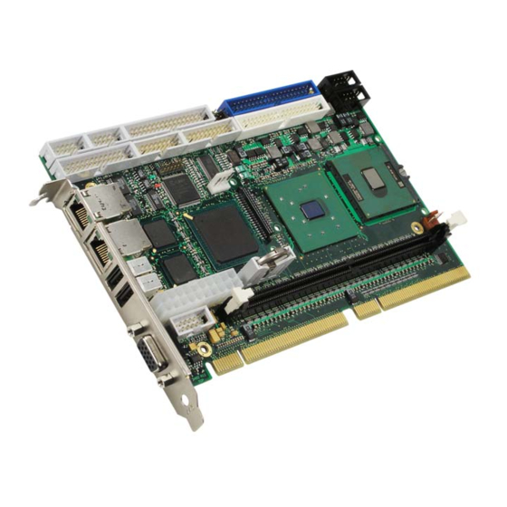
Page 19: Product Overview
The ePCI-101 is a highly integrated half-size PCI-board that provides the full functionality of a Pentium-M system. The ePCI-101 is the first half-size board to use the Pentium-M processor. This product is based on the ePCI-101 Pentium-M-Core from Kontron Embedded Computers Eching. The Pentium-M processor is a good solution for customers building test equipment, control room monitors, kiosks and other embedded applications that will use this board. -
Page 20: Board Specifications
COM1 as RS-232, COM2 configurable as RS-232/RS-422/485 Serial Two 10Base-T/100Base-Tx (Intel 82551ER) Ethernet Ultra DMA/100, support for four IDE drives (in master / slave configuration) Hard Disk Support for one drive Floppy Disk Supports CompactFlash disk module (on primary channel) Compact Flash ePCI-101 User’s Guide... - Page 21 12V, 5V, 3.3V, VBAT and Vcore voltage supervisor • Ethernet activity & link • Microsoft Windows 2000 family • OS Compatibility Microsoft Windows XP • Linux 198.12 x 129.92 x 19.05 mm / 7.8 x 4.8 x 0.75 inch Mechanical ePCI-101 User’s Guide...
-
Page 22: Epci Compliance
Ed.; CSA C22.2 No 60950-00; EN 60950:2000; IEC60950-1 • EMI/EMC: FCC 47 CFR Part 15, Class B; EN55022/EN55024 Warranty 2 year limited warranty * Designed to meet 1.4 ePCI Compliance This product conforms to the following specifications: • PICMG1.2 R1.0 • JILI R2.0 ePCI-101 User’s Guide... -
Page 23: Onboard Features
Intel ICH4 ............2-6 Super I/O ............2-11 Ethernet Controllers (J12 and J14) ....2-17 Video Interface ..........2-19 ATX Power Supply Control (J18)......2-20 Debugging Features ........2-21 System Management Features ......2-21 2.10 Miscellaneous Features ........2-22 ePCI-101 User’s Guide... -
Page 24: Block Diagram
2.1 Block Diagram ePCI-101 User’s Guide... -
Page 25: System Core
• Advanced Power Management features including Enhanced Intel SpeedStep® technology • Micro-FCPGA and Micro-FCBGA packaging technologies Please call Kontron to get the available CPU speed and configuration. See Intel’s Web site for additional details about Pentium M architecture and instruction set. - Page 26 25 MHz to 112 MHz (single channel/dual channel) -Supports data format of 18 bpp -SSC support of 0.5%, 1.0%, and 2.5% center and down spread with external SSC clock -LCD panel power sequencing compliant with SPWG timing specification ePCI-101 User’s Guide...
- Page 27 -Twelve level of detail MIP map sizes from 1x1 to 2k x 2k -Numerous texture formats including 32-bit RGBA -Alpha and Luminance maps -Texture chromakeying -Bilinear, trilinear, and anisotropic MIP map filtering -Cubic environment reflection mapping -Dot product bump-mapping -Embossed bump-mapping ePCI-101 User’s Guide...
- Page 28 -SMRAM space remapping to A0000h (128-kB) -Supports extended SMRAM space above 256-MB, additional 1-MB TSEG from top of memory, cacheable (cacheability controlled by CPU) -Supports Soft Off (S5) -ACPI 1.0b, 2.0 support -Enhanced Intel SpeedStep technology support ePCI-101 User’s Guide...
-
Page 29: Memory Interface
Signal Paths: Primary IDE interface: J4 (40-pin header) and J15 (CompactFlash connector) and Secondary IDE interface: J9 (40-pin header). Related Jumpers: JP7: when jumper is present, the CompactFlash is in “master” mode; otherwise it is in “slave” mode. ePCI-101 User’s Guide... -
Page 30: Compactflash Interface (J15)
34 D8 35 D1 36 D9 37 D2 38 D10 39 IOCS16# 40 GND Signal Paths: J15 (CompactFlash connector) Related Jumpers: JP7: when jumper is present, the CompactFlash is in “master” mode; otherwise it is in “slave” mode. ePCI-101 User’s Guide... -
Page 31: Usb Interfaces (J16 & J17)
Signal DATA- DATA+ Signal Paths: USB0 & USB1 signals are available on faceplate through J16 & J17 connector. Bios Settings: Advanced \ PCI configuration: Legacy USB Support (keyboard and mouse) ePCI-101 User’s Guide... -
Page 32: Usb2-3 And Usb4-5(J5 & J10)
J5 & J10 (USB header for two ports) Bios Settings: To enable/disable the USB Host controller, refer to Section Advanced Menu selection, USB control Sub-Menu. To support USB keyboard, refer to Section Advanced Menu selection, USB BIOS Legacy Support. ePCI-101 User’s Guide... -
Page 33: Audio Interface
LINE OUT R LINE OUT L AGND AGND LINE IN R LINE IN L AGND AGND MIC IN MIC BIAS Signal Paths: Signals are available through the J21 connector. BIOS Settings: Advanced Menu selection, PCI Configuration, AC97. 2-10 ePCI-101 User’s Guide... -
Page 34: Super I/O
31 GND 32 HDSEL# 33 N.C. 34 DSKCHG# Signal Paths: J3: Floppy disk interface on a standard header. Bios Settings: - Main - Select type of drive - Main Advanced \ On-Board Devices Configuration - Enable/disable floppy 2-11 ePCI-101 User’s Guide... -
Page 35: Multifunction Connector(J7)
Multifunction connector. Signal Signal KB:CLK KB:DATA SPEAKER MOUSE:CLK 11 MOUSE:DATA 13 PBRES# 15 IDE:ACT# Signal Paths: J7 (Multifunction Connector) Bios Settings: - Main - Specify disk type - Advanced \ PCI configuration - Enable/disable IDE adapter 2-12 ePCI-101 User’s Guide... -
Page 36: Serial Ports
This Serial Port is buffered for RS-232 operation. Signals include the complete signal set for handshaking, modem control, interrupt generation, and data transfer. Signal Paths: J2 Serial Port 1 (RS-232 Mode only) Bios Settings: Advanced \ On-Board Devices Configuration Serial port A Base I/O address Interrupt 2-13 ePCI-101 User’s Guide... - Page 37 When configured for RS-232 operation mode, the Serial Port 2 is 100% compatible with IBM-AT serial port signals. RS-422 Protocol The RS-422 protocol (Full Duplex) uses both RX and TX lines simultaneously during a communication session. 2-14 ePCI-101 User’s Guide...
-
Page 38: Parallel Port (J6)
IBM PC/XT, PC/AT, and PS/2 compatible bi-directional parallel port, Enhanced Parallel Port (EPP), and Enhanced Capabilities Port (ECP). Pin Signal Pin Signal ALF# STB# ERR# INIT# SLCTIN# 11 D4 13 D5 15 D6 17 D7 19 ACK# 21 BUSY 23 PE 25 SLCT 2-15 ePCI-101 User’s Guide... - Page 39 Note: For more information on the ECP protocol, please refer to the Extended Capabilities Port Protocol and ISA Interface Standard (available from Microsoft Corporation) or contact our Technical Support Department. 2-16 ePCI-101 User’s Guide...
-
Page 40: Ethernet Controllers (J12 And J14)
10Mbps and 100Mbps network speeds are automatically detected and switched. The 82551ER offers automatic crossover. When connecting an ePCI-101 to another computer, a straight cable can be used and the 82551ER will automatically swap the TX and RX pairs. - Page 41 Boot from LAN The Boot from LAN capability is supported. To enable the option, use the BIOS Setup program (Boot Menu Selection). Drivers A CD-ROM is included. It contains network drivers for most common operating systems. 2-18 ePCI-101 User’s Guide...
-
Page 42: Video Interface
Panel power sequencing and backlight control. • Dedicated CRT interface with data-interface control • Dual independent pipe for dual independent display • Dual Application/Dual View/Multi Display • Rotation support for 90, 180, 270 degree (LCD landscape/portrait rotation) 2-19 ePCI-101 User’s Guide... -
Page 43: Atx Power Supply Control (J18)
5VSB 20 VCC +12V Signal Paths: J18: ATX power connector for stand-alone use. J8: Hardware monitor connector to connect the pushbutton in stand-alone use. Bios Settings: • Power • Power button behaviour • After Power failure 2-20 ePCI-101 User’s Guide... -
Page 44: Debugging Features
The 8-bit content of I/O address 80h is serialized into a proprietary protocol and output on the J3 connector. In manufacturing, Kontron uses a display board to deserialize and display the postcode value on 7-segment LEDs modules. This approach enables you to see post codes before PCI initialization and avoid using a PCI postcode display board. -
Page 45: Programmable Watchdog
The ePCI-101 offers a way to access external SMBus device via CPLD register. Software Usage: • See register 0x193 in Appendix C for details. 2.10.2 Serial Number A DS2401 silicon serial number comes standard on the ePCI-101. The number can be read from register 0x193. (See Appendix C). 2-22 ePCI-101 User’s Guide... -
Page 46: Installing The Board
3. Installing the board Contents Setting Jumpers ..........3-1 Processor ............3-2 Memory ............3-2 Onboard Interconnectivity........3-4 Backup Battery..........3-6 ePCI-101 User’s Guide... -
Page 47: Setting Jumpers
Use these jumpers to connect or disconnect the termination resistors on/from Serial COM2 when set for RS-422/RS-485 operation mode 0. CompactFlash Setting Put the jumper in to configure Compact Flash in master mode. 3.1.2 Setting Jumper & Locations ePCI-101 User’s Guide... -
Page 48: Memory
This product ships with the CPU installed and a thermal solution. Because the thermal solution is a custom one and the thermal interface is critical for passive cooling, Kontron does not guarantee thermal performance if the heat sink is removed and then reinstalled by the end user. -
Page 49: Installing Memory
Push vertically the DIMM into the socket until the retaining clips on each side snap on. To remove a DIMM from a socket, push down the retaining clips on each side of the socket, to release the module. Pull the module upward to remove. ePCI-101 User’s Guide... -
Page 50: Onboard Interconnectivity
14-pin connector BIOS Mezzanine POST Code 4-pin locking Compact Flash 40-pin connector ATX Power Connector 20-pin connector CPU Fan 3-pin locking Audio Connector 10-pin connector Memory Socket DIMM 184-pin JILI 40-pin connector CMOS backup battery socket Battery ePCI-101 User’s Guide... -
Page 51: Front Plate Connectors And Indicators
3.4.2 Front Plate Connectors and Indicators Connector Description Comments Ethernet RJ-45 connectors with J12, J14 LAN0 and LAN1 built-in activity and link indicators J16, J17 USB0 and USB1 Standard 15-pin DSUB female Video Connector connector ePCI-101 User’s Guide... -
Page 52: Backup Battery
For preventive operational maintenance, verify the battery voltage after four years. After that, check the safety voltage more often. Battery life expectancy depends upon board use. • Kontron ordering MRP: 100-004 • Battery description: CR2032 3V battery ePCI-101 User’s Guide... -
Page 53: Software Setup
4. Software Setup Contents PHOENIX BIOS Setup Program ......4-1 Installing Drivers..........4-20 Console Redirection (VT100 Mode) ..... 4-21 ePCI-101 User’s Guide... -
Page 54: Phoenix Bios Setup Program
The system BIOS (Basic Input Output System) provides an interface between the operating system and the hardware of the ePCI-101 SHB. It uses the Phoenix Setup program, a setup utility in flash memory that is accessed by pressing the <DELETE> key at the appropriate time during system boot. - Page 55 The main menu of the Phoenix BIOS CMOS Setup Utility appears on the screen. KONTRON ePCI-101 BIOS Version 2.5 Main Advanced Power Boot Exit Main Item Specific Help System Time [13:30:00] <Tab>, <Shift-Tab>, System Date [01/01/2002] <Enter> selects field. Legacy Diskette [1.44/1.25 MB 3½"]...
-
Page 56: Menu Bar
<Enter>. A pointer ( ) marks all sub-menus. 4.1.2.2 Field Help Window The help window on the right side of each menu displays the help text for the selected field. It updates as you move the cursor to each field. ePCI-101 User’s Guide... - Page 57 <F9> loads factory installed Setup Default values. <F10> saves current settings and exists Setup. <Esc> or <Alt-X> exits Setup; in sub-menus, pressing these keys returns to the previous menu. <F1> or <Alt-H> displays General Help (this screen). [Continue] ePCI-101 User’s Guide...
- Page 58 Autotype the drive to select the optimum transfer mode. SMART Monitoring Display type of Monitoring. This field is a “Display Only”. This option can be changed in the Advanced Menu. ATAPI Removable Same choices as CD-ROM ePCI-101 User’s Guide...
- Page 59 If disabled, system always attempts to boot. System Displays amount of conventional Memory memory detected during boot up. Extended Displays the amount of RAM memory detected during boot up Memory minus the base memory (1 Mbyte). ePCI-101 User’s Guide...
- Page 60 This is a Sub-Menu. Additional setup menus to configure console. Redirection Turn system RAM off to free address space . Either a 128KB Enable Memory Disabled starting at 512KB or a 1MB extended memory gap starting at Enabled 15MB. ePCI-101 User’s Guide...
- Page 61 Normal will test all memory (1 MB at a time). Normal Extended Just zero it will zero the memory (faster). Just zero it Memory testing None None will just detect memory.(fastest) SMART Device Enabled Displays IDE failure prediction. Monitoring Disabled ePCI-101 User’s Guide...
-
Page 62: Pci Configuration
Enable or disable the on-board Ethernet controller 1. Ethernet 1 Disabled Controller Enabled Option Rom scan Initialize device expansion ROM. Disabled On-board Enabled Enable or disable the on-board Ethernet controller 2. Ethernet 2 Disabled Controller Enabled Option Rom scan Initialize device expansion ROM. Disabled ePCI-101 User’s Guide... - Page 63 Select the address to be used for the LCD in the case where the OS supports ACPI Video Extension. This option is under 0x110 IGD – ACPI LCD development. Do not modify if you do not have the appropriate Address 0x400 drivers. 4-10 ePCI-101 User’s Guide...
- Page 64 Set the mode for parallel port. Base I/O Select the base I/O address for parallel port. address IRQ 5 Interrupt Set the interrupt for parallel port. IRQ 7 Disabled Floppy disk Enabled Configure floppy disk controller. controller Auto 4-11 ePCI-101 User’s Guide...
- Page 65 Write Back Uncached Write Through Cache Base Controls caching of 512K-640K base memory. 512K-640K Write Protect Write Back Uncached Write Through Cache Extended Controls caching of system memory above 1MB. Memory Area Write Protect Write Back 4-12 ePCI-101 User’s Guide...
-
Page 66: Console Redirection
VT100 VT100, 8bit Console Type Enables the specified console type. PC ANSI, 7bit PC ANSI None Flow Control Enables Flow Control. XON/XOFF CTS/RTS Continue C.R. Off, On Enables Console Redirection after OS has loaded. after POST 4-13 ePCI-101 User’s Guide... - Page 67 Board Sensor 1 (Q58) Current Temperature CPU Die Temperature Current Temperature Board Sensor 2 (Q56) Current Temperature Fan CPU (RPM) Current Fan RPM Fan Tach. 1 (RPM) Current Fan RPM Fan Tach. 2 (RPM) Current Fan RPM 4-14 ePCI-101 User’s Guide...
- Page 68 Displays Status and limits. Vddr Display Status and limits. Vin 3.3V Vin 5V Vin 12V If a value is not present then a dashed line is displayed. Display a Status and limits. Vin –12V Vin –5V Vbat 4-15 ePCI-101 User’s Guide...
- Page 69 FACP table. (85 if enabled, 1001 if disabled) latency value Disabled Setting valid only for Windows 2000/XP. A fresh install of the OS Enabled APIC – IO APIC must occur when changing this setting. mode Disabled 4-16 ePCI-101 User’s Guide...
- Page 70 Write-protect the boot sector on the hard disk for virus Normal Fixed Disk boot protection. Requires a password to format or Fdisk the hard disk. sector Write Protect User Enable requires supervisor password to access floppy disk. Diskette Access Supervisor 4-17 ePCI-101 User’s Guide...
- Page 71 Phoenix QuietBoot displays a graphic illustration rather than the traditional POST messages while keeping you informed of diagnostic problems. Phoenix MultiBoot is a boot screen that displays a selection of boot devices from which you can boot your operating system. 4-18 ePCI-101 User’s Guide...
- Page 72 Setup, or you can choose a different device each time you boot during POST by selecting your boot device in The Boot First Menu (ESC key). Multiboot consist of: • Setup Boot Menu • Boot First Menu 4-19 ePCI-101 User’s Guide...
-
Page 73: Installing Drivers
4.2.3 Other Drivers For other operating system drivers and installation instructions or for more information, visit our Web site at www.kontron.com or our FTP site at ftp.kontron.ca/support/ or you also can contact Kontron’s Technical Support department. 4-20 ePCI-101 User’s Guide... -
Page 74: Console Redirection (Vt100 Mode)
Console Redirection is done by refreshing the video address @ B8000h at the selected baud rate. This means that a low baud rate refreshes the screen slowly, but the CPU time is maximized for the applications. A high baud rate refreshes the screen rapidly, but the display frequently interrupts the serial port. 4-21 ePCI-101 User’s Guide... -
Page 75: Running Without A Terminal
The board can boot up without a screen or terminal attached. If the speed is set to Auto and no terminal is connected, the speed is set to 115,200 bauds. You can run without a console by not enabling VT100 Mode and by disabling the onboard video. Partial Setup Full Setup Connector Connector 4-22 ePCI-101 User’s Guide... - Page 76 Appendix Contents Memory & I/O Maps ..........A.1 Interrupt Lines ............B.1 Kontron Extension Registers ........C.1 Board Diagrams ............D.1 Connector Pinouts............ E.1 BIOS Setup Error Codes ..........F.1 BIOS Update & Emergency Procedure ......G.1 Troubleshooting ............. H.1 Getting Help ............I.1...
-
Page 77: Memory & I/O Maps
CD800-DBFFF External SCSI BIOS 18KB-56KB , address may vary USB BIOS Legacy Support, 16K at DC000h if not disabled E0000-FFFFF System BIOS 100000-PCI Memory DRAM available PCI memory-4GB Hole for PCI memory, APIC and BIOS flash device ePCI-101 User’s Guide... - Page 78 Secondary IDE 278-27A Parallel Port (Option) 2F8-2FF Serial Port 2 (COM2 by default) 370-377 Floppy Disk (Option) 378-37A Parallel Port (LPT1) 3B0-3DF Video 3F0-3F7 Floppy Disk 3F8-3FF (COM1) Serial Port 1 (COM1 by default) 400-0FFF Chipset Reserved ePCI-101 User’s Guide...
-
Page 79: Interrupt Lines
Parallel Port IRQ 15 Secondary IDE * or available * :All functions marked with an asterisk (*) can be disabled or reconfigured. 1 Available lines service on board and external PCI/ISA PnP devices or a Legacy ISA device. ePCI-101 User’s Guide... -
Page 80: Kontron Extension Registers
C. Kontron Extension Registers FPGA/CPLD Registers Definition Unused (shaded) bits are reserved. It is strongly recommended not to modify unused bit to insure compatibility with other product. Base addresses are fixed. It can be changed but no option will be supported in the BIOS setup. - Page 81 For BIOS use only. When a firmware hub mezzanine is present, clearing this bit will give the onboard firmware hub address 0 (otherwise its 1 when the mezzanine is present). ClrHis# Clear and bring back to 1 to clear the reset history. ePCI-101 User’s Guide...
- Page 82 ExtFltEn When '1', enable generation of an interrupt when signal ExtFault# changes state. FanFltE Event on FanFault# signal (rising of falling edge). Clear on read. ExtFltE Event on ExtFault# signal (rising or falling edge). Clear on read. ePCI-101 User’s Guide...
-
Page 83: Board Diagrams
D. Board Diagrams Top Devices Surface Mount ePCI-101 User’s Guide... - Page 84 Bottom Devices Surface Mount ePCI-101 User’s Guide...
- Page 85 Mounting Holes ePCI-101 User’s Guide...
- Page 86 Top Mounting Components ePCI-101 User’s Guide...
-
Page 87: Connector Pinouts
Ethernet LAN 0 Connector POST Code Connector Ethernet LAN 1 Connector Compact Flash Connector USB 0 Connector USB 1 Connector ATX Power Connector CPU Fan Connector VGA Connector Audio Connector Memory Connector JILI Connector (on bottom) CMOS Battery Backup socket ePCI-101 User’s Guide... - Page 88 Serial Port 2 - (J1) RS-232/RS-422/RS-845 Signal Signal N.C. Floppy Drive (J3) Signal Signal DENSEL0# N.C. DENSEL1# INDEX# MTR0# DSEL1# DSEL0# MTR1# N.C. DIR# STEP# WDATA# WGATE# TRK0# WRPROT# N.C. RDATA# HDSEL# N.C. DSKCHG# # Active Low Signal ePCI-101 User’s Guide...
- Page 89 RST# IOW# IOR# IORDY GND/CSEL ACK# IOCS16# DIAG# CS0# CS1# DASP#/ACT# # Active Low Signal USB 2 & 3 and USB 4 & 5 (J5 & J10) Signal Signal USB2:VCC USB3:VCC USB2:DATA- USB3:DATA- USB2:DATA+ USB3:DATA+ USB2:GND USB3:GND ePCI-101 User’s Guide...
- Page 90 Parallel Port (J6) Standard Mode Signal Signal STB# ALF# ERR# INIT# SLCTIN# ACK# BUSY SELECT # Active Low Signal EPP Mode Signal Signal WRITE# DATASTB# N.C. N.C. ADDRSTRB# INTR WAIT# N.C. N.C. # Active Low Signal ePCI-101 User’s Guide...
- Page 91 Signal Signal KB:CLK KB:DATA SPEAKER MOUSE:CLK MOUSE:DATA PBRES# IDE:ACT# # Active Low Signal Hardware Monitor (J8) Signal Signal PWRBT# ICH_ALERT GPIO1/SMBDATA GPIO2/SMBCLK APFLT# CPUFLT# EXTFLT# FANFLT# CHASINT# FAN_TACH1 FAN_TACH2 FAN_TACH3 FAN_TACH4 FAN_TACH5 FAN_TACH6 # Active Low Signal ePCI-101 User’s Guide...
- Page 92 E.10 BIOS Mezzanine (J11) Signal Signal TEST# VCC3 FWH_MEZ AD[0] AD[1] AD[2] AD[3] FRAME# TBL# INIT# RESET# E.11 Lan 0 & Lan 1 (J12 & J14) Signal N.C. N.C. N.C. N.C. E.12 Post Code (J13) Signal +3.3V POST:DATA POST:CLOCK ePCI-101 User’s Guide...
- Page 93 E.13 CompactFlash™ (J15) Signal Signal CS1# ACK# CS0# IOR# PDIAG# IOW# RESET# CSEL ACT# IORDY IOCS16# # Active Low Signal E.14 USB0 and USB1 (located on faceplate) (J16 & J17) Signal DATA- DATA+ ePCI-101 User’s Guide...
- Page 94 Analog GND SDATA BLUE Analog GND HSYNC N.C. VCCE VSYNC SCLK E.18 Audio Connector (J21) Signal Signal LINE OUT R LINE OUT L AGND AGND LINE IN R LINE IN L AGND AGND MIC IN MIC BIAS ePCI-101 User’s Guide...
- Page 95 LVD2- (odd) LVD2+ (odd) LVC- (odd) LVC+ (odd) LVD3+ (odd) LVD3-(odd) DDC_Data LVD0- (even) LVD0+ (even) DDC_Clock LVD1- (even) LVD1+ (even) N.C. LVD2- (even) LVD2+ (even) LVDC- (even) LVDC+ (even) LVD3- (even) LVD3+ (even) EnableBacklight +12V +12V +12V ePCI-101 User’s Guide...
-
Page 96: Bios Setup Error Codes
Beeps POST Routine Description Verify Real Mode Disable Non-Maskable Interrupt (NMI) Get CPU type Initialize system hardware De-shadow BIOS code Initialize chipset with initial POST values Set IN-POST flag, Verify CMOS and RTC validity Initialize CPU registers ePCI-101 User’s Guide... - Page 97 Load alternate registers with CMOS values Initialize interrupt vectors POST device initialization 2- 1- 2- 3 Check ROM copyright notice Check video configuration against CMOS Initialize PCI bus and devices (I/O 81h = PCI Bus tested) Initialize all video adapters in system ePCI-101 User’s Guide...
- Page 98 Detect and install external RS232 ports Configure non-Motherboard Configurable Device IDE controllers Detect and install external parallel ports Initialize PC-compatible PnP ISA devices Re- initializes onboard I/O ports. Configure Motheboard Configurable Devices (optional) Initialize BIOS Data Area ePCI-101 User’s Guide...
- Page 99 Clear screen (optional) Display Summary Screen Try to boot with INT 19 Initialize POST Error Manager (PEM) Save the current boot type into CMOS Initialize error logging Check the requested boot type (Cold or Warm) Initialize error display function ePCI-101 User’s Guide...
- Page 100 Force Emergency Flash update check (Ctrl-E and bad CMOS) Test Gate A20 Extended checksum (optional) Install Console Redirection Interrupt Handler Extended BIOS data Fail BIOS stack initialization Unknown interrupt Setup WAD (reserved memory used by BIOS) Get CPU string Software SMI failure during POST ePCI-101 User’s Guide...
- Page 101 Output one beep before boot Boot to Mini DOS Clear Huge Segment Boot to Full DOS Test SIO Clock Validity Check TEST# Jumper for POST to COM, see Extension Registers. Reset System for Erratas, Hyper-Threading Early Boot Block Initialize completed. ePCI-101 User’s Guide...
- Page 102 Also, make sure that the disk is formatted as a boot device. Then reboot the system. EXPANSION ROM NOT INITIALIZED Cannot initialize the PCI expansion ROM. There is not enough free conventional memory for expansion ROM (C0000h to DFFFFh). Expansion ROM not required to boot should be disabled. ePCI-101 User’s Guide...
-
Page 103: Bios Update & Emergency Procedure
To create your own dongle, use a DB9 connector and follow the instruction below. Pin 4 (DTR) connected to Pin 8 (CTS) and Pin 9 (RI) Pin 7 (RTS) connected to Pin 6 (DSR) Pin 3 (Data Out) connected to Pin 2 (Data In) ePCI-101 User’s Guide... -
Page 104: Troubleshooting
H. Troubleshooting Power and Boot Problems This section describes common problems. Read it carefully before calling Kontron technical support. H.1.1 Power Supply Doesn’t Start A simple visual test for supply voltage is done by checking the fan operation. After the power is applied to the board, the power supply fan must be running. - Page 105 One or more supply is too low. power connector: +3.3V, +5V, +12V, +5Vsb. Those supplies should be within Make sure Pin #13 of multi-function connector (J8) is not Shorted reset switch. grounded. Unplug any cable on J8 to be sure. ePCI-101 User’s Guide...
- Page 106 First, you want to read the last postcode on a PCI post card or you want to listen to the beep post code. Consult the BIOS postcode listing. This might give you a clue on what the problem is. If you call Kontron technical support, the first thing they will ask you is to read the postcode. Possible Cause...
-
Page 107: Getting Help
I. Getting Help At Kontron, we take great pride in our customers’ successes. We believe in providing full support at all stages of your product development. If at any time you encounter difficulties with your application or with any of our products, or if you... - Page 108 • E-mail 1. Send us an e-mail at: RMA@ca.kontron.com. In the e-mail, you must include your name, your company name, your address, your city, your postal/zip code, your phone number, and your e-mail. You must also include the serial number of the defective product and a description of the problem.
- Page 109 _________________________ P.O. # Serial Number Failure or Problem Description (if not under warranty) Kontron Canada, Inc., 616 Curé Boivin, Boisbriand, Québec, Canada, J7G 2A7 Fax this form to Kontron’s Technical Support department in Canada at (450) 437-8053 ePCI-101 User’s Guide...
Need help?
Do you have a question about the ePCI-101 and is the answer not in the manual?
Questions and answers