Table of Contents
Advertisement
Quick Links
Advertisement
Table of Contents

Related Manuals for Kontron PCI-955 Board


Summary of Contents for Kontron PCI-955 Board
-
Page 2: Table Of Contents
Peripherals ......................51 Temperature Sensors ..................51 Real Time Clock....................51 Watchdog Timer....................51 Lithium Battery ....................52 Replacing the Lithium Battery ................. 52 Interrupt and I/O Maps ..................53 Interrupt Device Map ................... 53 PCI-955 Board - User’s Manual... - Page 3 South Bridge chipset Configuration ...............101 Exit ........................103 Save Changes and Exit .................103 Discard Changes and Exit ................103 Discard Changes ...................103 Load Optimal Defaults ...................104 Load Failsafe Defaults...................104 Technical Data....................105 Electrical Specifications ..................107 Mechanical Specifications..................107 Environmental Specifications ................107 PCI-955 Board - User’s Manual...
- Page 4 Contents CE Directives, Standards................... 108 Declaration of Conformity ................109 UL – Certificate of Compliance ..............110 Technical Support ................... 111 Returning Defective Merchandise..............112 PCI-955 Board - User’s Manual...
-
Page 5: Introduction
Kontron Embedded Computers is aware of such errors or inaccuracies or that Kontron Embedded Computers is unaware of these as a result of gross negligence and Kontron Embedded Computers has failed to eliminate these errors or inaccuracies for this reason. -
Page 6: Symbols Used In This Manual
Intel and Pentium are registered trademarks of Intel Corporation. ® AMI is a registered trademark of American Megatrends, Inc. Other product names cited in this manual may also be trademarks and are used here solely for identification purposes. PCI-955 Board - User’s Manual... -
Page 7: Important Instructions
In the event of damage to the device caused by failure to observe the hints in this manual and eventually on the device (especially the safety instructions), Kontron Embedded Computers shall not be required to honor the warranty even during the warranty period and shall be exempted from the statutory accident liability obligation. -
Page 8: Safety Instructions
The PCI-955 board must be used in accordance with the instructions for use. q The PCI-955 board is designed to be built into a system. The integration into the system has to be done such that the system complies with the IEC / EN 60950 safety rules. -
Page 9: Safety Instructions For The Lithium Battery
Safety Instructions q Repairs may only be carried out by a person authorized to do so by Kontron Embedded Computers. q It must be assumed that safe operation is no longer possible, · if the device has visible damage or ·... -
Page 10: Electrostatic Discharge (Esd)
Unpack or install this product only at EOS/ESD safe work stations. When safe work stations are not guaranteed, it is important for the user to be electrically discharged before touching the PCI-955 board with his/her hands or tools. This is most easily done by touching a metal part of your system housing. -
Page 11: Scope Of Delivery
CompactFlash-Adapter (T069) (has to be ordered separately) Labeling Information The PCI-955 board is labeled in the following way (refer to fig. 1 and 1a): q S/N (Serial Number) label, that includes the date of production and production tracking code q QM label that includes the Kontron assembly identification with quality mark. - Page 12 Scope of Delivery Fig. 1: Placement of Type, Serial Number, MAC Addresses and QM label S/N Label Type Label QM Label MAC Address Labels Fig. 1a: Detail with Type, Serial Number, MAC Addresses and QM label PCI-955 Board - User’s Manual...
-
Page 13: Board Description
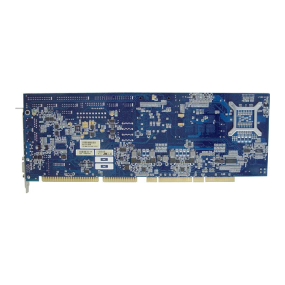
Board Description Board Description Fig. 2: PCI-955 Board Fig. 3: PCI-955 Board slot bracket with interfaces The PCI-955 is a multifunctional, full-size PICMG 1.0 Slot-CPU, designed for use in highly integrated platforms for a wide range of applications. The board supports an Intel® Pentium® M / Intel® Celeron M processor. - Page 14 LAN, DES, modem or capture card. Watchdog and power saving features are available. The implemented SuperI/O supports: 2x serial interfaces (COM1,2), 1xIrDA, 1x LPT interface, 1x PS/2 keyboard, 1x PS/2 mouse, 1x floppy interface. PCI-955 Board - User’s Manual...
-
Page 15: Features
1x IDE channel for up to two devices with Ultra ATA100/66/33 capabilities as Master and Slave. The IDE interface supports PIO IDE transfers up to 16 Mbytes/sec and Ultra ATA transfers up to100 Mbytes/sec. q Support for CompactFlash Drive (can be configured as Master or Slave) PCI-955 Board - User’s Manual... - Page 16 1x integrated on the MiniPCI slot connector q support of boot devices like: USB-FDD, USB-HDD, USB-CD, USB-Stick No wake-up capability is supported on the USB ports (the USB devices are not supplied with standby power). PCI-955 Board - User’s Manual...
- Page 17 The two Marvell Yukon 88E8053 Gigabit Ethernet controllers support 10/100/1000 Mbps data transfers and provide a standard IEEE 802.3, 802.3u, 802.3ab Ethernet interface for 10/100/1000 Base-TX applications. q Boot on LAN and Wake On LAN (WOL) are supported PCI-955 Board - User’s Manual...
-
Page 18: Extended Functions
Voltage Monitoring: +12V, +5V, +3.3V, 5VSB, VBAT, CPU core (8-bit resolution) FAN Speed Control: of two fans [J1 and J2, maximum current: 400 mA each] (8-bit resolution) Tachometer Outputs Monitoring: of three fans (J1, J2, J16) PCI-955 Board - User’s Manual... -
Page 19: Functional Diagram
CPU Fan Line-out 1x CD-IN 2x Serial Mic-in Chassis Fan1 1x IrDA Chassis Fan2 1x Floppy BIOS Flash On board connectors Legend: External interfaces Fig. 4: PCI-955/64 (with PCIe to PCI bridge) - Functional diagram PCI-955 Board - User’s Manual... - Page 20 CPU Fan Line-out 1x CD-IN 2x Serial Mic-in Chassis Fan1 1x IrDA Chassis Fan2 1x Floppy BIOS Flash On board connectors Legend: External interfaces Fig. 4a PCI-955/32 (only with PCI to ISA bridge) -Functional diagram PCI-955 Board - User’s Manual...
-
Page 21: Configurations
PCI-955 in order to set up a workable system. Memory Installation The PCI-955 board supports two 200-pin DDR2 SODIMM sockets for a total memory of up to 2GB DDR2 SDRAM. Single/double-sided memory modules can be combined in sizes of 256MB, 512MB up to a maximum 1GB pro DDR2 SODIMM socket. -
Page 22: Jumper And Connectors On The Pci-955
LVDS Connector (JILI) (40-pin) (page 47) 2x USB (USB2, USB3) (9-pin+key) (page 46) IDE0 (40-pin) (page 36) 2xUSB (USB4, USB5) (9-pin+key) (page 46) DVI-D Connector (page 48) Floppy Connector (34-pin) (page 39) The table is continued on the next page. PCI-955 Board - User’s Manual... - Page 23 MiniPCI Connector (126-pin) (page 40) DDR2 SODIMM0 Connector (200-pin) DDR2 SODIMM1 Connector (200-pin) IrDA Connector (6-pin) (page 49) 12V ATX Power Connector (4-pin) (page 32) ISA Connector FWH Upgrade Mezzanine Interface (reserved) XILINX (reserved) Lithium Battery Socket PCI-955 Board - User’s Manual...
-
Page 24: Jumper And Connector Locations
Configurations Jumper and Connector Locations Fig. 5: PCI-955 - Jumper and Connector Locations PCI-955 Board - User’s Manual... -
Page 25: Jumpers On The Pci-955
When connecting a CompactFlash on J8 (IDE port), make sure that you configure one device as master and the other as slave. Two master devices (or two slave devices) must not be installed on the IDE channel at the same time. PCI-955 Board - User’s Manual... - Page 26 The board might not start with this jumper in “closed” position. JP5:-pin Header; DIP 2-pin Setting Function Pin 1-2 Normal Operation Open (Default) Pin 1-2 Clear CMOS Short/Closed Content For clearing of content, please wait 10 sec. PCI-955 Board - User’s Manual...
- Page 27 RS422 with connected Short/Closed termination resistor Pin 1-2 RS422 without connected Open (Default) termination resistor Refer to BIOS settings for COM2 configuration as RS422 and RS485. Refer to COM2 on-board connector description for COM2 signals (RS232/RS422/485). PCI-955 Board - User’s Manual...
- Page 28 When set for RS485 mode in the BIOS, upon power-up or reset, the transceiver is set by default to receiver mode to prevent unwanted disturbance on the line. The operation mode for party lines requires termination resistors to be installed at both ends of the network. PCI-955 Board - User’s Manual...
- Page 29 Intel® Datasheet of the CPU before you attempt to install the processor. The jumper settings are necessary only if the PCI-955 board is delivered without CPU and you install an Intel® Pentium® M / Intel® Celeron® M CPU. For technical support, please contact...
- Page 30 1V5 and 1V8 CPU’s with a stepping code that includes “A#” operate only with 400 MHz or only with 533 MHz FSB. CPU’s with a stepping code that includes “B#” or higher support auto-detection of the FSB. PCI-955 Board - User’s Manual...
-
Page 31: External Interfaces
RJ45-sockets with integrated LEDs and support a data transfer rate of 10/100/1000Mbps. LAN1 and LAN2 PIN# RJ45 (female) Signal Name MDI0+ MDI0- MDI1+ MDI2+ MDI2- MDI1- MDI3+ MDI3- LINK / ACTIVE (green) 10/100 10/100/1000 (yellow) PCI-955 Board - User’s Manual... - Page 32 The PCI 955 board provides two external USB 2.0/1.1 interfaces. These con- nectors allow you to connect USB-compatible devices to the PCI-955 Slot-CPU. Pin Signal Name 4-pin USB Socket Type A Version 2.0/1.1 Data- Data+ PCI-955 Board - User’s Manual...
-
Page 33: On-Board Connectors
Signal Name +12V +12V J20: Main Power Connector This connector is the ATX main power connector and allows you to connect the ATX power supply cable to the PCI-955 board. Signal Name Pin # J20:-pin Header; DIP Pin # Signal Name 20-pin +3.3V... - Page 34 J12 is a 16-pin box header that provides following connections: Signal Name Pin # J12: Box Header, Pin # Signal Name (shrouded), DIP 16-pin KBCKL KBDATA VCC5V VCC5V Speaker VCC5V MCKL MDATA PBRES# HD_Active VCC5V Multifunctional PCI-955 Board - User’s Manual...
- Page 35 These pins can be used to connect the cable for an external PS/2 keyboard connector. Mouse:-pins 9, 10, 11, and 5 These pins can be used to connect the cable for an external PS/2 mouse connector. PCI-955 Board - User’s Manual...
- Page 36 J16: Chassis Fan2 Power Connector This is a 3-pin header that allows the connection of a chassis fan. The chassis fan must be a 12V fan (max. 750 mA). J16:-pin Header, 3-pin Pin # Signal Name Rotation +12V controlled PCI-955 Board - User’s Manual...
- Page 37 Data 3 Data 12 Data 2 Data 13 Data 1 Data 14 Data 0 Data 15 DREQ IOWR# IORD# IORDY P_ALE DACK# IOCS16# ADDR1 A[1] ATADET IDE0 ADDR0 A[0] ADDR2 2 A[2] CSO# Active LED# PCI-955 Board - User’s Manual...
- Page 38 Configurations J18, J24, J25, J26: SATA0, SATA1, SATA2 and SATA3 These connectors allow you to connect Serial-ATA devices. (Each of the SATA interfaces supports one Serial-ATA device). Serial ATA: Molex Pin # Signal Name SATA PCI-955 Board - User’s Manual...
- Page 39 Configurations J17: CompactFlash™ Adapter Connector The CompactFlash™ connector is located on the top side of the PCI-955 board. Signal Name Pin # Pin # Signal Name J17: CF Adapter CS3# CS1# DACK# IOR# DREQ IOW# ATA66DET VCC1 VCC3 VCC2 RESET#...
- Page 40 Signal Name (shrouded), DIP 34-pin Densel# Index Motor enable A Drive select B Drive select A Motor enable B Direction Step Pulse Write Data WGATE# Track 0 Write Protect Read Data Head Select Floppy Disk Change PCI-955 Board - User’s Manual...
- Page 41 VCC5V0 STOP# VCC3V3 GND_Audio INTA# VCC3V3 GND_Audio PERR# 122 MiniPCI_ACT# USBN DEVSEL# CBE1# VCC5V0 VCC3V3AUX VCC3V3AUX AD14 GND_Shield RST# AD15 GND_Shield VCC3V3 AD13 REQ# AD12 GNT# AD11 The table is continued on the next page. PCI-955 Board - User’s Manual...
- Page 42 Configurations VCC3V3 AD10 AD31 PME# AD29 CBE0# AD30 VCC3V3 AD27 VCC3V3 VCC3V3 AD25 AD28 AD26 CBE3# AD24 AD23 VCC5V0 IDISEL PCI-955 Board - User’s Manual...
- Page 43 DCD, Data carrier detect DSR, Data set ready Pins on the RXD, Receive data supplied cable connector: RTS, Request to send TXD, Transmit data CTS, Clear to send DTR, Data terminal ready COM1 RI, Ring indicator GND, ground PCI-955 Board - User’s Manual...
- Page 44 DCD, Data carrier detect supplied cable DSR, Data set ready connector: RXD, Receive data RTS, Request to send TXD, Transmit data CTS, Clear to send DTR, Data terminal ready COM2 RI, Ring indicator GND, ground PCI-955 Board - User’s Manual...
- Page 45 COM2: Box Header, D-SUB RS485 (shrouded), DIP 10-pin Connector (Pins on the on-board header) Pins on the Pin # Signal Name supplied cable connector: TRXD–, Transmit/Receive data TRXD+, TRXD– Transmit/Receive data TRXD+ COM2 GND, ground PCI-955 Board - User’s Manual...
- Page 46 (shrouded), DIP 26-pin Strobe# AutoFeed# PD0, Data 0 Error# PD1, Data 1 Initialize# PD2, Data 2 SLIN PD3, Data 3 PD4, Data 4 PD5, Data 5 PD6, Data 6 PD7, Data 7 Acknowledge# Busy Paper empty SLCT PCI-955 Board - User’s Manual...
- Page 47 (A slot bracket with 2x USB type A connectors can be ordered separately.) USB Port 4 USB Port 5 J9:-pin Header; DIP 10-pin Pin # Signal Name Pin # Signal Name VCC fused VCC fused PCI-955 Board - User’s Manual...
- Page 48 Signal Name ODD_LVD0- ODD_LVD0+ ENAVDD ODD_LVD1- ODD_LVD1+ Pin 40 ODD_LVD2- ODD_LVD2+ ODD_LVDC- ODD_LVDC+ JILI_DAT EVEN_LVD0- EVEN_LVD0+ JILI_CLK Pin 1 EVEN_LVD1- EVEN_LVD1+ LVDS (JILI) EVEN_LVD2- EVEN_LVD2+ EVEN_LVDC- EVEN_LVDC+ The table is continued on the next page. PCI-955 Board - User’s Manual...
- Page 49 Pin # Signal Name T.M.D.S Data 1+ T.M.D.S Data 2+ T.M.D.S Data 1- T.M.D.S Data 2- T.M.D.S CLK+ T.M.D.S Data 0+ T.M.D.S CLK– T.M.D.S Data 0- Power (fused) Hot Plug Detect DDC DATA DDC CLK PCI-955 Board - User’s Manual...
- Page 50 If wireless communication by IrDA is used, please set in BIOS, Serial Port 2 Mode to IrDA. Signal Name Pin # Pin Row: 6-pin Pin # Signal Name CIRRX# VCC5V0 5V (opt. 3.3V) IrTX IrRX PCI-955 Board - User’s Manual...
- Page 51 Pin # J22:Pin Header: 10-pin Pin # Signal Name LINEOUT_R LINEOUT_L AUDIO_GND AUDIO_GND LINEIN_R LINEIN_L AUDIO_GND AUDIO_GND MIC_IN MIC_BIAS J5: TV-out Connector J5: Right Angle Header; 4-pin Pin # Signal Name CVBS LUMA (Y) CHROMA (C) PCI-955 Board - User’s Manual...
-
Page 52: Peripherals
Watchdog Timer A watchdog timer is provided which forces either an IRQ, SMI, or Reset condition (configurable in the watchdog register). The watchdog time can be programmed ranging from 1 second up to 255 seconds. PCI-955 Board - User’s Manual... -
Page 53: Lithium Battery
(with a white line on the battery) in fig. 7! The lithium battery must be replaced with an identical battery or a battery type recommended by Kontron Embedded Computers (Lithium battery 3.0 V for RTC, type: CR2032). Do not dispose of lithium batteries in domestic waste. Dispose of the battery according to the local regulations dealing with the disposal of these special materials (e.g. -
Page 54: Interrupt And I/O Maps
PS/2 mouse port IRQ13 Math Coprocessor IRQ14 IDE Primary Disk Controller IRQ15 IDE Secondary Disk Controller IRQ16 PIRQA#, USB1.1A IRQ17 PIRQB#, AC’97 IRQ18 PIRQC#, USB1.1C IRQ19 PIRQD#, USB1.1B IRQ20 PIRQE#,LAN IRQ21 PIRQF# IRQ22 PIRQG# IRQ23 PIRQH#,USB2.0 PCI-955 Board - User’s Manual... -
Page 55: Memory Map
DMA is not supported on the ISA Bus !!!!! Troubleshooting BIOS Beep Codes If an irregular Post is received (your system does not boot and a continuously beep code is generated), please check your power supply and/or the main memory. PCI-955 Board - User’s Manual... -
Page 56: Ami Bios Configuration
AMI BIOS Configuration This chapter describes the settings available in the optional AMI-BIOS for the PCI-955 board. The AMI-BIOS (Basic Input/Output System) pre- installed in your computer system’s ROM supports Intel® Pentium® 4 and Celeron® processors in a standard IBM-AT compatible I/O system. -
Page 57: Navigation
This can lessen the probability of conflicting settings. The <F9> key on your keyboard is the Optimal-Default key. To set the Optimal-Default settings of the BIOS, press the <F9> key on your keyboard. PCI-955 Board - User’s Manual... -
Page 58: Main
HH:MM:SS (hours: minutes: seconds). Indicates the date of the device. If you change the date setting, System Date enter the date in the format MM.DD.YYYY (month/day/year). The “System Date” format can be arbitrarily configured. PCI-955 Board - User’s Manual... -
Page 59: Advanced
You can select the following sub menus of the Advanced BIOS Setup: · CPU Configuration · IDE Configuration · Floppy Configuration · SuperIO Configuration · Hardware Health Configuration · Event Log Configuration · MPS Configuration · Remote Access Configuration · USB Configuration PCI-955 Board - User’s Manual... -
Page 60: Cpu Configuration
AMI BIOS Configuration CPU Configuration Intel ® SpeedStep ™ tech. [Automatic] Settings: Maximum Speed, Minimum Speed, Automatic, Disabled PCI-955 Board - User’s Manual... -
Page 61: Ide Configuration
Allows you to configure up to 2 PATA & 2 SATA PATA Pri, SATA Sec SATA Pri, PATA Sec Allows you to configure up to 2 PATA & 2 SATA Allows you to configure up to 2 PATA PATA Only PCI-955 Board - User’s Manual... - Page 62 Set this value to use motherboard onboard IDE controller to Host detect the type of IDE cable present. Set this value to use IDE disk drive to detect the type of IDE Device cable present. PCI-955 Board - User’s Manual...
- Page 63 These entries are specific for each installed device as: · Primary IDE Master · Primary IDE Slave · Secondary IDE Master · Secondary IDE Slave The screens below are only an example of entries which could be available. PCI-955 Board - User’s Manual...
- Page 64 This setting allows the BIOS to auto-detect LBA mode control on the Auto specified channel (if the device supports it and the device is not already formatted with LBA Mode disabled). PCI-955 Board - User’s Manual...
- Page 65 This setting allows the BIOS to use the PIO mode 4. It has a data transfer rate of 16.6MBs. This setting generally works with all hard disk drives manufactured after 1999. For other disk drives, such as IDE CD-ROM drives, check the specifications of the drive. PCI-955 Board - User’s Manual...
- Page 66 If some read and write failures occur, check the length and quality of the integrated device cable first or set this option to a setting with a lower data transfer rate as specified for your device. PCI-955 Board - User’s Manual...
- Page 67 80-conductor ATA cable for this data transfer rate. UDMA6 If “UDMA6” is set the BIOS uses the Ultra DMA mode 6. It has a data transfer rate of 133.2MBs. You must use the 80-conductor ATA cable for this data transfer rate. PCI-955 Board - User’s Manual...
- Page 68 This option allows you to enable or disable the 32bit data transfer rate for IDE devices. If this option is “Enabled” the date transfer is accelerated and the CPU (PCI Bus) is relieved. Available settings are: Disabled and Enabled. PCI-955 Board - User’s Manual...
-
Page 69: Floppy Configuration
1.44 MB 3½“ floppy disk drive. This is the default setting for Floppy Drive A. 2.88 MB 3½“ Set this value if the floppy disk drive attached to the corresponding channel is a 2.88 MB 3½“ floppy disk drive. PCI-955 Board - User’s Manual... -
Page 70: Super Io Configuration
These fields allow you to select the onboard serial ports and their addresses. Available settings are: Available settings (without default setting) Default Serial Port 1 3F8/IRQ4 3E8/IRQ4 / 2E8/IRQ3 / Disabled Serial Port 2 2F8/IRQ3 3E8/IRQ4 / 2E8/IRQ3 / Disabled PCI-955 Board - User’s Manual... - Page 71 The COM2 port is used as an infrared port. IrDA If your “Serial Port 2 Mode” option is set to IrDA, there is a supplementary option available: selectable between: IR Duplex Mode [Half Duplex] and [Full Duplex] PCI-955 Board - User’s Manual...
- Page 72 This field selects the interrupt used for the parallel interface. It is possible to choose between: IRQ7 and IRQ5. This setting allows the parallel port to use the interrupt IRQ7. IRQ7 This setting allows the parallel port to use the interrupt IRQ5. IRQ5 PCI-955 Board - User’s Manual...
-
Page 73: Hardware Health Configuration
Hardware Health Event Monitoring These fields allow you to observe the parameters of the hardware monitoring function feature of the system. These values are read-only values for the monitoring of the system and show the PC health status. PCI-955 Board - User’s Manual... -
Page 74: Event Log Configuration
This selection enables the event log to log all PCI errors that occur. It is possible to choose between: Enabled and Disabled. This setting enables the PCI Error Logging function. Enabled This setting disables the PCI Error Logging function. Disabled PCI-955 Board - User’s Manual... -
Page 75: Mps Configuration
AMI BIOS Configuration MPS Configuration MPS Revision This setting allows you to configure the MPS ( M ulti P rocessor S ystem) Revision. Options for configuration: 1.1 and 1.4. PCI-955 Board - User’s Manual... -
Page 76: Remote Access Configuration
This option allows you to enable or disable the console redirection features. Available settings are: Enabled and Disabled. Serial port number This option allows you to select the serial port for console redirection. The available settings are: COM1 and COM2. PCI-955 Board - User’s Manual... - Page 77 This option allows you to enable or disable the VT-UTF8 Combo Key Support for ANSI/VT 100 terminals. The possible choices are: Enabled and Disabled. Client and target systems must have the same settings to enable communication. PCI-955 Board - User’s Manual...
- Page 78 AMI BIOS Configuration Sredir Memory Display Delay This option allows you to pause the memory display during redirection for the set value. Available settings are: No Delay, Delay 1 Sec, Delay 2 Sec and Delay 4 Sec. PCI-955 Board - User’s Manual...
-
Page 79: Usb Configuration
Support” option is set to Enabled or Auto and the option “USB 2.0 Controller” (SouthBridge Configuration) is set to “Enabled”. This option allows you to set the data signaling rate for the USB 2.0 controller. Possible settings are: FullSpeed and HiSpeed. PCI-955 Board - User’s Manual... - Page 80 This option specifies the amount of time the BIOS USB code should wait after iissuing a reset to the USB mass storage devices. The possible choices are: 10 Sec, 20 Sec, 30 Sec, and 40 Sec. PCI-955 Board - User’s Manual...
- Page 81 512 bytes). This option allows the device to be emulated as floppy drive. Floppy This option allows a hard disk image to be connected as a floppy Forced FDD image. PCI-955 Board - User’s Manual...
-
Page 82: Pcipnp
The operating system assumes part of the Plug&Play functions. This setting should only be selected if the operating system supports Plug&Play (e. g. Windows 95 or higher). The system BIOS assumes the recognition of the components and assigns the resources. PCI-955 Board - User’s Manual... - Page 83 This option allows you to specify the PCI expansion slot on the motherboard where the offboard PCI/ISA controller is installed. The available settings are: PCI Slot1, PCI Slot2, PCI Slot3, PCI Slot4, PCI Slot5, PCI Slot6, and Auto. PCI-955 Board - User’s Manual...
- Page 84 Available settings are: D0000, D4000, D8000 and DC000. For proper ISA card installation, set the same values of the BIOS options “Reserved Memory Size” and “Reserved Memory Address” as on the OS level and/or driver level (depending on the installed ISA card). PCI-955 Board - User’s Manual...
-
Page 85: Boot
AMI BIOS Configuration Boot In the Boot menu you define the sequence in which the system BIOS searches the drives for system files to start the operating system. PCI-955 Board - User’s Manual... - Page 86 This option allows or restricts the BIOS to perform all POST tests. It is possible to choose between: Enabled and Disabled. This setting allows the BIOS to skip certain POST tests to boot Enabled faster. This setting allows the BIOS to perform all POST tests. Disabled PCI-955 Board - User’s Manual...
- Page 87 It is possible to choose between: Force BIOS and Keep Current. This setting allows the computer system to force a third party Force BIOS BIOS to display its messages during system boot. Third party BIOS messages are not displayed during system Keep Current boot. PCI-955 Board - User’s Manual...
- Page 88 It is possible to choose between: Enabled and Disabled. The boot procedure is stopped whenever the BIOS detects an Enabled error. The system wait for an user input. The boot procedure will not be halted for any error that may be Disabled detected. PCI-955 Board - User’s Manual...
- Page 89 Set this value to allow option ROMs such as network controllers to trap BIOS interrupt 19. It is possible to choose between: Enabled and Disabled. The BIOS allows option ROMs to trap interrupt 19. Enabled The BIOS prevents option ROMs from trapping interrupt 19. Disabled PCI-955 Board - User’s Manual...
- Page 90 Boot Devices (examples) Description USB Floppy Device ((not supplied)) [USB: MITSUMI USB FD] [SATA: PM-HDS722580VLSA80] P rimary M aster device (internal SATA HDD) (not supplied) [Network: B4 D0 Yukon PXE] [Network: B5 D0 Yukon PXE] PCI-955 Board - User’s Manual...
- Page 91 AMI BIOS Configuration Ø Hard Disk Drivers List of hard drives available for use as the boot device ( possible selections depend on system configuration ). Available settings: SATA: PM-HDS722580VLSA80, HDD: SM-IC35L060AVVA07-0 and Disabled PCI-955 Board - User’s Manual...
- Page 92 1st Drive / ../ # Drive This option allows you to choose the removable drive used as the boot device ( possible selections depend on system configuration ). Available settings: MITSUMI USB FD and Disabled PCI-955 Board - User’s Manual...
-
Page 93: Security
If you select password support, you are prompted for a one to six character password. Type the password on the keyboard. The password does not appear on the screen when typed. Make sure you write it down. If you forget it, you must drain NVRAM and reconfigure. PCI-955 Board - User’s Manual... -
Page 94: Supervisor Password
NVRAM. If a Supervisor Password is installed two options are available: “User Access Level” with the following settings: Full Access, Limited, View Only, and No Access. “Password Check” with the following settings: Setup and Always. PCI-955 Board - User’s Manual... - Page 95 Select this option and press <Enter> to access the sub menu. You can use the sub menu to clear the user password. Select “Clear User Password” from the Security Setup menu and press <Enter>. “Clear User Password” ® [Ok] [Cancel] Choose your selection. PCI-955 Board - User’s Manual...
-
Page 96: Boot Sector Virus Protection
Before installing an operating system you have to change this selection to “Disabled”. During installation the first sector is written by the operating system. After the installation you can enable the boot virus protection by selecting “Enabled”. PCI-955 Board - User’s Manual... -
Page 97: Chipset
AMI BIOS Configuration Chipset All “Chipset” BIOS Setup options are described in this section. The “Chipset” BIOS Setup screen is shown below. PCI-955 Board - User’s Manual... -
Page 98: North Bridge Chipset Configuration
These settings allow you to select the graphics controller used as primary boot device. The available settings are: IGD, PEG/IGD, PEG/PCI, PCI/PEG and PCI/IGD. IGD : Integrated Graphics Display PEG : PCI Express Graphics PCI : PCI Device PCI-955 Board - User’s Manual... - Page 99 The option allows you to set the aperture size of the graphics. The aperture is a portion of the PCI memory address range dedicated for graphics memory address space. Host cycles that hit the aperture range are forwarded to the AGP without any translation. Available settings are: 128MB and 256MB. PCI-955 Board - User’s Manual...
- Page 100 Available settings are: Fixed Mode, DVMT Mode and Combo Mode. DVMT/Fixed Memory Available settings are: 64MB and 128MB. The option “DVMT/Fixed Memory” is not available when the option “DVMT Mode Select“ is set to Combo Mode. PCI-955 Board - User’s Manual...
- Page 101 1080i60, 1080p24, 1080p25, 1080p30, 1080p50 and 1080p60. TV Standard This option allows you to select the TV standard used as output. Available settings are: VBIOS-Default, NTSC, PAL, SECAM, SMPET240M, ITU-R television, SMPET295M, SMPET296M, EIA-770.2, and EIA770.3. PCI-955 Board - User’s Manual...
-
Page 102: South Bridge Chipset Configuration
This option allows you to enable or disable the EHCI USB controller function. Possible settings are: Enabled and Disabled. If this option “USB 2.0 Controller” is set to “Disabled”, the option “USB 2.0 Controller Mode ” (Advanced/USB Configuration) is not available. PCI-955 Board - User’s Manual... - Page 103 Restore on AC Power Loss This option allows you to specify the state the system should return to when power is restored after AC power loss. The available settings are: Power Off, Power On and Last State. PCI-955 Board - User’s Manual...
-
Page 104: Exit
Discard Changes and Exit This field exits BIOS Setup without saving the new settings. Discard Changes This field resets all values to those that were active when the computer was turned on without exiting BIOS Setup. PCI-955 Board - User’s Manual... -
Page 105: Load Optimal Defaults
These settings are not the optimised default settings (manufacturing defaults) for your system, but can be used if, after changes, the system does not run reliably. The Fail-Safe settings are designed for maximum stability, but not maximum performance. PCI-955 Board - User’s Manual... -
Page 106: Technical Data
ALC655 Audio Codec AMI BIOS PnP BIOS 1MB (8Mbits) Flash BIOS ROM (TSOP40) Watchdog Timer: programmable ca. 1sec. to 17 min. Watchdog TimeOut event: NMI or Reset The table is continued on the next page. PCI-955 Board - User’s Manual... - Page 107 1x Reset Button 1x Speaker 1x HDD/CF Activity LED Lithium battery 3.0 V for RTC, Type: CR2032 Power Supply External ATX 12V Information about the applicable operating systems Operating Systems refer to the website: www.kontron.com techsupport@kontron.com PCI-955 Board - User’s Manual...
-
Page 108: Electrical Specifications
Operating Altitude 10667.479 m (35,000 ft.) Storage Altitude 2.2G with CPU-heatsink, 15G without CPU-heatsink Vibration (operating) Mil-Std 810F Method 514.4 & 514.2 Mil-Std 810F Method 514.4 Procedure I (15G) Shock (operating) 30G, 5ms, half sine waveform PCI-955 Board - User’s Manual... -
Page 109: Ce Directives, Standards
U.S.A. UL 60950-1 :2003 / UR Marking Standards EN 55022:1998 + A1:2000 + A2 2003 (emission) EUROPE EN 55024:1998 + A1:2001 + A2 2003 (immunity) EN 61000-6-2:2001 U.S.A. FCC 47 CFR Part 15, Class A PCI-955 Board - User’s Manual... -
Page 110: Declaration Of Conformity
Declaration of Conformity Declaration of Conformity PCI-955 Board - User’s Manual... -
Page 111: Ul - Certificate Of Compliance
UL – Certificate of Compliance UL - Certificate of Compliance PCI-955 Board - User’s Manual... -
Page 112: Technical Support
Be ready to explain the nature of your problem to the service technician. If you have any questions about Kontron Embedded Computers or our products and services, you may reach us at the aforementioned numbers, or at : www.kontron.com... -
Page 113: Returning Defective Merchandise
Fax: (+49) 8165-77 412 E-mail: service@kontron.com 2. Make sure to receive an RMA number from Kontron Embedded Computers- Service before returning any merchandise. Clearly write or mark this number on the outside of the package you are returning. 3. Describe the device failure behavior as precisely as possible.
Need help?
Do you have a question about the PCI-955 Board and is the answer not in the manual?
Questions and answers