
Related Manuals for Kontron CP3010-SA


Summary of Contents for Kontron CP3010-SA
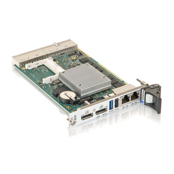
- Page 1 » User Guide « CP3010-SA Doc. ID: 1056-1693, Rev. 1.0 Date: November 4, 2014 The pulse of innovation...
-
Page 2: Revision History
Disclaimer Copyright © 2014 Kontron AG. All rights reserved. All data is for information purposes only and not guaranteed for legal purposes. Information has been carefully checked and is believed to be accurate; however, no responsibility is assumed for inaccuracies. Kontron and the Kontron logo and all other trademarks or registered trademarks are the property of their respective owners and are recognized. -
Page 3: Table Of Contents
User Guide CP3010-SA Contents Revision History ......................2 Imprint ........................2 Disclaimer ........................2 Contents ........................3 Tables ........................7 Figures ........................9 Warranty ........................10 Proprietary Note ......................10 Trademarks ......................10 Environmental Protection Statement ................10 Introduction ..................11 Board Overview .................. - Page 4 Operational Limits for the CP3010-SA .............. 52 CP3010-HDD Extension Module .............. 53 Overview....................53 Technical Specifications ................53 CP3010-HDD Module Functional Block Diagram ..........55 Front Panel of the CP3010-SA with CP3010-HDD Module........56 CP3010-HDD Module Board Layout ..............56 www.kontron.com...
- Page 5 Boot Setup Menu ..................73 9.2.5 Exit Setup Menu ..................73 The uEFI Shell .................... 74 9.3.1 Introduction, Basic Operation ............... 74 9.3.1.1 Entering the uEFI Shell ................74 9.3.1.2 Exiting the uEFI Shell .................. 74 9.3.2 Kontron-Specific uEFI Shell Commands ............75 www.kontron.com...
- Page 6 User Guide CP3010-SA uEFI Shell Scripting ..................76 9.4.1 Startup Scripting ..................76 9.4.2 Create a Startup Script ................. 76 9.4.3 Examples of Startup Scripts ................77 9.4.3.1 Execute Shell Script on Other Harddrive ............77 9.4.3.2 Enable Watchdog ..................77 9.4.3.3...
-
Page 7: Tables
CompactPCI Connector J1 Peripheral Slot Pinout ............31 CompactPCI Connector J2 Pinout (CP3010-SA Front I/O Vers.) ........32 Rear I/O CompactPCI Connector J2 Pinout (CP3010-SA Rear I/O Vers.) ......34 CompactPCI Rear I/O Connector J3 Signals ............... 34 GPIO Signal Description ..................35 COMA and COMB Signal Description ................ - Page 8 Main Setup Menu Sub-Screens and Functions ............70 Advanced Setup Menu Sub-Screens and Functions ............. 71 Security Setup Menu Functions ................72 TPM Configuration Sub-Screen ................72 Boot Priority Order ..................... 73 Exit Setup Menu Functions ................... 73 Kontron-Specific uEFI Shell Commands ..............75 www.kontron.com...
-
Page 9: Figures
CP3010-SA with Intel® Atom™ E3827, 1.75 GHz ............52 CP3010-HDD Module Functional Block Diagram ............55 Front Panel of the 8 HP CP3010-SA with CP3010-HDD Module ........56 CP3010-HDD Module Board Layout (Top View) ............56 Serial Port Connector J3 ..................57 CP-RIO3-04 4HP and 8HP Front Panels .............. -
Page 10: Warranty
Warranty This Kontron product is warranted against defects in material and workmanship for the warranty period from the date of shipment. During the warranty period, Kontron will at its discretion decide to repair or replace defective products. Within the warranty period, the repair of products is free of charge as long as warranty conditions are observed. -
Page 11: Introduction
Memory demanding applications can make use of up to 8 GB soldered DDR3L SDRAM memory running at 1333 MHz. For onboard data storage, the CP3010-SA offers a CFast option or a soldered SATA Flash and, on the 8HP extension module, an HDD/SSD option. On the system side, the CP3010-SA supports a PCI 32-bit, 33 MHz (66 MHz on request) CompactPCI®... -
Page 12: System Expansion Capabilities
1.2.1 CP3010-HDD Extension Module (8 HP) The CP3010-HDD extension module for the 8 HP CP3010-SA version provides onboard support for a 2.5” HDD/SSD and various ports on the front panel, such as one USB 2.0 port, one COM port, one Gigabit Ethernet, one CAN port, and two audio interfaces (Line-In and Line-Out). -
Page 13: Functional Block Diagram
User Guide CP3010-SA 1.3.1 Functional Block Diagram Figure 1: CP3010-SA Functional Block Diagram www.kontron.com... -
Page 14: Front Panel
1000BASE-T Ethernet Speed SPEED (green): 100BASE-TX Ethernet Speed SPEED (off) + ACT on: 10BASE-T Ethernet Speed SPEED SPEED Note: For information regarding the front panel of the 8 HP CP3010-SA with a CP3010-HDD ex- tension module, refer to Chapter 6. www.kontron.com... -
Page 15: Board Layout
User Guide CP3010-SA 1.3.3 Board Layout Figure 3: 4 HP CP3010-SA Board Layout (Top View) Logic Battery CFast (opt.) Intel® Atom™ (SoC) J10A SPD EEPROMs with DTS GbE A J10B GbE B DDR3L SDRAM Figure 4: 4 HP CP3010-SA Board Layout (Bottom View) -
Page 16: Technical Specification
It receives power from the backplane and supports rear I/O. CP3010-SA removal under power: When installed in a peripheral slot, the CP3010-SA suppor ts hot plugging on the power interface through a dedicated power controller, but not on the PCI inter- face. - Page 17 User Guide CP3010-SA Table 1: CP3010-SA Main Specifications (Continued) FEATURES SPECIFICATIONS DisplayPort Two DisplayPort interfaces (DVI/HDMI-capable through passive cable adapter) for connection to monitors Gigabit Ethernet Three 10 Base-T/100 Base-TX/1000 Base-T Gigabit Ethernet interfaces based on three Intel® I210-IT Ethernet controllers: »...
- Page 18 » Command shell for diagnostics and conf iguration » uEFI Shell commands executable from mass storage device in a pre-OS envi- ronment (open interface) Operating Systems There are var ious operating systems available for the CP3010-SA. For fur ther infor- mation, please contact Kontron. www.kontron.com...
- Page 19 3U, 4 HP, CompactPCI-compliant form factor Board Weight 4 HP CP3010-SA with heat sink (without CFast card): 243 grams Note: For information regarding the front panel of the 8 HP CP3010-SA with a CP3010-HDD ex- tension module, refer to Chapter 6. www.kontron.com...
-
Page 20: Standards
Note: Customers desiring to perform further environmental testing of the CP3010-SA must con- tact Kontron for assistance prior to performing any such testing. Boards without conformal coating must not be exposed to a change of temperature which can lead to condensation. -
Page 21: Related Publications
PRODUCT PUBLICATION CompactPCI Systems PICMG® 2.0, Rev. 3.0 CompactPCI® Specif ication CFast CFast Specif ication Revision 1.1 Platform Firmware Unif ied Extensible Firmware Interface (uEFI) specif ication, version 2.3.1 All Kontron products Product Safety and Implementation Guide, ID 1021-9142 www.kontron.com... -
Page 22: Functional Description
792 MHz Thermal Design Power 10 W For further information about the processors used on the CP3010-SA, please visit the Intel website. For further information concerning the suitability of other Intel processors for use with the CP3010-SA, please contact Kontron. -
Page 23: Memory
The CP3010-SA is provided with an UL-recognized CR2025, 3.0 V, “coin cell” lithium battery for the RTC. Power for the RTC may be provided either from the 4 HP / 8 HP CP3010-SA or from the backplane / rear transition module, i.e. only one battery may be used at a time in a system. When a battery is installed, refer to the operational specifications of the battery as this determines the storage temperature of the CP3010-SA. -
Page 24: Sata Flash
CP3010-SA 2.5.2 SATA Flash For flexible flash extension, the CP3010-SA provides either a CFast socket, J5, for a SATA 3Gb/s CFast memory card, or up to 64 GB soldered SLC-based NAND flash memory with built-in full hard disk emu- lation, up to 60 MB/s read rate, and up to 55 MB/s write rate. -
Page 25: General Purpose Leds
If the LED3..0 are lit red during boot-up, a failure is indicated. In this event, please contact Kontron for further assistance. The POST code is indicated during the boot-up phase. After boot-up, the LEDs indicate General Purpose or Port 80 signals, depending on the uEFI BIOS settings. -
Page 26: Usb Interfaces
Two USB 2.0 ports on the rear I/O, one of them switchable to the high-speed I/O extension connector, J7, for the CP3010-HDD extension module On the front panel, the CP3010-SA has one standard, type A, USB 3.0 connector, J8, and one standard, type A, USB 2.0 connector, J9. -
Page 27: Gigabit Ethernet
2.7.8 CompactPCI Inter face The CP3010-SA supports a flexible CompactPCI interface with a hot plug power interface (no PCI hot swap). In the system slot the PCI interface is in transparent mode, and in the peripheral slot the Com- pactPCI interface is isolated so that it cannot communicate with the CompactPCI bus. -
Page 28: Board Functionality When Installed In Peripheral Slot (Passive Mode)
» CP3010-SA rear I/O version Please ensure that the correct version is stated on the order. If the CP3010-SA is ordered with rear I/O configuration, various I/O interfaces and signals are available via the CompactPCI connector J2, such as USB, SATA, GbE, VGA, and COM, as well as power and management signals. If the CP3010-SA is or- dered with front I/O configuration, the I/O interfaces and signals mentioned above are isolated from the CompactPCI connector J2. -
Page 29: Enum# Interrupt
CompactPCI backplane connectors support guide lugs to en- sure a correct polarized mating (3.3 V or 5 V V(I/O) coding). The CP3010-SA supports universal (3.3 V and 5 V) PCI V(I/O) signaling voltages with one common termination resistor con- figuration. Therefore, the CP3010-SA can be inserted in both, 3.3 V and 5 V CompactPCI systems and provides itself no guide... -
Page 30: Compactpci Connectors J1 And J2 Pinouts
User Guide CP3010-SA 2.7.9.2 CompactPCI Connectors J1 and J2 Pinouts The CP3010-SA is provided with two 2 mm x 2 mm pitch female CompactPCI bus connectors, J1 and J2. Table 11: CompactPCI Connector J1 System Slot Pinout REQ64# ENUM# 3.3V... -
Page 31: Compactpci Connector J1 Peripheral Slot Pinout
A * indicates that the signal normally present at this pin is disconnected from the Com- pactPCI bus when the CP3010-SA is inserted in a peripheral slot. ** When the CP3010-SA is inserted in a peripheral slot, the function of the RST# signal can be enabled or disabled. -
Page 32: Compactpci Connector J2 Pinout (Cp3010-Sa Front I/O Vers.)
User Guide CP3010-SA Table 13: CompactPCI Connector J2 Pinout (CP3010-SA Front I/O Vers.) CLK6 CLK5 PRST# REQ6# GNT6# DEG# FAL# REQ5# GNT5# V(I/O) CLK4 GNT3# REQ4# GNT4# CLK2 CLK3 SYSEN# GNT2# REQ3# CLK1 REQ1# GNT1# REQ2# Note: The 64-bit CompactPCI signals are not used on the board and the 64-bit control and ad- dress signals are not terminated to V(I/O). -
Page 33: Optional Rear I/O Interface
Do not plug a rear I/O configured board in a backplane without rear I/O support. Failure to comply with the above will result in damage to your board. The CP3010-SA rear I/O provides the following interfaces (all signals are available on J2 only if the board is ordered with rear I/O functionality): »... -
Page 34: Rear I/O Compactpci Connector J2 Pinout (Cp3010-Sa Rear I/O Vers.)
User Guide CP3010-SA Table 14: Rear I/O CompactPCI Connector J2 Pinout (CP3010-SA Rear I/O Vers.) CLK6 USBA+ USBB+ USBA_PWR_5V CLK5 USBA- USBB- USBB_PWR_5V PWR_BTN# PWR_SLPS3# RIO_3.3V COMA_RXD COMA_DCD# COMA_DTR# GPI1/ COMA_CTS# COMB_CTS# COMA_TXD GPI0/ PRST# REQ6# GNT6# COMB_RXD COMA_DSR# COMA_RTS#... -
Page 35: Rear I/O Pin Description
1 = COMB Note: The default value is 1 if pin D4 is not connected (pull-up resistor to 3.3V on CP3010-SA). If the pin is connected, the default value depends on the rear I/O module. If the pin is driv- en by the rear I/O module, it must be considered that the CP3010-SA tolerates only 3.3 V... -
Page 36: Gpio Signal Description
VGA signals are available either on the front VGA connector, J6, or on the rear I/O interface due to the implemented switch on the CP3010-SA. Switching over from front to rear I/O or vice versa is effected using the uEFI BIOS. -
Page 37: Gigabit Ethernet Signal Description
Gigabit Ethernet signals are available either on the front RJ-45 connector or on the rear I/O interface due to the implemented switches on the CP3010-SA. Both Gigabit Ethernet channels are individually switchable to front or rear I/O. Switching over from front to rear I/O or vice versa is effected using the uEFI BIOS settings (default: front I/O). -
Page 38: Sata Signal Description
User Guide CP3010-SA SATA Interfaces The CP3010-SA provides two SATA interfaces on the rear I/O CompactPCI connector J2. Table 21: SATA Signal Description PIN on J2 SIGNAL FUNCTION DRIVEN BY SIGNALING VOLTAGE SATAARX+ Positive input por t A Rear I/O module... -
Page 39: Power Supply And Power Management Signal Description
User Guide CP3010-SA Power Supply and Power Management Signals The CP3010-SA provides the following power supply and power management signals to the rear I/O module. Table 23: Power Supply and Power Management Signal Description PIN on J2 SIGNAL FUNCTION DRIVEN BY... -
Page 40: Configuration
User Guide CP3010-SA 3 Conf iguration 3 .1 D I P S w i t ch C o n f i g u r a t i o n The DIP switch SW1 provides the following switches for board configuration: POST code indication, SPI boot flash selection, system write protection configuration and uEFI BIOS configuration. -
Page 41: System Write Protection
3 . 2 S y s te m Wr i te P ro t e c t i o n The CP3010-SA provides write protection for non-volatile memories via the DIP switch SW1, the uEFI Shell and a backplane pin. If one of these sources is enabled, the system is write protected. Please con- tact Kontron for further information before using these functions. -
Page 42: Write Protection Register (Wprot)
User Guide CP3010-SA 3.3.1 Wr ite Protection Register (WPROT) The Write Protection Register holds the write protect signals for non-volatile devices. Table 26: Write Protection Register (WPROT) ADDRESS 0x284 SFWP DSWP NAME Reserved BSWP SSWP ACCESS RESET BITFIELD DESCRIPTION System write protection status:... -
Page 43: Reset Status Register (Rstat)
User Guide CP3010-SA 3.3.2 Reset Status Register (RS TAT) The Reset Status Register is used to determine the host’s reset source. Table 27: Reset Status Register (RSTAT) ADDRESS 0x285 FPRS NAME PORS Reser ved CPRS WTRS ACCESS RESET 0000 BITFIELD... -
Page 44: Board Id High-Byte Register (Bidh)
CP3010-SA: 0xEF40 3.3.4 Geographic Addressing Register (GEOAD) The Geographic Addressing Register holds the CompactPCI geographic address (site number) used to assign the Intelligent Platform Management Bus (IPMB) address to the CP3010-SA. Table 29: Geographic Addressing Register (GEOAD) ADDRESS 0x28A NAME... -
Page 45: Watchdog Timer Control Register (Wtim)
User Guide CP3010-SA 3.3.5 Watchdog Timer Control Register (W TIM) Table 30: Watchdog Timer Control Register (WTIM) ADDRESS 0x28C WEN/WTR NAME ACCESS RESET 0000 BITFIELD DESCRIPTION Watchdog timer expired status bit: 0 = Watchdog timer has not expired 1 = Watchdog timer has expired. -
Page 46: Board Id Low-Byte Register (Bidl)
User Guide CP3010-SA 3.3.6 Board ID Low-Byte Register (BIDL) Table 31: Board ID Low-Byte Register (BIDL) ADDRESS 0x28D NAME BIDL ACCESS RESET 0x40 BITFIELD DESCRIPTION BIDL Board identif ication: CP3010-SA: 0xEF40 3.3.7 LED Conf iguration Register (LCFG) The LED Configuration Register holds a series of bits defining the onboard configuration for the front panel General Purpose LEDs. -
Page 47: Led Control Register (Lctrl)
User Guide CP3010-SA 3.3.8 LED Control Register (LCTRL) The LED Control Register enables the user to switch on and off the front panel General Purpose LEDs. Table 33: LED Control Register (LCTRL) ADDRESS 0x291 NAME LCMD LCOL ACCESS RESET 0000... -
Page 48: General Purpose Output Register (Gpout)
The General Purpose Output Register holds the general purpose output signals of the rear I/O Compact- PCI connector J2. This register can only be used if the CP3010-SA is ordered as a rear I/O version and the rear I/O GPIO operation is configured through the dedicated rear transition module configuration signal on the CompactPCI connector J2. -
Page 49: Power Considerations
4 .1 C P 3 010 - S A Vo l t a ge Ra n g e s The CP3010-SA has been designed for optimal power input and distribution. Still it is necessary to ob- serve certain criteria essential for application stability and reliability. -
Page 50: Cp3010-Sa Power Consumption
Typical 9.4 W 8.6 W Maximum 14.3 W 11.6 W The following table indicates the power consumption of the CP3010-SA accessories. Table 38: Power Consumption of CP3010-SA Accessories MODULE POWER CONSUMPTION SATA Flash module approx. 1.0 W Gigabit Ethernet (per interface) approx. -
Page 51: Thermal Considerations
An airflow of 2.0 m/s to 3.0 m/s is a typical value for a standard Kontron ASM rack. For other racks or housings the available airflow will differ. The maximum ambient operating temperature must be deter- mined for such environments. -
Page 52: Operational Limits For The Cp3010-Sa
5 .1 O p e r a t i o n a l L i m i t s fo r th e C P 3 010 - S A Figure 7: CP3010-SA with Intel® Atom™ E3845, 1.91 GHz Volumetric Flow Rate (CFM) -
Page 53: Cp3010-Hdd Extension Module
» Battery socket Note: If a CP3010-HDD module is used on the CP3010-SA, either the CP3010-SA or the CP3010- HDD module may be equipped with a battery. Using one battery on the CP3010-SA and one on the CP3010-HDD module simultaneously may result in premature discharge of the batteries. - Page 54 93% RH at 40°C, non-condensing (acc. to IEC 60068-2-78) Dimensions CP3010-HDD: 100 mm x 160 mm CP3010-SA with CP3010-HDD: 3U, 8 HP, CompactPCI-compliant form factor Board Weight CP3010-HDD: 150 grams (without HDD/SSD) 8HP CP3010-SA with CP3010-HDD: with heat sink (without HDD/SSD): 415 grams www.kontron.com...
-
Page 55: Cp3010-Hdd Module Functional Block Diagram
User Guide CP3010-SA 6 . 3 C P 3 010 - H D D M o d u l e Fu n c t i o n a l B l o ck D i a g r a m... -
Page 56: Front Panel Of The Cp3010-Sa With Cp3010-Hdd Module
6 . 4 Fro n t Pan e l o f th e C P 3 010 - S A w i th C P 3 010 - H D D M o d u l e Figure 10: Front Panel of the 8 HP CP3010-SA with CP3010-HDD Module CP3010 6 . -
Page 57: Module Interfaces (Front Panel And Onboard)
User Guide CP3010-SA 6 . 6 M o d u l e I n te r fa c e s ( Fro n t Pa n e l a n d O n b o a r d ) 6.6.1 C AN Inter face The CP3010-HDD provides a standard CAN interface implemented as one standard, 9-pin D-Sub connec- tor, J6. -
Page 58: Cp-Rio3-04 Rear Transition Module
The CP3010-SA provides optional rear I/O connectivity for peripherals. Some standard PC interfaces are implemented and assigned to the front panel and to the rear I/O connector J2 on the CP3010-SA. When the CP-RIO3-04 rear transition module is used, some signals of main board/front panel connec- tors are routed to the module interface. -
Page 59: Cp-Rio3-04 Front Panels
User Guide CP3010-SA 7.3 C P- R I O 3 - 0 4 Fro n t Pa n e l s Figure 13: CP-RIO3-04 4HP and 8HP Front Panels CP-RIO3-04 CP-RIO3-04 www.kontron.com... -
Page 60: Cp-Rio3-04 Rear Transition Module Layout
User Guide CP3010-SA 7.4 C P- R I O 3 - 0 4 Re a r Tr a n s i t i o n M o d u l e L ay o u t Figure 14: 4HP CP-RIO3-04 Rear Transition Module Layout... -
Page 61: 8Hp Cp-Rio3-04 Rear Transition Module Layout
User Guide CP3010-SA Figure 15: 8HP CP-RIO3-04 Rear Transition Module Layout ribbon Peripheral cable (COM1) Control CPCI COMA (COM1) Dual GbE ribbon cable (COM1) COMB (COM2) SATA www.kontron.com... -
Page 62: Module Interfaces
User Guide CP3010-SA 7.5 M o d u l e I n t e r f a c e s 7.5.1 USB Inter faces The CP-RIO3-04 rear transition module provides two standard, type A, USB 2.0 connectors, J11 and J12, on the front panel. -
Page 63: Peripheral Control Interface
User Guide CP3010-SA 7.5.5 Per ipheral Control Inter face A power supply with power management can be connected to the CP-RIO3-04 rear transition module via the peripheral control connector J13. The following table provides pinout information for the peripheral control connector J13. Refer to the module layout for connector and pin locations. -
Page 64: Rear I/O Interface On Compactpci Connector Rj2
User Guide CP3010-SA 7.5.7 Rear I/O Inter face on CompactPCI Connector rJ2 The CP-RIO3-04 rear transition module conducts a wide range of I/O signals through the rear I/O connector rJ2. Note: To support the rear I/O feature, a 3U CompactPCI backplane with rear I/O support is re- quired. -
Page 65: Rear I/O Compactpci Connector Rj2 Pinout
User Guide CP3010-SA Table 44: Rear I/O CompactPCI Connector rJ2 Pinout USBA+/bi USBB+/bi USBA_PWR_5V/ in GND USBA-/bi USBB-/bi USBB_PWR_5V/ in GND PWR_BTN#/out PWR_SLPS3#/in RIO_3.3V/in COMA_RXD/out COMA_DCD#/out COMA_DTR#/in COMB_CTS# /out COMA_CTS#/out COMA_TXD/in COMB_RXD/out COMA_DSR#/out COMA_RTS#/in COMA_RI#/out PWR_5VSTDBY/ out RSV IPA_DA+/bi IPA_DA-/bi... -
Page 66: Installation
8 . 3 B o a r d I n s t a l l a t i o n The CP3010-SA is designed for use either as a CompactPCI system controller or as an autonomous CPU board in a CompactPCI peripheral slot. -
Page 67: Standard Board Insertion
Failure to comply with the above may result in improper operation or damage to other sys- tem components, e.g. operating system failure, data loss, uncontrolled processing, etc. Note: In order to use the hot plug function of the CP3010-SA, a hot swap-capable backplane is required. 8.3.1 Standard Board Inser tion Prior to following the steps below, ensure that the safety requirements are met. -
Page 68: Cfast Card Installation
8 . 6 B a t te r y Re p l a c e m e n t The CP3010-SA RTC may be backed up using a single 3.0 V “coin cell” lithium battery from one of two possible points of installation: »... -
Page 69: Uefi Bios
The uEFI BIOS Boot Menu will appear. The CP3010-SA uEFI BIOS Setup program uses a hot key-based navigation system. A hot key legend bar is located on the bottom of the Setup screens. The following table provides information concerning the usage of these hot keys. -
Page 70: Setup Menus
User Guide CP3010-SA 9 . 2 S e t u p M e n u s The Setup utility features four menus listed in the selection bar at the top of the screen: » Main » Advanced » Security »... -
Page 71: Advanced Setup Menu
User Guide CP3010-SA 9.2.2 Advanced Setup Menu The Advanced Setup menu provides sub-screens and functions for advanced configuration. Note: Setting items on this screen to incorrect values may cause the system to malfunction. Table 48: Advanced Setup Menu Sub-Screens and Functions... -
Page 72: Security Setup Menu
CP3010-SA 9.2.3 Secur ity Setup Menu The Security Setup menu provides information about the passwords and functions for specifying the security settings. The passwords are case-sensitive. The CP3010-SA provides no factory-set passwords. Table 49: Security Setup Menu Functions FUNCTION DESCRIPTION Supervisor Password is: Read-only f ield. -
Page 73: Boot Setup Menu
User Guide CP3010-SA 9.2.4 Boot Setup Menu The Boot Setup menu lists the for boot device priority order, which is dynamically generated. Table 51: Boot Priority Order FUNCTION DESCRIPTION Boot Priority Order 1. Internal Shell Keys used to view or conf igure devices: <... -
Page 74: The Uefi Shell
9 . 3 T h e u E F I S h e ll The Kontron uEFI BIOS features a built-in and enhanced version of the uEFI Shell. For a detailed de- scription of the available standard shell scripting refer to the EFI Shell User’s Guide. For a detailed de- scription of the available standard shell commands, refer to the EFI Shell Command Manual. -
Page 75: Kontron-Specific Uefi Shell Commands
User Guide CP3010-SA 9.3.2 Kontron-Specif ic uEFI Shell Commands The Kontron uEFI implementation provides the following additional commands related to the specific HW features of the Kontron system. Table 53: Kontron-Specific uEFI Shell Commands COMMAND DESCRIPTION kBoardConf ig Conf igures non-volatile board settings, such as: »... -
Page 76: Uefi Shell Scripting
Conf igures the Kontron onboard Watchdog This command is used to enable the Kontron onboard Watchdog with reset target before OS boot. This can be used to detect if the OS fails to boot and react by reset. The uEFI Shell commands are not case-sensitive. Each uEFI Shell command is provided with a detailed online help that can be invoked by entering “<cmd>... -
Page 77: Examples Of Startup Scripts
User Guide CP3010-SA matted drive attached to the system. To copy the startup script to the flash, use the kBootScript uEFI Shell command. In case there is no mass storage device attached, the startup script can be generated in a RAM disk and stored in the SPI boot flash using the kRamdisk uEFI Shell command. -
Page 78: Handling The Startup Script In The Spi Boot Flash
User Guide CP3010-SA 9.4.3.3 Handling the Star tup Scr ipt in the SPI Boot Flash In case there is no mass storage device attached, the startup script can be generated in a RAM disk and stored in the SPI boot flash using the following instructions: Press <ESC>... -
Page 79: Firmware Update
9.5.1.1 uEFI BIOS Fail-Over Mechanism The CP3010-SA has two SPI boot flashes programmed with the uEFI BIOS, a standard SPI boot flash and a recovery SPI boot flash. The basic idea behind that is to always have at least one working uEFI BIOS flash available regardless if there have been any flashing errors or not. - Page 80 User Guide CP3010-SA CORPORATE OFFICES Europe, Middle East & Africa North America Asia Pacific Lise-Meitner-Str. 3-5 14118 Stowe Drive 17 Building,Block #1, ABP. 86156 Augsburg Poway, CA 92064-7147 188 Southern West 4th Ring Road Germany Beijing 100070, P.R.China Tel.: + 49 (0) 821 / 4086 0 Tel.: + 1 888 294 4558...
Need help?
Do you have a question about the CP3010-SA and is the answer not in the manual?
Questions and answers