Table of Contents
Advertisement
Quick Links
Advertisement
Table of Contents

Related Manuals for Kontron PCI-762


Summary of Contents for Kontron PCI-762
- Page 1 » User Guide « PCI-762 User’s Guide (Version 1.1) 1055-9117 www.kontron.com...
-
Page 2: Table Of Contents
9.3.8. DVI-D Pin Header (CN14) ....................... 22 9.3.9. Front Panel Connector (CN15) ......................23 9.3.10. PS/2 Keyboard, Mouse Connectors (CN17, CN18) ................24 9.3.11. External USB 3.0 Port Connectors (CN16, CN19) ................24 9.3.12. RS232/422/485 Pin Assignment (COM1) ..................25 www.kontron.com... - Page 3 14. PCI IRQ Routing ..........................61 14.1. PICMG PCI IRQ Routing ........................61 15. Configuring SATA for RAID ........................62 ® 15.1. Configuring SATA Hard Drive(s) for RAID Function (Controller: Intel Q77) ............. 62 16. iAMT Settings ............................ 73 16.1. Entering MEBx ..........................73 www.kontron.com...
- Page 4 1. Table of Contents PCI 762 – User’s Guide (Version 1.1) 16.2. Set & Change Password ........................74 ® 16.3. Intel iAMT Settings ........................... 76 16.4. iAMT Web Console ..........................80 17. Technical Support..........................82 17.1. Returning Defective Merchandise ......................82 www.kontron.com...
-
Page 5: Introduction
Kontron Embedded Computers. This manual is protected by copyright. All rights are reserved by Kontron Embedded Computers. Copies of all or part of this manual or translations into a different language may only be made with the prior written consent of Kontron Embedded Computers. -
Page 6: Symbols Used In This Manual
This symbol indicates that the product or parts thereof may be damaged if the corresponding warning notices are not observed. This symbol indicates general information about the product and the user manual. This symbol indicates detail information about the specific product configuration. This symbol precedes helpful hints and tips for daily use. www.kontron.com... -
Page 7: Safety Instructions
PCI 762 – User’s Guide (Version 1.1) 3. Safety Instructions 3.1. Safety Instructions for the Lithium Battery The PCI-762 board is equipped with a Lithium battery. For the replacing of this battery please observe the instructions described in the chapter 10.1 “Replacing the Lithium Battery”. Caution! Danger of explosion when replaced with wrong type of battery. -
Page 8: Important Instructions
Unpack or install this product only at EOS/ESD safe workstations. When safe work station are not guaranteed, it is important for the user to be electrically discharged before touching the PCI-762 board with his/her hands or tools. This is most easily done by touching a metal part of your system housing. -
Page 9: Scope Of Delivery
Serial Part cable Slot Bezel with 4x USB 2.0 5.1. Labeling Information Two types of printed labels on the PCI-762 board must show the following information: 1. Board identification label that has implemented: Board Designation/Serial Number/Part Number/Product Revision/QM-Field/Bar Code/Datamatrix Code 2. -
Page 10: Product Description
PCI 762 – User’s Guide (Version 1.1) 6. Product Description The PCI-762 PICMG 1.3 full-size Single Board Computer (SBC) supports LAG1155 socket H2 for Intel® Core™ i3 Desktop Processor, Intel® Core™ i5 Desktop Processor, Core™ i7 Desktop Processor with 32nm technology and Transfer Rate 1333/1600 MHz. -
Page 11: Features
2048x1536 pixels with 32-bit color at 75 Hz Analog Output Interface -- CRT from DAC output via 15-pin D-Sub connector on the edge; CRT always ON supported www.kontron.com... - Page 12 HD Audio Digital Header) Hardware Monitoring Monitoring temperatures, voltages, and cooling fan status Watchdog Timer Reset Supported (1-255 level) Dimensions 338mm x 126mm All specifications and images are subject to change without notice. www.kontron.com...
-
Page 13: Main Specifications
8. Main Specifications 8.1. Electrical Specifications Board Type of the external PSU Inputs via Version PCI-762 ATX PSU Backplane and +3.3 VSB, +5 VSB, PICMG 1.3 edge connector +3.3 V, +5.0 V, +12.0 V On-board 12 V ATX power connector: ATX2 +12V 8.2. -
Page 14: Mechanical Specifications
8. Main Specifications PCI 762 – User’s Guide (Version 1.1) 8.4. Mechanical Specifications Dimension PCI-762 338 mm x 126 mm Height x Width Weight 0.450 kg (0.992 lbs.) (without CPU fan) 8.4.1. Board Dimensions www.kontron.com... -
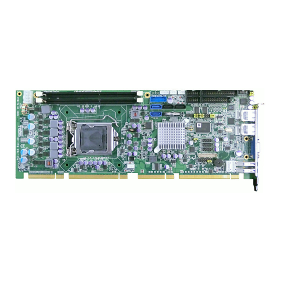
Page 15: Jumpers And Connectors
9. Jumpers and Connectors PCI 762 – User’s Guide (Version 1.1) 9. Jumpers and Connectors 9.1. Board Layout Lithium Battery www.kontron.com... -
Page 16: Jumper Settings
9. Jumpers and Connectors PCI 762 – User’s Guide (Version 1.1) 9.2. Jumper Settings Proper jumper settings configure the PCI-762 to meet your application purpose. Jumper Description Jumper Setting COM1 Mode Selection : RS-232 Short 3-5 , 4-6 COM1 Mode Selection : RS-232... -
Page 17: Audio Amplifier Jumper (Jp1)
If this jumper is enabled for AC power input, the system will be automatically power on without pressing soft power button. If this jumper is disabled for AC power input, it is necessary to manually press soft power button to power on the system. Description Function Jumper Setting Disable Auto Power-on Auto Power-on Jumper Selection Enable Auto Power-on (Default) www.kontron.com... -
Page 18: Connectors
CN16 Keyboard CN17 Mouse CN18 USB2.0/3.0 Port 0 CN19 SYS FAN FAN1 AUX FAN FAN2 CPU FAN FAN3 RJ45 (WG82579LM) LAN1 RJ45 (WG82574L) LAN2 Print Connecter PRINT1 SATA 0 6Gb(SATA3) SATA1 SATA 1 6Gb(SATA3) SATA2 SATA Port 2 SATA3 www.kontron.com... -
Page 19: Smbus Connector (Cn1)
SATA Port 4 (on edge connector) (no label) SATA Port 5 (on edge connector) (no label) COM1 Connector COM1 COM2 Connector COM2 Audio Connector AUDIO1 ATX Connecter ATX2 9.3.1. SMBUS Connector (CN1) Connector SMBUS CN1 is for SMBUS interface support. Signal CLOCK DATA www.kontron.com... -
Page 20: Floppy Disk Port Connector (Cn4)
Drive Density Select No connector No connector Index# Motor enable A# No connector Drive select A# No connector Direction# STEP# Write data# Write gate# Track 0 # Write protect# No connector Read data# Head selection# No connector Disk change# www.kontron.com... -
Page 21: Internal Usb Connectors (Cn5)
The 10-pin standard Universal Serial Bus (USB 2.0) connectors, CN8/10/13 on this board are for installing versatile USB interface peripherals. Signal Signal USB_PWR USB_PWR USB6- USB7- CN 13 USB6+ USB7+ The 5-pin standard Universal Serial Bus (USB) connectors, CN15, on this board are for installing versatile USB interface peripherals. www.kontron.com... -
Page 22: Lan2 Led Connectors (Cn6)
100, Low Active +3.3V 1000, Low Active 9.3.7. DB15 CRT Connector (CN11) Co-layout with CN12 CN11 is a DB15 connector commonly used for the CRT Monitor. Signal Signal Signal Green Blue DETECT DDC DATA Horizontal Sync Vertical Sync DDC CLK www.kontron.com... -
Page 23: Dvi-D Pin Header (Cn14)
9.3.8. DVI-D Pin Header (CN14) This board supports a 24-pin header (CN14) for DVI-D, via DVI-D cable. Signal Signal Signal Data2- Data2+ N.C. N.C. DDC CLK DDC Data N.C. Data1- Data1+ N.C. N.C. Data0- Data0+ N.C. N.C. Clock+ Clock- www.kontron.com... -
Page 24: Front Panel Connector (Cn15)
This connection is linked to hard drive activity LED on the control panel. LED flashes when HDD is being accessed. Pin 13 and 14 connect the hard disk drive to the front panel HDD LED, Pin 13 assigned as -, and Pin 14 as +. www.kontron.com... -
Page 25: Ps/2 Keyboard, Mouse Connectors (Cn17, Cn18)
The board provides the Keyboard (CN17) / Mouse (CN18) interface with a 5-pin connecter. Signal Clock DATA No connector 5VSBY 9.3.11. External USB 3.0 Port Connectors (CN16, CN19) The 9-pin standard Universal Serial Bus (USB 3.0) port connector on the board is for the installation of peripherals supporting the USB interface. www.kontron.com... -
Page 26: Rs232/422/485 Pin Assignment (Com1)
Receive Data (RXD) DATA+ Request to Send (RTS) No connector No connector Transmit Data (TXD) No connector Clear to Send (CTS) No connector No connector Data Terminal Ready (DTR) No connector Ring Indicator (RI) No connector No connector Ground (GND) Disconnect(NI) www.kontron.com... -
Page 27: Com Port Rs-232 Pin Assignment (Com2)
Receive Data (RXD) Request to Send (RTS) Transmit Data (TXD) Clear to Send (CTS) Data Terminal Ready (DTR) Ring Indicator (RI) Ground (GND) Disconnect(NI) ® 9.3.14. Intel HD Audio Digital Header (AUDIO1) Signal Signal MIC IN LINE_IN_L LINE_IN_R LINE_OUT_L LINE_OUT_R www.kontron.com... -
Page 28: Atx 8 Pin 12V In Connector (Atx2)
The CPU fan connector FAN3 provides power to the CPU fan. Signal Ground +12V Rotation Detection Speed Control 9.3.17. System & Auxiliary Fan Connectors (FAN1, FAN2) You can connect the system cooling fan cable to FAN1/FAN2 for system cooling fan power. Signal +12V Rotation Detection www.kontron.com... -
Page 29: Ethernet Rj-45 Connectors (Lan1, Lan2)
LAN1 and connect the other end (phone jack) to a 100-Base-T hub or 1000-Base-T hub. Signal Tx+ (Data transmission positive) Tx- (Data transmission negative) Rx+(Data reception positive) RJ-1(For 1000 base T-Only) RJ-1(For 1000 base T-Only) Rx- (Data reception negative) RJ-1(For 1000 base T-Only) RJ-1(For 1000 base T-Only) Active LED Speed LED www.kontron.com... -
Page 30: Parallel Port Connector (Print1) Print Port Connector
Microsoft and Hewlett Packard extended capabilities port (ECP) is IEEE 1284 compliant. Signal Signal Strobe# Auto Form Feed# Data 0 Error# Data 1 Initialize# Data 2 Printer Select In# Data 3 Data 4 Data 5 Data 6 Data 7 Acknowledge# Busy Paper Empty# Printer Select www.kontron.com... -
Page 31: Sata Connectors (Sata1[3.0], Sata2[3.0], Sata3, Sata4)
9. Jumpers and Connectors PCI 762 – User’s Guide (Version 1.1) 9.3.20. SATA Connectors (SATA1[3.0], SATA2[3.0], SATA3, SATA4) These SATA connectors are for high-speed SATA interface ports and they can be connected to hard disk devices. Signal SATA_TX+ SATA_TX- SATA_RX- SATA_RX+ www.kontron.com... -
Page 32: Lithium Battery
PCI 762 – User’s Guide (Version 1.1) 10. Lithium Battery PCI-762 is provided with a 3.0 V “coin cell” lithium battery for the RTC operation and CMOS Setup RAM. Please observe the chapter 3.1 “Safety Instructions for the Lithium Battery”. -
Page 33: Hardware Description
The PCI-762 Series uses AMI Plug and Play BIOS with a single 32Mbit SPI Flash. 11.3. System Memory The PCI-762 supports four 240-pin DDR3 DIMM sockets for a maximum memory of 8GB DDR3 SDRAMs. The memory module can come in sizes of 1GB, 2GB and 4GB. -
Page 34: Hardware Installation
2. Rotate load lever to open position at approximately 135°. 3. Rotate load plate to open position at approximately 150°. Apply pressure to corner with right-hand thumb when opening or closing load lever - otherwise lever will bounce back (as a mouse trap) causing bent contacts. www.kontron.com... - Page 35 3. Lift protective cover away from the socket, being careful not to touch the electrical contacts. Vertical removal is NOT recommended, as it requires higher force and can lead to socket contact damage. Never Touch Fragile Socket Contacts to Avoid Damage and DO NOT TOUCH PROCESSOR SENSITIVE CONTACTS AT ANY TIME DURING INSTALLATION. www.kontron.com...
- Page 36 Notches.) The socket will have cutouts for your fingers to fit into (see image below). 5. Carefully place the processor into the socket body vertically (see image below). Tilting or roughly shifting it into place can damage socket contacts. Do not use a vacuum pen for installation. www.kontron.com...
- Page 37 11. Hardware Description PCI 762 – User’s Guide (Version 1.1) 6. Verify that package is within the socket body and properly connected to orientation keys. www.kontron.com...
- Page 38 Step 4: Fan heatsink handling 1. Orientate the CPU cooling fan to fixing holes on the board. 2. Screw the CPU cooling fan onto the board. 3. Make sure the CPU fan is plugged to the CPU fan connector. www.kontron.com...
-
Page 39: Installing The Memory
3. Install the memory module into the socket and push it firmly down until it is fully seated. The socket latches are levered upwards and clipped on to the edges of the DIMM. 4. Install any remaining DIMM modules. www.kontron.com... -
Page 40: Ami Bios Utility
<Esc> key to exit the setup without saving your changes. The <Enter> key allows you to display or change the setup option listed for Enter a particular setup item. The <Enter> key can also allow you to display the setup sub- screens. www.kontron.com... -
Page 41: Main Menu
Use this options to change the system date and time. Highlight System Date or System Time using the <Arrow> keys. Enter new values through the keyboard. Press the <Tab> key or the <Enter> keys to move between fields. The date must be entered in MM/DD/YY format. The time is entered in HH:MM:SS format. www.kontron.com... -
Page 42: Advanced Menu
(refer to picture below). For items marked with “”, please press <Enter> for more options. Important Setting incorrect field values may cause the system to malfunction. www.kontron.com... -
Page 43: Acpi Settings
ACPI Sleep State Allows you to select the Advanced Configuration and Power Interface (ACPI) state to be used for system suspend. Here are the options for your selection, S1 (CPU Stop Clock), S3 (Suspend to RAM) and Suspend Disable. www.kontron.com... -
Page 44: Trusted Computing
PCI 762 – User’s Guide (Version 1.1) 12.4.2. Trusted Computing You can use this screen to select options for the Trusted Computing, and change the value of the selected option. A description of the selected item appears on the right side of the screen. www.kontron.com... -
Page 45: Cpu Configuration
This screen shows the CPU Configuration, and you can change the value of the selected option. Hyper-threading This item can set enable or disable for support Hyper-threading Technology. Intel Virtualization Technology Allows a hardware platform to run multiple operating systems separately and simultaneously, enabling one system to virtually function as several systems. www.kontron.com... -
Page 46: Sata Configuration
SATA Mode Use this item to choose the SATA operation mode. Here are the options for your selection, IDE Mode, AHCI Mode and RAID Mode. www.kontron.com... -
Page 47: Pch-Fw Configuration
12. AMI BIOS Utility PCI 762 – User’s Guide (Version 1.1) 12.4.5. PCH-FW Configuration This screen displays information about the ME firmware. www.kontron.com... -
Page 48: Amt Configuration
INTEL AMT You can enable this item to support AMT (active management technology) function to follow up the procedure for the access to AMI program screen. Disable ME Use this item to unconfigure the ME settings. www.kontron.com... -
Page 49: Usb Configuration
PCI 762 – User’s Guide (Version 1.1) 12.4.7. USB Configuration You can use this screen to select options for the USB Configuration, and change the value of the selected option. A description of the selected item appears on the right side of the screen. www.kontron.com... -
Page 50: Super Io Configuration
This option specifies the base I/O port address and Interrupt Request address of serial port 1. The Optimal setting is 3F8/IRQ4. Parallel Port Configuration This item allows you to determine the Parallel Port Mode and I/O address for onboard parallel port. www.kontron.com... -
Page 51: H/W Monitor
This item can adjust the CPU/System/Auxiliary Fan speed automatically in accordance with the current CPU/System temperature that can prevent the system overheating. The Auxiliary Fan also in accordance with current CPU temperature. There are these options Manual Mode and Thermal Cruise Mode. www.kontron.com... -
Page 52: Intel Rc Drivers Version Detail
12. AMI BIOS Utility PCI 762 – User’s Guide (Version 1.1) 12.4.10. Intel RC Drivers Version Detail This screen shows the version numbers of the Intel RC drivers. www.kontron.com... -
Page 53: Chipset Menu
The Chipset menu allows users to change the advanced chipset settings. You can select any of the items in the left frame of the screen to go to the sub menus: PCH-IO Configuration System Agent (SA) Configuration For items marked with “”, please press <Enter> for more options. www.kontron.com... -
Page 54: Pch-Io Configuration
12. AMI BIOS Utility PCI 762 – User’s Guide (Version 1.1) 12.5.1. PCH-IO Configuration This screen shows the PCH Azalia Audio Interface Configuration, and a description of the selected item appears on the right side of the screen. www.kontron.com... -
Page 55: System Agent (Sa) Configuration
12. AMI BIOS Utility PCI 762 – User’s Guide (Version 1.1) 12.5.2. System Agent (SA) Configuration It is strongly recommended that you do not modify these options unless you are an advanced user. www.kontron.com... -
Page 56: Boot Menu
Quiet Boot Use this item to enable or disable the Quite Boot state. The default setting is disabling. Bootup NumLock State Use this item to select the power-on state for the NumLock. The default setting is on. www.kontron.com... -
Page 57: Security Menu
This item indicates whether an administrator password has been set. If the password has been installed, Installed displays. If not, Not Installed displays. User Password This item indicates whether a user password has been set. If the password has been installed, Installed displays. If not, Not Installed displays. www.kontron.com... -
Page 58: Save & Exit Menu
Changes from the Save & Exit menu and press <Enter>. Select Yes to save changes. Discard Changes Select this option to quit Setup without making any permanent changes to the system configuration. Select Discard Changes from the Save & Exit menu and press <Enter>. Select Yes to discard changes. www.kontron.com... - Page 59 Optimal settings are designed for maximum system performance, but may not work best for all computer applications. In particular, do not use the Optimal Setup options if your computer is experiencing system configuration problems. Select Restore Defaults from the save & Exit menu and press <Enter>. www.kontron.com...
-
Page 60: Watchdog Timer
Activate WDT :O 2E 30 O 2F 01 Set Second or Minute O 2E F5 O 2F N N=00 or 08(See below table) ↓ Set base timer :O 2E F6 O 2F M=00, 01, 02 FF(Hex) ,Value=0 to 255 ↓ www.kontron.com... - Page 61 03h: Time-out occurs after 3 second ………………………........FFh: Time-out occurs after 255 second N=08 M= 00h: Time-out Disable 01h: Time-out occurs after 1 minute 02h: Time-out occurs after 2 minutes 03h: Time-out occurs after 3 minutes FFh: Time-out occurs after 255 minutes www.kontron.com...
-
Page 62: Pci Irq Routing
14. PCI IRQ Routing PCI 762 – User’s Guide (Version 1.1) 14. PCI IRQ Routing 14.1. PICMG PCI IRQ Routing Device Slot PCI Slot 0 BCDA PCI Slot 1 CDAB PCI Slot 2 DABC PCI Slot 3 ABCD www.kontron.com... -
Page 63: Configuring Sata For Raid
(2) Configuring SATA controller mode and boot sequence by the BIOS Setup You have to make sure whether the SATA controller is configured correctly by system BIOS Setup and set up BIOS boot sequence for the SATA hard drive(s). www.kontron.com... - Page 64 Turn on your system, and then press the Del button to enter BIOS Setup during running POST (Power-On Self Test). If you want to create RAID, just go to the Advanced Settings menu/IDE configuration, select the Configure SATA#1 as, and press <Enter> for more options. (2)-1-2 A list of options appears, please select RAID. www.kontron.com...
- Page 65 15. Configuring SATA for RAID PCI 762 – User’s Guide (Version 1.1) (2)-2 Set CDROM for First Boot Device under the Boot Settings menu to boot CD-ROM after system restarts. (2)-3 Save and exit the BIOS Setup. www.kontron.com...
- Page 66 Configuration Utility" shows up, accordingly, press <CTRL+ I> to enter the RAID BIOS setup utility. (3)-2 After you press <CTRL+ I>, the Create RAID Volume screen will appear. If you want to create a RAID array, select the Create RAID Volume option in the Main Menu and press ENTER. www.kontron.com...
- Page 67 After entering the CREATE VOLUME MENU screen, you can type the disk array name with 1~16 letters (letters cannot be special characters) in the item “Name”. (3)-3-2 When finished, press ENTER to select a RAID level. There are three RAID levels, RAID0, RAID1 and RAID5 & RAID10. Select a RAID level and press ENTER. www.kontron.com...
- Page 68 Set the stripe block size. The KB is the standard unit of stripe block size. The stripe block size can be 4KB to 128KB. After the setting, press ENTER for the array capacity. (3)-5 After setting all the items on the menu, select Create Volume and press ENTER to start creating the RAID array. www.kontron.com...
- Page 69 When prompting the confirmation, press “Y“ to create this volume, or “N“ to cancel the creation. After the creation is completed, you can see detailed information about the RAID Array in the DISK/VOLUME INFORMATION section, including RAID mode, disk block size, disk name, and disk capacity, etc. www.kontron.com...
- Page 70 If you want to delete a RAID volume, select the Delete RAID Volume option in Main Menu. Press ENTER and follow on- screen instructions. Please press [ESC] to exit the RAID BIOS utility. Now, you can proceed to install a SATA driver controller and the operating system. www.kontron.com...
- Page 71 Users can insert the Driver CD and the formatted blank floppy disk in another system. And then, please copy all of file of the f6flpy32 folder in the Driver CD to a floppy disk. Please copy all of file of the f6flpy64 folder, if installing 64-bit Windows Operating System. www.kontron.com...
- Page 72 "Press F6 if you need to install a 3rd party SCSI or RAID driver". After pressing the F6 button, there will be a few moments for some files being loaded before next screen appears. (5)-2 When you see the screen below, insert the floppy disk containing the SATA driver and press “S”. www.kontron.com...
- Page 73 If a message on the screen saying that one or some file(s) cannot be found, please check the floppy disk or copy the correct SATA driver again from the driver CD. If you are installing AHCI, Please select”Intel® 7 Series/C216 Chipset Family SATA AHCI Controller www.kontron.com...
-
Page 74: Iamt Settings
16.1. Entering MEBx 1. You must go to BIOS TO start iAMT function. 2. Exit from BIOS after starting iAMT, and press Ctrl+P to enter MEBx Setting. It is better to press Ctrl+P before the screen popping out. www.kontron.com... -
Page 75: Set & Change Password
PCI 762 – User’s Guide (Version 1.1) 16.2. Set & Change Password 1. You will be asked to set a password when first log in. The default password is ‘admin’. 2. You will be asked to change the password before setting ME. www.kontron.com... - Page 76 One lower case • One number • One special symbol, such as ! 、 $ or ; , • (、 " , excepted) Underline ( _ ) and space are valid characters for password, but they won’t make higher complexity. www.kontron.com...
-
Page 77: Intel ® Iamt Settings
16. iAMT Settings PCI 762 – User’s Guide (Version 1.1) ® 16.3. Intel iAMT Settings ® 1. Select Intel iAMT Configuration and press <ENTER>. 2. Select Network Setup to configure AMT. www.kontron.com... - Page 78 16. iAMT Settings PCI 762 – User’s Guide (Version 1.1) 3. Select TCP/IP to get into Network interface, and set it to ‘ENABLED’; into DHCP Mode, and set it to ‘DISABLED’ (as Remark 2): (3-1) (3-2) www.kontron.com...
- Page 79 16. iAMT Settings PCI 762 – User’s Guide (Version 1.1) Remark 2 If DHCP Mode is disabled, you can make the following settings: IP address Subnet mask www.kontron.com...
- Page 80 16. iAMT Settings PCI 762 – User’s Guide (Version 1.1) 4. Back to Intel (R) AMT Configuration, then select Activate Network Acess and press <ENTER>. 5. Exit from MEBx after completing the iAMT settings. www.kontron.com...
-
Page 81: Iamt Web Console
1. From a web browser, please type http://(IP ADDRESS):16992, which connects to iAMT Web. Example: http://10.1.40.214:16992 2. To log on, you will be required to type in username and password for access to the Web. USER: admin (default value) PASS: (MEBx password) www.kontron.com... - Page 82 16. iAMT Settings PCI 762 – User’s Guide (Version 1.1) 3. Enter the iAMT Web. 4. Click Remote Control, and select commands on the right side. 5. When you have finished using the iAMT Web console, close the Web browser. www.kontron.com...
-
Page 83: Technical Support
• the serial number (SN) of the unit; the serial number can be found on the type label, placed on the rear side of the system. Be ready to explain the nature of your problem to the service technician. If you have questions about Kontron Europe or our products and services, you can reach us by e-mail or at: www.kontron.com 17.1. Returning Defective Merchandise Please follow these steps before you return any merchandise to Kontron Europe: 1.
Need help?
Do you have a question about the PCI-762 and is the answer not in the manual?
Questions and answers