
Subscribe to Our Youtube Channel
Related Manuals for Kontron CP3004-SA


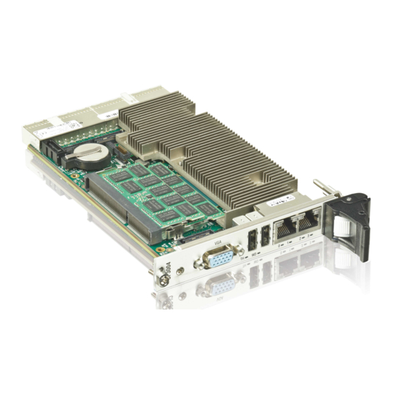
Summary of Contents for Kontron CP3004-SA
- Page 1 » User Guide « CP3004-SA Doc. ID: 1057-3535, Rev. 1.2 Date: March 18, 2019 The pulse of innovation...
-
Page 2: Revision History
Disclaimer Copyright © 2016 Kontron AG. All rights reserved. All data is for information purposes only and not guaranteed for legal purposes. Information has been carefully checked and is believed to be accurate; however, no responsibility is assumed for inaccuracies. Kontron and the Kontron logo and all other trademarks or registered trademarks are the property of their respective owners and are recognized. -
Page 3: Table Of Contents
User Guide CP3004-SA Contents Revision History ......................2 Imprint ........................2 Disclaimer ........................2 Contents ........................3 Tables ........................8 Figures ........................10 Warranty ........................11 Proprietary Note ......................11 Trademarks ......................11 Environmental Protection Statement ................11 Introduction ..................12 Board Overview .................. - Page 4 LED Control Register (LCTRL) ................. 56 3.3.16 General Purpose Output Register (GPOUT)............57 3.3.17 General Purpose Input Register (GPIN)............57 Power Considerations ................58 CP3004-SA Voltage Ranges................58 Power Consumption of the CP3004-SA.............. 58 Power Consumption of CP3004-SA Accessories ........... 59 www.kontron.com...
- Page 5 CP3004-XMC Extension Module .............. 71 Overview....................71 Technical Specifications ................71 CP3004-XMC Module Functional Block Diagram ..........72 Front Panel of the CP3004-SA with CP3004-XMC Module ........73 CP3004-XMC Module Layout................74 Module Interfaces ..................75 7.6.1 CFast Interface ................... 75 7.6.2...
- Page 6 Board Installation ..................86 11.3.1 Standard Board Insertion ................87 11.3.2 Standard Board Removal ................87 11.4 Installation of CP3004-SA Peripheral Devices ............ 88 11.4.1 SATA Flash Module Installation ..............90 11.4.2 Smart Extension Module Installation ............... 91 11.4.3 Installation of External SATA Devices .............. 91 11.4.4...
- Page 7 User Guide CP3004-SA 12.4.3 Examples of Startup Scripts ................. 106 12.4.3.1 Automatic Booting from USB Flash Drive ............106 12.4.3.2 Execute Shell Script on Other Harddrive ............106 12.4.3.3 Enable Watchdog and Control PXE Boot ............106 12.4.3.4 Handling the Startup Script in the SPI Boot Flash ..........107 12.5...
-
Page 8: Tables
CompactPCI Connector J1 Peripheral Slot Pinout ............33 CompactPCI Connector J2 Pinout (CP3004-SA Front I/O Vers.) ........34 Rear I/O CompactPCI Connector J2 Pinout (CP3004-SA Rear I/O Vers.) ......36 GPIO Signal Description ..................37 CompactPCI Rear I/O Connector J2 Signals ............... 37 COMA and COMB Signal Description ................ - Page 9 Main Setup Menu Sub-Screens and Functions ............98 Advanced Setup Menu Sub-Screens and Functions ............. 99 Security Setup Menu Functions ................101 Modes of Security ....................101 Save & Exit Setup Menu Sub-Screens and Functions ..........102 Boot Setup Menu Sub-Screens and Functions ............102 Kontron-Specific uEFI Shell Commands ..............104 www.kontron.com...
-
Page 10: Figures
CP3004-SA with Intel® Core™ i3-4112E, 1.8 GHz ............63 CP3004-HDD Module Functional Block Diagram ............66 Front Panel of the 8 HP and 12 HP CP3004-SA with CP3004-HDD Module ......67 CP3004-HDD Module Layout for 8 HP Board Version (Top View) ........68 CP3004-HDD Module Layout for 12 HP Board Version (Top View) ........ -
Page 11: Warranty
Warranty This Kontron product is warranted against defects in material and workmanship for the warranty period from the date of shipment. During the warranty period, Kontron will at its discretion decide to repair or replace defective products. Within the warranty period, the repair of products is free of charge as long as warranty conditions are observed. -
Page 12: Introduction
Two SODIMM sockets are available on the CP3004-SA to provide up to 16 GB dual-channel, DDR3L memory with Error Checking and Correction (ECC) running at 1600 MT/s. The graphics controller and the memory controller are integrated in the processor. -
Page 13: System Expansion Capabilities
CP3004-HDD module to provide an additional SATA connec- tor for a 2.5" SATA HDD / SSD device. The 12 HP CP3004-SA does not provide a CFast card socket. For further information about the CP3004-HDD module, refer to Chapter 6. -
Page 14: Functional Block Diagram
User Guide CP3004-SA 1.3.1 Functional Block Diagram Figure 1: CP3004-SA Functional Block Diagram www.kontron.com... -
Page 15: Front Panel
SPEED Note: For information regarding the front panel of the 8 HP or 12 HP CP3004-SA with a CP3004- HDD module, refer to Chapter 6. For information regarding the front panel of the 8 HP CP3004-SA with a CP3004-XMC mod- ule, refer to Chapter 7. -
Page 16: Board Layout
User Guide CP3004-SA 1.3.3 Board Layout Figure 3: 4 HP CP3004-SA Board Layout (Top View) SATA Flash J9 (Ch. B) Module DDR3L SODIMM Sockets J10 (Ch. A) Battery Smart Extension Module Intel® QM87 GbE A Intel® Core™ i7 GbE B... -
Page 17: Technical Specification
» 3.3 V or 5 V (universal PCI interface) » Support for up to seven peripheral slots (7x REQ/GNT signals) When installed in a peripheral slot, the CP3004-SA is isolated from the Compact- PCI bus. It receives power from the backplane and supports rear I/O. - Page 18 I/O expansion to 8 HP board version via the CP3004-XMC module: » PCI Express x8, x4 or x1 » CFast (SATA 3 Gb/s) I/O expansion of CP3004-SA via the Smart Extension Module (exceeds 4 HP): » SATA 3 Gb/s » USB 2.0...
- Page 19 User Guide CP3004-SA Table 1: CP3004-SA Main Specifications (Continued) FEATURES SPECIFICATIONS Front Panel Connectors » VGA: 15-pin D-Sub connector, J4 » USB: two 4-pin, type A connectors, J5 and J6 » Ethernet: dual RJ-45 connector, J7A/B Onboard Connectors » 7-pin, L-form standard SATA connector, J3 »...
- Page 20 4 HP. Board Weight 321 grams (4 HP CP3004-SA with heat sink, front panel, two 8 GB SODIMM mem- ory modules, and batter y, but without extension modules such as the SATA Flash module or the Smart Extension Module)
-
Page 21: Standards
5 (s) recovery time Note: Customers desiring to perform further environmental testing of the CP3004-SA must con- tact Kontron for assistance prior to performing any such testing. Boards without conformal coating must not be exposed to a change of temperature which can lead to condensation, as it may cause irreversible damage especially when the board is powered up again. -
Page 22: Related Publications
ANSI/VITA 42.0-200x XMC Switched Mezzanine Card Auxiliary Standard ANSI/VITA 42.3-2006 XMC PCI Express Protocol Layer Standard DisplayPort VESA DisplayPor t Standard Version 1.2a Platform Firmware Unif ied Extensible Firmware Interface (uEFI) specif ication, version 2.4 All Kontron products Product Safety and Implementation Guide, ID 1021-9142 www.kontron.com... -
Page 23: Functional Description
2 .1 P ro c e s s o r a n d C h i p s e t The CP3004-SA supports the Intel® Core™ i7-5700EQ, the Intel® Core™ i5-4410E, and the Intel® Core™ i3- 4112E processors in combination with the mobile Intel® QM87 Express Chipset. -
Page 24: Integrated Processor Graphics Controller
2 . 4 B a t te r y The CP3004-SA is provided with an UL-recognized CR2025, 3.0 V, “coin cell” lithium battery for the RTC. When a battery is installed, refer to the operational specifications of the battery as this determines the operating and storage temperature of the CP3004-SA. -
Page 25: Flash Memory
2.5.1 SPI Boot Flash for uEFI BIOS The CP3004-SA provides two 16 MB SPI boot flashes for two separate uEFI BIOS images, a standard SPI boot flash and a recovery SPI boot flash. The fail-over mechanism for the uEFI BIOS recovery can be controlled via the DIP switch SW1, switch 2. -
Page 26: System Status Leds
The General Purpose LEDs (LED3..0) are designed to indicate the boot-up POST code after which they are available to the application. If the LED3..0 are lit red during boot-up, a failure is indicated. In this event, please contact Kontron for further assistance. Table 6: General Purpose LEDs Function... -
Page 27: Usb Interfaces
USB 3.0 port, it is recommended to use an external hard disk drive. On the front panel, the CP3004-SA has two standard, type A, USB 2.0 connectors, J5 and J6. 2.7.3 VGA Inter face The CP3004-SA provides one standard VGA interface for connection to a monitor. -
Page 28: Gigabit Ethernet
+5V stand-by voltage on the rear I/O module must be available. The CP3004-SA does not turn off the main power supply after an operating system shutdown in order to support Wake-on-LAN. -
Page 29: Compactpci Interface
» CP3004-SA rear I/O version Please ensure that the correct version is stated on the order. If the CP3004-SA is ordered with rear I/O configuration, various I/O interfaces and signals are available via the CompactPCI connector J2, such as USB, SATA, GbE, VGA, COM, power and management signals. If the CP3004-SA is ordered with front I/O configuration, the I/O interfaces and signals mentioned above are isolated from the CompactPCI connector J2. -
Page 30: Power Ramping
CP3004-SA is hot pluggable. 2.7.8.5 Power Ramping On the CP3004-SA a special power controller is used to ramp up the onboard supply voltages. This is done to avoid transients on the +3.3V and +5V power supplies from the system. When the power supply is stable, the power controller generates an onboard reset to put the board into a defined state. -
Page 31: Compactpci Connectors J1 And J2
CompactPCI backplane connectors support guide lugs to en- sure a correct polarized mating (3.3 V or 5 V V(I/O) coding). The CP3004-SA supports universal (3.3 V and 5 V) PCI V(I/O) signaling voltages with one common termination resistor con- figuration. Therefore, the CP3004-SA can be inserted in both, 3.3 V and 5 V CompactPCI systems and provides itself no guide... -
Page 32: Compactpci Connectors J1 And J2 Pinouts
User Guide CP3004-SA 2.7.9.2 CompactPCI Connectors J1 and J2 Pinouts The CP3004-SA is provided with two 2 mm x 2 mm pitch female CompactPCI bus connectors, J1 and J2. Table 9: CompactPCI Connector J1 System Slot Pinout REQ64# ENUM# 3.3V... -
Page 33: Compactpci Connector J1 Peripheral Slot Pinout
A * indicates that the signal normally present at this pin is disconnected from the Com- pactPCI bus when the CP3004-SA is inserted in a peripheral slot. ** When the CP3004-SA is inserted in a peripheral slot, the function of the RST# signal can be enabled or disabled. -
Page 34: Compactpci Connector J2 Pinout (Cp3004-Sa Front I/O Vers.)
User Guide CP3004-SA Table 11: CompactPCI Connector J2 Pinout (CP3004-SA Front I/O Vers.) CLK6 CLK5 PRST# REQ6# GNT6# DEG# FAL# REQ5# GNT5# V(I/O) CLK4 GNT3# REQ4# GNT4# CLK2 CLK3 SYSEN# GNT2# REQ3# CLK1 REQ1# GNT1# REQ2# Note: The 64-bit CompactPCI signals are not used on the board and the 64-bit control and ad- dress signals are not terminated to V(I/O). -
Page 35: Optional Rear I/O Interface
Do not plug a rear I/O configured board in a backplane without rear I/O support. Failure to comply with the above will result in damage to your board. The CP3004-SA rear I/O provides the following interfaces (all signals are available on J2 only if the board is ordered with rear I/O functionality): »... -
Page 36: Rear I/O Compactpci Connector J2 Pinout (Cp3004-Sa Rear I/O Vers.)
User Guide CP3004-SA Table 12: Rear I/O CompactPCI Connector J2 Pinout (CP3004-SA Rear I/O Vers.) CLK6 USBA+ USBB+ USBA_PWR_5V CLK5 USBA- USBB- USBB_PWR_5V PWR_BTN# PWR_SLPS3# RIO_3.3V COMA_RXD COMA_DCD# COMA_DTR# GPI1/ COMA_CTS# COMB_CTS# COMA_TXD GPI0/ PRST# REQ6# GNT6# COMB_RXD COMA_DSR# COMA_RTS#... -
Page 37: Gpio Signal Description
The GPIO_CFG0 signal on the rear I/O module enables the user to select between COMB and GPIO inter- faces. Table 14: GPIO Signal Description SIGNAL DESCRIPTION GPIO_CFG0 0 = GPIO 1 = COMB Note: The default value is 1 if pin D4 is not connected on the rear I/ module (pull-up resistor to 3.3V on CP3004-SA). www.kontron.com... -
Page 38: Rear I/O Pin Description
User Guide CP3004-SA 2.7.9.4 Rear I/O Pin Descr iption Serial Ports The CP3004-SA provides two serial ports, COMA and COMB, both available on the rear I/O CompactPCI connector J2. Table 15: COMA and COMB Signal Description PIN on J2 SIGNAL... -
Page 39: Vga Signal Description
VGA signals are available either on the front VGA connector, J4, or on the rear I/O interface due to the implemented switch on the CP3004-SA. Switching over from front to rear I/O or vice versa is effected using the uEFI BIOS. -
Page 40: Gigabit Ethernet Signal Description
Gigabit Ethernet signals are available either on the front RJ-45 connector or on the rear I/O interface due to the implemented switches on the CP3004-SA. Both Gigabit Ethernet channels are individually switchable to front or rear I/O. Switching over from front to rear I/O or vice versa is effected using the uEFI BIOS settings (default: front I/O). -
Page 41: Usb Signal Description
USB power supply 5 V port B CP3004-SA 5 V (current limited) Power Supply and Power Management Signals The CP3004-SA provides the following power supply and power management signals to the rear I/O module. Table 21: Power Supply and Power Management Signal Description PIN on J2... -
Page 42: Configuration
User Guide CP3004-SA 3 Conf iguration 3 .1 D I P S w i t ch C o n f i g u r a t i o n The quad DIP switch SW1 provides the following switches for board configuration: POST code indica- tion, SPI boot flash selection, and uEFI BIOS configuration. -
Page 43: System Write Protection
3 . 2 S y s te m Wr i te P ro t e c t i o n The CP3004-SA provides write protection for non-volatile memories via the onboard configuration resistors JMP2 (only available upon request), the uEFI Shell and the CompactPCI rear I/O connector J2, pin B15 (RIO_SYS_WP#). -
Page 44: Status Register 0 (Stat0)
User Guide CP3004-SA 3.3.1 Status Register 0 (S TAT0) The Status Register 0 holds general / common status information. Table 24: Status Register 0 (STAT0) ADDRESS 0x280 NAME Reser ved BBEI BFSS DIP4 DIP3 DIP2 DIP1 ACCESS RESET BITFIELD DESCRIPTION... -
Page 45: Status Register 1 (Stat1)
1 = Installed in a peripheral slot CPCI system enumeration (ENUM signal): CENUM 0 = Indicates the insertion or removal of a hot swap peripheral board when the CP3004-SA operates as the system controller board 1 = No hot swap event... -
Page 46: Control Register 0 (Ctrl0)
User Guide CP3004-SA 3.3.3 Control Register 0 (CTRL0) The Control Register 0 holds a series of bits defining general/common configuration functions. Table 26: Control Register 0 (CTRL0) ADDRESS 0x282 VGAM NAME BFUS Reser ved ACCESS RESET 00000 BITFIELD DESCRIPTION 7 - 6... -
Page 47: Control Register 1 (Ctrl1)
The reset value of the SCOMA bit depends on the board version ordered. If the CP3004-SA is ordered as a rear I/O version, the reset value is 0. If the CP3004-SA is ordered as a front I/O version, an automatic switch over to the 8 HP extension module is processed per de- fault. -
Page 48: Device Protection Register (Dprot)
User Guide CP3004-SA 3.3.5 Device Protection Register (DPROT) The Device Protection Register holds the write protect signals for non-volatile devices. Table 28: Device Protection Register (DPROT) ADDRESS 0x284 SFWP JMP2 NAME Reserved BSWP SSWP ACCESS RESET BITFIELD DESCRIPTION System write protection status:... -
Page 49: Reset Status Register (Rstat)
User Guide CP3004-SA 3.3.6 Reset Status Register (RS TAT) The Reset Status Register is used to determine the host’s reset source. Table 29: Reset Status Register (RSTAT) ADDRESS 0x285 FPRS NAME PORS Reser ved CPRS WTRS ACCESS RESET 0000 BITFIELD... -
Page 50: Board Interrupt Configuration Register (Bicfg)
User Guide CP3004-SA 3.3.7 Board Interrupt Conf iguration Register (BICFG) The Board Interrupt Configuration Register holds a series of bits defining the interrupt routing. Table 30: Board Interrupt Configuration Register (BICFG) 0x286 ADDRESS NAME UICF CFICF CEICF CDICF Reserved WICF... -
Page 51: Status Register 2 (Stat2)
0000 = None / Smart Extension Module 0001 = CP3004-XMC extension module 0010 = CP3004-HDD extension module 0011...FFFF = Reser ved * The default value depends on the CP3004-SA version ordered (front I/O or rear I/O) and the rear I/O module used. www.kontron.com... -
Page 52: Board Id High-Byte Register (Bidh)
User Guide CP3004-SA 3.3.9 Board ID High-Byte Register (BIDH) Table 32: Board ID High-Byte Register (BIDH) ADDRESS 0x288 NAME BIDH ACCESS RESET 0xB4 BITFIELD DESCRIPTION 7 - 0 BIDH Board identif ication: CP3004-SA: 0xB430 Note: The Board ID Low Byte Register is located at the address 0x28D. -
Page 53: Watchdog Timer Control Register (Wtim)
User Guide CP3004-SA 3.3.12 Watchdog Timer Control Register (W TIM) Table 35: Watchdog Timer Control Register (WTIM) ADDRESS 0x28C WEN/WTR NAME ACCESS RESET 0000 BITFIELD DESCRIPTION Watchdog timer expired status bit: 0 = Watchdog timer has not expired 1 = Watchdog timer has expired. - Page 54 User Guide CP3004-SA The CP3004-SA has one Watchdog timer function with a programmable timeout ranging from 125 mil- liseconds to 4096 seconds. Failure to strobe the Watchdog timer within the programmed timeout delay results in a system reset or an interrupt.
-
Page 55: Board Id Low-Byte Register (Bidl)
User Guide CP3004-SA 3.3.13 Board ID Low-Byte Register (BIDL) Table 36: Board ID Low-Byte Register (BIDL) ADDRESS 0x28D NAME BIDL ACCESS RESET 0x30 BITFIELD DESCRIPTION 7 - 0 BIDL Board identif ication: CP3004-SA: 0xB430 Note: The Board ID High Byte Register is located at the address 0x288. -
Page 56: Led Control Register (Lctrl)
User Guide CP3004-SA 3.3.15 LED Control Register (LCTRL) The LED Control Register enables the user to switch on and off the front panel General Purpose LEDs. Table 38: LED Control Register (LCTRL) ADDRESS 0x291 NAME LCMD LCOL ACCESS RESET 0000... -
Page 57: General Purpose Output Register (Gpout)
The General Purpose Output Register holds the general purpose output signals of the rear I/O Compact- PCI connector J2. This register can only be used if the CP3004-SA is ordered as a rear I/O version and the rear I/O GPIO operation is configured through the dedicated rear transition module configuration signal on the CompactPCI connector J2. -
Page 58: Power Considerations
4 .1 C P 3 0 0 4 - S A Vo l t a g e Ra n ge s The CP3004-SA has been designed for optimal power input and distribution. Still it is necessary to ob- serve certain criteria essential for application stability and reliability. -
Page 59: Power Consumption Of Cp3004-Sa Accessories
4 . 3 Powe r C o n s u mp t i o n o f C P 3 0 0 4 - S A Acc e s s o r i e s The following table indicates the power consumption of the CP3004-SA accessories. -
Page 60: Maximum Power Consumption Of Xmc Modules
SA with CP3004-XMC extension module. 4 . 5 C u r re n t L i m i t s The CP3004-SA has a hot swap controller for the +3.3V and +5V input voltage. The trip current limits in case of catastrophic failure are: »... -
Page 61: Thermal Considerations
An airflow of 2.0 m/s to 3.0 m/s or a volumetric flow rate of 15 CFM to 20 CFM is a typical value for a standard Kontron ASM rack. For other racks or housings the available airflow will differ. The maximum ambient operating temperature must be determined for such environments. -
Page 62: Operational Limits For The Cp3004-Sa
The airflow is specified in m/s (meter-per-second) or in fps (feet-per-second) respectively. Conversion: 1 fps = 0.3048 m/s; 1 m/s = 3.28 fps The following figures illustrate the thermal operational limits of the CP3004-SA taking into consider- ation power consumption vs. ambient air temperature vs. airflow rate. -
Page 63: Cp3004-Sa With Intel® Core™ I5-4410E, 2.9 Ghz
User Guide CP3004-SA Figure 8: CP3004-SA with Intel® Core™ i5-4410E, 2.9 GHz recommended operating range 20 CFM at typical CPU workload 15 CFM at typical CPU workload CPU frequency (GHz) Figure 9: CP3004-SA with Intel® Core™ i3-4112E, 1.8 GHz Volumetric Flow Rate (CFM) -
Page 64: Cp3004-Hdd Extension Module
» Battery socket Note: If a CP3004-HDD module is used on the CP3004-SA, either the CP3004-SA or the CP3004- HDD module may be equipped with a battery. Using one battery on the CP3004-SA and one on the CP3004-HDD module simultaneously may result in premature discharge of the batteries. - Page 65 -40°C to +65°C With hard disk Note: When a battery is installed, refer to its operational specif ications as this may limit the operating and storage temperature of the CP3004-SA (see "Batter y" below). Batter y 3.0V lithium batter y for RTC; Battery type: UL-recognized CR2025...
-
Page 66: Cp3004-Hdd Module Functional Block Diagram
User Guide CP3004-SA 6 . 3 C P 3 0 0 4 - H D D M o du l e Fu n c t i o n a l B l o ck D i a g r a m Figure 10: CP3004-HDD Module Functional Block Diagram www.kontron.com... -
Page 67: Front Panel Of The Cp3004-Sa With Cp3004-Hdd Module
6 . 4 Fro n t Pan e l o f th e C P 3 0 0 4 - S A w i th C P 3 0 0 4 - H D D M o d u l e Figure 11: Front Panel of the 8 HP and 12 HP CP3004-SA with CP3004-HDD Module... -
Page 68: Cp3004-Hdd Module Layout
User Guide CP3004-SA 6 . 5 C P 3 0 0 4 - H D D M o du l e L ay o u t Figure 12: CP3004-HDD Module Layout for 8 HP Board Version (Top View) HDD LED & Reset Button... -
Page 69: Module Interfaces
User Guide CP3004-SA Figure 14: SATA Adapter for 2.5” SATA HDD/SSD (Top view) 6 . 6 M o d u l e I n te r fa c e s 6.6.1 DisplayPor t Inter faces The CP3004-HDD provides two standard DisplayPort interfaces for connection to two monitors. The in- terfaces are implemented as standard DisplyaPort donncecors, J1 und J2, on the front panel. -
Page 70: Serial Port
6.6.5 CFast Inter face To enable flexible flash expansion, a standard CFast card socket, J4, is available on the 8 HP CP3004- SA with CP3004-HDD. However, the 12 HP CP3004-SA does not provide CFast card support. 6.6.6 SATA Inter face The CP3004-HDD extension module provides two SATA connectors, one 29-pin standard SATA connec- tor, J6, for connection to 2.5”... -
Page 71: Cp3004-Xmc Extension Module
15 W can be used on the CP3004-XMC module. Note: If the CP3004-XMC module is mounted on the CP3004-SA, the SATA Flash module / Smart Extension Module cannot be used with the CP3004-SA. 7.2 Te c h n i c a l S p e c i f i c a t i o n s... -
Page 72: Cp3004-Xmc Module Functional Block Diagram
User Guide CP3004-SA 7.3 C P 3 0 0 4 - X M C M o d u l e Fu n c t i o n a l B l o c k D i a g r a m Figure 16: CP3004-XMC Module Functional Block Diagram www.kontron.com... -
Page 73: Front Panel Of The Cp3004-Sa With Cp3004-Xmc Module
7.4 Fro n t Pa n e l o f th e C P 3 0 0 4 - S A w i th C P 3 0 0 4 - X M C M o d u l e Figure 17: Front Panel of the 8 HP and 12 HP CP3004-SA with CP3004-XMC Module... -
Page 74: Cp3004-Xmc Module Layout
User Guide CP3004-SA 7.5 C P 3 0 0 4 - X M C M o d u l e L ay o u t Figure 18: CP3004-XMC Module Layout for 8 HP Board Version (Top View) HDD LED & Reset Button... -
Page 75: Module Interfaces
User Guide CP3004-SA 7.6 M o d u l e I n t e r f a c e s 7.6.1 CFast Inter face To enable flexible flash expansion, a standard CFast card socket, J2, is available on the 8 HP CP3004- SA with CP3004-XMC. -
Page 76: Cp-Rio3-04 Rear Transition Module
The CP3004-SA provides optional rear I/O connectivity for peripherals. Some standard PC interfaces are implemented and assigned to the front panel and to the rear I/O connector J2 on the CP3004-SA. When the CP-RIO3-04 rear transition module is used, some signals of main board/front panel connec- tors are routed to the module interface. -
Page 77: Cp-Rio3-04 Front Panels
User Guide CP3004-SA 8 . 3 C P- R I O 3 - 0 4 Fro n t Pa n e l s Figure 20: CP-RIO3-04 4HP and 8HP Front Panels CP-RIO3-04 CP-RIO3-04 www.kontron.com... -
Page 78: Cp-Rio3-04 Rear Transition Module Layout
User Guide CP3004-SA 8 . 4 C P- R I O 3 - 0 4 Re a r Tr a n s i t i o n M o d u l e L ay o u t Figure 21: 4HP CP-RIO3-04 Rear Transition Module Layout... -
Page 79: 8Hp Cp-Rio3-04 Rear Transition Module Layout
User Guide CP3004-SA Figure 22: 8HP CP-RIO3-04 Rear Transition Module Layout ribbon Peripheral cable (COM1) Control CPCI COMA (COM1) Dual GbE ribbon cable (COM1) COMB (COM2) SATA www.kontron.com... -
Page 80: Module Interfaces
User Guide CP3004-SA 8 . 5 M o d u l e I n te r fa c e s 8.5.1 USB Inter faces The CP-RIO3-04 rear transition module provides two standard, type A, USB 2.0 connectors, J11 and J12, on the front panel. -
Page 81: Peripheral Control Interface
User Guide CP3004-SA 8.5.5 Per ipheral Control Inter face A power supply with power management can be connected to the CP-RIO3-04 rear transition module via the peripheral control connector J13. The following table provides pinout information for the peripheral control connector J13. Refer to the module layout for connector and pin locations. -
Page 82: Rear I/O Interface On Compactpci Connector Rj2
User Guide CP3004-SA 8.5.7 Rear I/O Inter face on CompactPCI Connector rJ2 The CP-RIO3-04 rear transition module conducts a wide range of I/O signals through the rear I/O connector rJ2. Note: To support the rear I/O feature, a 3U CompactPCI backplane with rear I/O support is re- quired. -
Page 83: Rear I/O Signal Description
User Guide CP3004-SA Table 51: Rear I/O CompactPCI Connector rJ2 Pinout USBA+/bi USBB+/bi USBA_PWR_5V/ in GND USBA-/bi USBB-/bi USBB_PWR_5V/ in GND PWR_BTN#/out PWR_SLPS3#/in RIO_3.3V/in COMA_RXD/out COMA_DCD#/out COMA_DTR#/in COMB_CTS# /out COMA_CTS#/out COMA_TXD/in COMB_RXD/out COMA_DSR#/out COMA_RTS#/in COMA_RI#/out PWR_5VSTDBY/ out RSV IPA_DA+/bi IPA_DA-/bi... -
Page 84: Sata Flash Module
9 .1 O ve r v i ew The 4 HP CP3004-SA provides an optional SATA Flash module with up to 32 GB NAND flash memory. The SATA Flash module is connected to the CP3004-SA via the J12 connector located on the CP3004-SA and the J1 connector located on the SATA Flash module. -
Page 85: Smart Extension Module
10 Smar t Extension Module 10.1 O ve r v i ew For the 4 HP CP3004-SA there is an optional Smart Extension Module for facilitating the connection to system-internal USB and SATA devices. The Smart Extension Module includes one SATA cable connector as well as one USB 2.0 connector. -
Page 86: Installation
11. 3 B o a r d I n s t a l l a t i o n The CP3004-SA is designed for use either as a CompactPCI system controller or as an autonomous CPU board in a CompactPCI peripheral slot. -
Page 87: Standard Board Insertion
Failure to comply with the above may result in improper operation or damage to other sys- tem components, e.g. operating system failure, data loss, uncontrolled processing, etc. Note: In order to use the hot plug function of the CP3004-SA, a hot swap-capable backplane is required. 11.3.1 Standard Board Inser tion Prior to following the steps below, ensure that the safety requirements are met. -
Page 88: Installation Of Cp3004-Sa Peripheral Devices
11. 4 I n s t a l l a t i o n o f C P 3 0 0 4 - S A Pe r i p h e r a l D e v i c e s The CP3004-SA is designed to accommodate various peripheral devices, such as USB devices, SATA de- vices, a CFast card, etc. -
Page 89: Hp Cp3004-Sa With Cp3004-Hdd Module
Figure 28: 8 HP CP3004-SA with CP3004-HDD Module 2.5” SATA HDD/SSD CP3004-HDD Module CFast Card 7-pin SATA Cable Connector Figure 29: 12 HP CP3004-SA with CP3004-HDD Module and SATA Adapter Module 7-pin SATA 2 x 2.5” SATA HDD/SSD Cable Connector SATA Adapter Module CP3004-HDD Module www.kontron.com... -
Page 90: Sata Flash Module Installation
This optionally available module must be physically installed on the CP3004-SA prior to installation of the CP3004-SA in a system. During installation it is necessary to ensure that the SATA Flash module is properly seated in the onboard connector J12, i.e. the pins are aligned correctly and not bent. -
Page 91: Smart Extension Module Installation
CP3004-SA 11.4.2 Smar t Extension Module Installation A Smart Extension Module may be connected to the 4 HP CP3004-SA via the onboard connector J14. This optionally available module must be physically installed on the CP3004-SA prior to installation of the CP3004-SA in a system. -
Page 92: Xmc Module Installation
The 8 HP CP3004-SA equipped with the CP3004-XMC module provides an XMC connector, J1, for con- nection to an XMC module such as the Kontron XMC 401, XMC402, etc. The XMC module must be installed on the CP3004-XMC prior to installation of the CP3004-SA with the CP3004-XMC in a system. -
Page 93: Screws Securing The Xmc Module To The Cp3004-Xmc Extension Module
User Guide CP3004-SA Figure 32: Screws Securing the XMC Module to the CP3004-XMC Extension Module Figure 33: CP3004-SA Board with CP3004-XMC Extension Module and XMC Module CP3004-XMC Extension Module XMC Module CP3004-SA Board www.kontron.com... -
Page 94: Cp3004-Sa With Front Panel, Cp3004-Xmc Extension Module And Xmc Module
User Guide CP3004-SA Figure 34: CP3004-SA with Front Panel, CP3004-XMC Extension Module and XMC Module Ensure that no power is applied to the CP3004-SA and disconnect any interfacing cables that may be connected to the board before proceeding. Note: Even though power may be removed from the system, the CP3004-SA front panel cables and, when installed, the RIO transition module front panel cables may have power applied which comes from an external source. -
Page 95: Cfast Card Installation
Please refer to Figure 34 for further information on this instruction. Remove the XMC slot cover plate from the XMC bezel cutout of the CP3004-SA front panel, if mounted. Attach the front panel to the board assembly and secure it with the screws (a), (b), (c), (d), (e), and (f) removed in step 2. -
Page 96: Rear I/O Device Installation
11. 5 B a t te r y Rep l a c e m e n t The CP3004-SA RTC may be backed up using a single 3.0 V “coin cell” lithium battery from one of two possible points of installation: »... -
Page 97: Uefi Bios
<RETURN>, and proceed with step 5. A Setup menu will appear. The CP3004-SA uEFI BIOS Setup program uses a hot key-based navigation system. A hot key legend bar is located on the bottom of the Setup screens. The following table provides information concerning the usage of these hot keys. -
Page 98: Setup Menus
User Guide CP3004-SA 12 . 2 S e t u p M e n u s The Setup utility features four menus listed in the selection bar at the top of the screen: » Main » Advanced » Security »... -
Page 99: Advanced Setup Menu
User Guide CP3004-SA 12.2.2 Advanced Setup Menu The Advanced Setup menu provides sub-screens and functions for advanced configuration. Note: Setting items on this screen to incorrect values may cause the system to malfunction. Table 57: Advanced Setup Menu Sub-Screens and Functions... - Page 100 User Guide CP3004-SA Table 57: Advanced Setup Menu Sub-Screens and Functions (Continued) SUB-SCREEN FUNCTION DESCRIPTION Serial Port Console Serial Por t for Out-of-Band Management / Windows Emergency Management Services (EMS) Redirection Console Redirection Enables / Disables console redirection Console Redirection Settings...
-
Page 101: Security Setup Menu
CP3004-SA 12.2.3 Secur ity Setup Menu The Security Setup menu provides information about the passwords and functions for specifying the security settings. The passwords are case-sensitive. The CP3004-SA provides no factory-set passwords. Table 58: Security Setup Menu Functions FUNCTION DESCRIPTION Password Description Read-only f ield. -
Page 102: Save & Exit Setup Menu
User Guide CP3004-SA Table 60: Boot Setup Menu Sub-Screens and Functions SUB-SCREEN FUNCTION DESCRIPTION Boot Conf iguration Fast Boot Enables/Disables boot with initialization of a minimal set of devices required to launch active boot option. Boot Option Pr iori- Boot option #1..2... -
Page 103: The Uefi Shell
12 . 3 T h e u E F I S h e l l The Kontron uEFI BIOS features a built-in and enhanced version of the uEFI Shell. For a detailed de- scription of the available standard shell scripting refer to the EFI Shell User’s Guide. For a detailed de- scription of the available standard shell commands, refer to the EFI Shell Command Manual. -
Page 104: Kontron-Specific Uefi Shell Commands
User Guide CP3004-SA 12.3.2 Kontron-Specif ic uEFI Shell Commands The Kontron uEFI implementation provides the following additional commands related to the specific HW features of the Kontron system. Table 62: Kontron-Specific uEFI Shell Commands COMMAND DESCRIPTION kboardconf ig Conf igures non-volatile board settings, such as: »... - Page 105 Conf igures the Kontron onboard Watchdog This command is used to enable the Kontron onboard Watchdog with reset target before OS boot. This can be used to detect if the OS fails to boot and react by reset. The uEFI Shell commands are not case-sensitive. Each uEFI Shell command is provided with a detailed online help that can be invoked by entering “<cmd>...
-
Page 106: Uefi Shell Scripting
It searches for scripts and executes them in the following order: Kontron flash-stored startup script If there is no Kontron flash-stored startup script present, the uEFI-specified startup.nsh script is used. This script must be located on the root of any of the attached FAT formatted disk drive. -
Page 107: Handling The Startup Script In The Spi Boot Flash
User Guide CP3004-SA The following sample start-up script shows two uEFI Shell environment variables, wdt_enable and pxe_first, used to control the boot process and the Watchdog. echo -off echo “Executing sample startup.nsh...” if %wdt_enable% == “on” then kwdt -t 15 echo “Watchdog enabled”... -
Page 108: Updating The Uefi Bios
12 . 5 Up d a t i n g th e u E F I B I O S The CP3004-SA has two SPI boot flashes programmed with the uEFI BIOS, a standard SPI boot flash and a recovery SPI boot flash. The basic idea behind that is to always have at least one working uEFI BIOS flash available regardless if there have been any flashing errors or not. - Page 109 User Guide CP3004-SA CORPORATE OFFICES Europe, Middle East & Africa North America Asia Pacific Lise-Meitner-Str. 3-5 14118 Stowe Drive 17 Building,Block #1, ABP. 86156 Augsburg Poway, CA 92064-7147 188 Southern West 4th Ring Road Germany Beijing 100070, P.R.China Tel.: + 49 (0) 821 / 4086 0 Tel.: + 1 888 294 4558...
Need help?
Do you have a question about the CP3004-SA and is the answer not in the manual?
Questions and answers