Table of Contents
Advertisement
Advertisement
Table of Contents

Related Manuals for Kontron CP307


Summary of Contents for Kontron CP307
- Page 1 Artisan Technology Group is your source for quality new and certified-used/pre-owned equipment SERVICE CENTER REPAIRS WE BUY USED EQUIPMENT • FAST SHIPPING AND DELIVERY Experienced engineers and technicians on staff Sell your excess, underutilized, and idle used equipment at our full-service, in-house repair center We also offer credit for buy-backs and trade-ins •...
- Page 2 CP307 3U CompactPCI Processor Board based on the Intel® Core™ Duo Processor and the Intel® Core™2 Duo Processor with the Intel® 945GM Express Chipset Doc. ID: 34424, Rev. 3.0 December 17, 2008 User Guide Artisan Technology Group - Quality Instrumentation ... Guaranteed | (888) 88-SOURCE | www.artisantg.com...
-
Page 3: Imprint
Disclaimer Copyright © 2006 Kontron AG. All rights reserved. All data is for information purposes only and not guaranteed for legal purposes. Information has been carefully checked and is believed to be accurate; however, no responsibility is assumed for inaccuracies. Kontron and the Kontron logo and all other trademarks or registered trademarks are the property of their respective own- ers and are recognized. -
Page 4: Table Of Contents
Front Panel ..................1 - 8 1.5.3 Board Layout .................. 1 - 9 1.6 Technical Specification ................1 - 10 1.7 Kontron Software Support ..............1 - 16 1.8 Standards ....................1 - 16 1.9 Related Publications ................1 - 17 ID 34424, Rev. 3.0 Page iii Artisan Technology Group - Quality Instrumentation ... - Page 5 3.1 Safety Requirements ................3 - 3 3.2 CP307 Initial Installation Procedures ............3 - 4 3.3 Standard Removal Procedures ..............3 - 5 3.4 Hot Swap Procedures ................3 - 5 3.5 Installation of CP307 Peripheral Devices ..........3 - 5 3.5.1 CompactFlash Installation ...............3 - 5 3.5.2 USB Device Installation ..............3 - 6...
- Page 6 Power Supply Units ................ 5 - 4 5.2 Power Consumption ................5 - 7 5.3 Power Consumption of CP307 Accessories ........... 5 - 9 5.4 Start-Up Currents of the CP307 .............. 5 - 9 Thermal Considerations ............6 - 3 6.1 Board Internal Thermal Regulation ............
- Page 7 A.2 Technical Specifications ................. A - 4 A.3 CP307-HDD Module Functional Block Diagram ........A - 5 A.4 Front Panel of 8HP CP307 for CP307-HDD Module ......A - 6 A.5 CP307-HDD Module Layout ..............A - 7 A.6 Module Interfaces (Front Panel and Onboard) ........A - 8 A.6.1...
- Page 8 CP307 Preface B.5.3 Gigabit Ethernet Interface ...............B - 9 B.5.4 COM Interface ................B - 10 B.5.5 Peripheral Control Interface ............B - 11 B.5.6 Serial ATA Interfaces SATA1 and SATA3 ........B - 12 B.5.7 Rear I/O interface on Compact PCI Connector rJ2 ......B - 13 ID 34424, Rev.
- Page 9 Preface CP307 This page has been intentionally left blank. Page viii ID 34424, Rev. 3.0 Artisan Technology Group - Quality Instrumentation ... Guaranteed | (888) 88-SOURCE | www.artisantg.com...
-
Page 10: List Of Tables
2-14 CompactPCI Bus Connector J1 Pinout ........... 2 - 18 2-15 64-bit CompactPCI Bus Connector J2 Pinout (CP307 Front I/O Vers.) .. 2 - 19 2-16 Rear I/O CompactPCI Bus Connector J2 Pinout (CP307 Rear I/O Vers.) 2 - 21 2-17 GPIO Signal Description ................. - Page 11 Input Voltage Characteristics ..............5 - 5 Power Consumption: CP307 with DOS ............5 - 8 Power Consumption: CP307 with Linux / Win.® XP in IDLE Mode ... 5 - 8 Power Consumption: CP307 TDP at 75% ..........5 - 8 Power Consumption: CP307 TDP at 100% ..........
- Page 12 CP307 with Aluminum Heat Sink ............. 6 - 5 CP307 with Copper Heat Sink ..............6 - 5 Operational Limits for the CP307 with Core™ Duo 1.2 GHz ....6 - 7 Operational Limits for the CP307 with Core™ Duo 1.66 GHz ....6 - 8 Operational Limits for the CP307 with Core™...
- Page 13 Preface CP307 USB Connectors J11/J12 ................ B - 7 D-Sub VGA Con. J7 ................B - 8 Dual Gigabit Ethernet Connector J10A/B ..........B - 9 COM Connectors J2a (COM1) and J3a (COM2) ........B - 10 Serial Port Connectors J2 (COM1) and J3 (COM2) ......B - 10 Peripheral Connector J13 ...............
-
Page 14: Proprietary Note
Preface Proprietary Note This document contains information proprietary to Kontron. It may not be copied or transmitted by any means, disclosed to others, or stored in any retrieval system or media without the prior written consent of Kontron or one of its authorized agents. -
Page 15: Explanation Of Symbols
Preface CP307 Explanation of Symbols Caution, Electric Shock! This symbol and title warn of hazards due to electrical shocks (> 60V) when touching products or parts of them. Failure to observe the pre- cautions indicated and/or prescribed by the law may endanger your life/health and/or result in damage to your material. -
Page 16: For Your Safety
However, the life expectancy of your product can be drastically reduced by improper treatment during unpacking and installation. Therefore, in the interest of your own safety and of the correct operation of your new Kontron product, you are requested to conform with the following guidelines. -
Page 17: General Instructions On Usage
CP307 General Instructions on Usage In order to maintain Kontron’s product warranty, this product must not be altered or modified in any way. Changes or modifications to the device, which are not explicitly approved by Kontron and described in this manual or received from Kontron’s Technical Support as a special handling instruction, will void your warranty. -
Page 18: Two Year Warranty
As a result, the products are sold “as is,” and the responsibility to ensure their suitability for any given task remains that of the purchaser. In no event will Kontron be liable for direct, indirect or consequential damages resulting from the use of our hardware or software products, or documentation, even if Kontron were advised of the possibility of such claims prior to the purchase of the product or during any period since the date of its purchase. - Page 19 Preface CP307 This page has been intentionally left blank. Page xviii ID 34424, Rev. 3.0 Artisan Technology Group - Quality Instrumentation ... Guaranteed | (888) 88-SOURCE | www.artisantg.com...
-
Page 20: Introduction
CUSTOMER SPECIFIC CP307 Introduction Chapter Introduction ID 34424, Rev. 3.0 Page 1 - 1 Artisan Technology Group - Quality Instrumentation ... Guaranteed | (888) 88-SOURCE | www.artisantg.com... - Page 21 CUSTOMER SPECIFIC Introduction CP307 This page has been intentionally left blank. Page 1 - 2 ID 34424, Rev. 3.0 Artisan Technology Group - Quality Instrumentation ... Guaranteed | (888) 88-SOURCE | www.artisantg.com...
-
Page 22: System Overview
(PICMG). Many system-relevant CompactPCI features that are specific to Kontron CompactPCI systems may be found described in the Kontron CompactPCI System Manual. Please refer to the section “Related Publications” at the end of this chapter for the relevant ordering information. -
Page 23: Board Overview
1.2.1 Board Introduction The CP307 is a highly integrated, 3U, 4 HP or 8 HP, lead-free CompactPCI system controller board. It has been designed to support the Intel® Core™ Duo and the Intel® Core™2 Duo processors with frequencies ranging from 1.2 GHz up to 2.16 GHz providing 533/667 MHz Front Side Bus (FSB) in 479 µFCBGA packaging. -
Page 24: Board-Specific Information
Introduction 1.2.2 Board-Specific Information The CP307 is a CompactPCI single-board computer based on Intel’s Dual Core™ processor technology and is specifically designed for use in highly integrated platforms with solid mechanical interfacing for a wide range of industrial environment applications. -
Page 25: Optional Modules
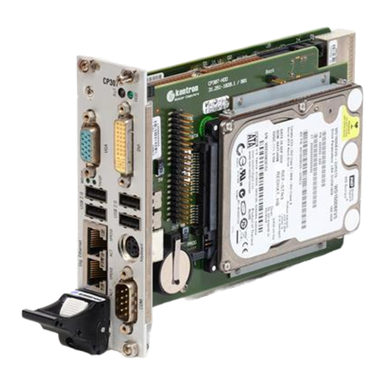
1.3.1 CP307-HDD Module The CP307-HDD module for the 8 HP CP307 version provides legacy PC I/O ports. It includes one digital DVI port, two USB 2.0 ports, one COM port, a PS/2 keyboard and mouse port, one IDE connector, and one CompactFlash socket. A SATA hard disk interface is also available for mounting a 2.5”... -
Page 26: Functional Block Diagram
CUSTOMER SPECIFIC CP307 Introduction 1.5.1 Functional Block Diagram Figure 1-1: CP307 Functional Block Diagram Front Reset, Power Clock Supply Switch Rear DDR2 SDRAM Soldered Up to 2GB Graphic Memory Core Duo / Controller 533/667MHz Core 2 Duo 533/667MHz, 64-bit GMCH... -
Page 27: Front Panel
SPEED ON (orange): 1000 Mbit SPEED ON (green): 100 Mbit SPEED OFF: 10 Mbit Note ... For detailed information on the 8HP CP307 version, refer to Appendix A, CP307-HDD module. Page 1 - 8 ID 34424, Rev. 3.0 Artisan Technology Group - Quality Instrumentation ... Guaranteed | (888) 88-SOURCE | www.artisantg.com... -
Page 28: Board Layout
CUSTOMER SPECIFIC CP307 Introduction 1.5.3 Board Layout Figure 1-3: 4 HP CP307 Board Layout (Top View) SATA CompactFlash Socket GP LEDs J11A Dual Gigabit Ethernet J11B Battery Figure 1-4: 4 HP CP307 Board Layout (Bottom View) ID 34424, Rev. 3.0 Page 1 - 9 Artisan Technology Group - Quality Instrumentation ... -
Page 29: Technical Specification
Introduction CP307 Technical Specification Table 1-2: CP307 4HP Version Main Specifications CP307 SPECIFICATIONS The CP307 supports the following microprocessors: • Intel® Core™ Duo • Intel® Core™ Duo processor U2500 (ULV), 1.2 GHz, 533 MHz FSB, 2 MB L2 cache •... - Page 30 Enhanced DMA controller, interrupt controller, and timer functions • Integrated IDE controller Ultra ATA/100/66/33 and PIO mode • USB 2.0 host interface with up to six USB ports available on the CP307 • SATA Host Controller with four ports, 3 Gbit/s transfer rate and RAID 0/1/5/10 support •...
- Page 31 General Purpose signals Hot Swap The CP307 is not hot-swappable but supports the addition and removal of other boards whilst in a powered-up state. Individual clocks for each slot and Enum signal handling are in compliance with the PICMG 2.1 Hot Swap Specification.
- Page 32 Mass Storage SATA: Integrated Serial ATA Host Controllers • One onboard port (SATA connector) • One port available on the CP307-HDD module (8HP) for 2.5” HDD • Two ports available on Rear I/O • Data transfer rate up to 3 Gbit/s •...
- Page 33 Board serial number is saved within the EEPROM • PC Health Monitoring Operating Systems There are various operating systems available for the CP307. For detailed infor- mation, please contact Kontron. Page 1 - 14 ID 34424, Rev. 3.0 Artisan Technology Group - Quality Instrumentation ... Guaranteed | (888) 88-SOURCE | www.artisantg.com...
- Page 34 Depending on the processor used, there are two types of heat sinks available with the CP307: • Aluminum heat sink for the CP307 with Core™ Duo 1.2 GHz, Core™ Duo 1.66 GHz and Core™2 Duo 1.5 GHz • Copper heat sink for the CP307 with Core™ Duo 2.0 GHz and Core™2 Duo 2.16 GHz...
-
Page 35: Kontron Software Support
CP307 Kontron Software Support Kontron is one of the few CompactPCI and VME vendors providing inhouse support for most of the industry-proven real-time operating systems that are currently available. Due to its close relationship with the software manufacturers, Kontron is able to produce and support BSPs and drivers for the latest operating system revisions thereby taking advantage of the changes in technology. -
Page 36: Related Publications
Boards CompactPCI System Management Specification PICMG 2.9 Rev. 1.0 CompactPCI Hot Swap Specification PICMG 2.1 Rev. 2.0 Hot Swap Specification PICMG 2.1 Kontron’s CompactPCI System Manual, ID 19954 CompactFlash Cards CF+ and CompactFlash Specification Revision 2.0 Serial ATA Serial ATA 1.0a Specification ID 34424, Rev. - Page 37 CUSTOMER SPECIFIC Introduction CP307 This page has been intentionally left blank. Page 1 - 18 ID 34424, Rev. 3.0 Artisan Technology Group - Quality Instrumentation ... Guaranteed | (888) 88-SOURCE | www.artisantg.com...
-
Page 38: Functional Description
CP307 Functional Description Chapter Functional Description ID 34424, Rev. 3.0 Page 2 - 1 Artisan Technology Group - Quality Instrumentation ... Guaranteed | (888) 88-SOURCE | www.artisantg.com... - Page 39 Functional Description CP307 This page has been intentionally left blank. Page 2 - 2 ID 34424, Rev. 3.0 Artisan Technology Group - Quality Instrumentation ... Guaranteed | (888) 88-SOURCE | www.artisantg.com...
-
Page 40: Cpu, Memory And Chipset
CPU, Memory and Chipset 2.1.1 The CP307 supports the latest Intel® Core™ Duo and Intel® Core™2 Duo processor family up to speeds of 2.16 GHz with up to 667 MHz FSB. The Intel® Core™ Duo consists of two cores and up to 2 MB L2 cache shared by both cores. -
Page 41: Processors Supported On The Cp307
Functional Description CP307 The following tables provide information about the Intel® Core™ Duo and the Intel® Core™2 Duo processors supported on the CP307. Table 2-1: Processors Supported on the CP307 Core™ Duo Core™ Duo Core™ Duo Core™2 Duo Core™2 Duo SPEED 1.2 GHz (ULV... -
Page 42: Memory
2.1.2 Memory The CP307 supports a dual-channel DDR2 memory without Error Checking and Correcting (ECC) running at 667 MHz (PC2-5300-CL5). Channel A is soldered. Channel B provides one 200-pin SODIMM socket for a DDR2 SODIMM module. The maximum memory size per chan- nel is 2 GB. -
Page 43: Intel® 945Gm Express Chipset Overview
Functional Description CP307 2.1.3 Intel® 945GM Express Chipset Overview The Intel® 945GM Express Chipset consists of the following devices: • Mobile Intel® 945GM Express Graphics Memory Controller Hub (945GM Express GMCH) • I/O Controller Hub 7 (ICH7-R) The 945GM Express GMCH provides the processor interface for the Intel® Core™ Duo and the Intel®... -
Page 44: I/O Controller Hub Ich7-R
CMOS RAM. Features include an alarm function, programmable periodic interrupt and a 100-year calendar. All battery-backed CMOS RAM data remains stored in an additional EEPROM. This prevents data loss in case the CP307 is operated without battery. • Counter/Timer Three 8254-style counter/timers are included on the CP307 as defined for the PC/AT. -
Page 45: Battery
CP307 2.2.3 Battery The CP307 is provided with a 3.0 V “coin cell” lithium battery for the RTC. Note ... If a CP307-HDD module is used on the CP307, either the CP307 or the CP307-HDD module may be equipped with a battery. -
Page 46: Reset
2.2.4 Reset The CP307 is automatically reset by a precision voltage monitoring circuit that detects a drop in voltage below the acceptable operating limit of 4.45 V for the 5 V line and below 2.8 V for the 3.3 V line. Other reset sources include the watchdog timer and the local push-button switch (only on 8HP). -
Page 47: Serial Eeprom
BIOS become available. 2.2.8.2 CompactFlash Socket A CompactFlash mezzanine adapter CP307-CF is installed on the CP307 4HP versions to provide CompactFlash interfacing. CompactFlash is a very small removable mass storage device. It provides true IDE functionality compatible with the 16-bit ATA/ATAPI-4 interface. -
Page 48: Compactflash Connector Pinout
CP307 Functional Description The following table provides the pinout for the CompactFlash connector on the CP307-CF mod- ule. Table 2-7: CompactFlash Connector Pinout FUNCTION SIGNAL SIGNAL FUNCTION Ground Signal Data 3 Data 4 Data 5 Data 6 Data 7 Chip Select 0... -
Page 49: Board Interfaces
Kontron. If the WD/GP LED and the TH/GP LED keep flashing during BIOS initialization, a POST code is indicated. For information on the POST Codes, refer to the CP307 BIOS Guide, Chapter 10, POST Codes. The following table defines the blinking intervals of the WD/GP LED and the TH/GP LED. -
Page 50: Usb Interfaces
USB Interfaces The CP307 supports six USB 2.0 ports (two front I/O, two front I/O on the 8HP version, and two on the Rear I/O module). On the USB 2.0 Rear I/O ports, it is strongly recommended to use a cable below 3 meters in length for USB 2.0 devices. -
Page 51: D-Sub Vga Connector J6 Pinout
Ground signal 4,11 * Pin 10 is normally defined as Ground but is used on the CP307 as detection signal of a con- nected monitor if the BIOS setting for the CP307 is “AUTO” (the BIOS default setting is “FRONT”). -
Page 52: Gigabit Ethernet
2.3.4 Gigabit Ethernet Figure 2-4: Dual Gigabit Ethernet Connector J11A/B The CP307 board includes two 10Base-T/100Base- TX/1000Base-T Ethernet ports based on two Intel® 82573L Gigabit Ethernet controllers, which are con- nected to the x1 PCI Express interfaces of the ICH7-R. -
Page 53: Serial Ata Connector J4 (Sata0)
10Base-T. 2.3.5 Serial ATA Connector J4 (SATA0) The CP307 is equipped with a SATA connector, J4, which is used to connect standard HDDs and other SATA devices to the CP307. Figure 2-5: SATA Connector J4 Table 2-12: SATA Connector J4 Pinout... -
Page 54: Compactpci Bus Interface
Color coded keys prevent inadvertent installation of a 5 V board into a 3.3 V slot and vice versa. The CP307 board may be ordered as either a 3.3 V or a 5 V version. Backplane connectors are always keyed according to the signaling (VIO) level. - Page 55 Functional Description CP307 2.3.6.2 CompactPCI Connectors J1 and J2 Pinouts The CP307 is provided with two 2 mm x 2 mm pitch female CompactPCI bus connectors, J1 and J2. Table 2-14: CompactPCI Bus Connector J1 Pinout ROW Z ROW A...
- Page 56 CP307 Functional Description Table 2-15: 64-bit CompactPCI Bus Connector J2 Pinout (CP307 Front I/O Vers.) ROW Z ROW A ROW B ROW C ROW D ROW E ROW F CLK6 CLK5 PRST# REQ6# GNT6# DEG# FAL# REQ5# GNT5# AD[35] AD[34]...
-
Page 57: Optional Rear I/O Interface
CPU in the rack as there is practically no cabling on the CPU board. For the system Rear I/O feature a special backplane is necessary. The CP307 with Rear I/O is compatible with all standard CompactPCI passive backplanes with Rear I/O support on the system slot. -
Page 58: Rear I/O Compactpci Bus Connector J2 Pinout (Cp307 Rear I/O Vers.)
REQ1# GNT1# REQ2# * Pin D7 is an open drain output and has no pull-up resistor on the CP307. ID 34424, Rev. 3.0 Page 2 - 21 Artisan Technology Group - Quality Instrumentation ... Guaranteed | (888) 88-SOURCE | www.artisantg.com... -
Page 59: Gpio Signal Description
0: COM1; GPIO 1: COM1; COM2 Note ... The default value is 1 if the pin is not connected (pull-up resistor on CP307). If connected, the default value is depending on the Rear I/O module. Page 2 - 22 ID 34424, Rev. 3.0... - Page 60 Serial Interface COM1 and COM2 The COM1 is available either on the front panel of the 8HP CP307 version or on the Rear I/O interface. Switching over from front to Rear I/O or vice versa is effected using the BIOS settings or the board-specific registers (default: front I/O).
- Page 61 Functional Description CP307 SATA Interface The CP307 provides up to four SATA interfaces. Two SATA ports, SATA1 and SATA3, can be used only on the Rear I/O interface. All SATA ports can be used simultaneously. Table 2-18: SATA Port Features...
-
Page 62: Installation
CUSTOMER SPECIFIC CP307 Installation Chapter Installation ID 34424, Rev. 3.0 Page 3 - 1 Artisan Technology Group - Quality Instrumentation ... Guaranteed | (888) 88-SOURCE | www.artisantg.com... - Page 63 CUSTOMER SPECIFIC Installation CP307 This page has been intentionally left blank. Page 3 - 2 ID 34424, Rev. 3.0 Artisan Technology Group - Quality Instrumentation ... Guaranteed | (888) 88-SOURCE | www.artisantg.com...
-
Page 64: Safety Requirements
Installation Installation The CP307 has been designed for easy installation. However, the following standard precau- tions, installation procedures, and general information must be observed to ensure proper in- stallation and to preclude damage to the board, other system components, or injury to personnel. -
Page 65: Cp307 Initial Installation Procedures
Installation CP307 CP307 Initial Installation Procedures The following procedures are applicable only for the initial installation of the CP307 in a system. Procedures for standard removal and hot swap operations are found in their respective chap- ters. To perform an initial installation of the CP307 in a system proceed as follows: 1. -
Page 66: Standard Removal Procedures
7. Dispose of the board as required. Hot Swap Procedures The CP307 is not designed for hot swap operation. Do not attempt to hot swap this board. How- ever, the CP307 supports the addition or removal of other boards whilst in a powered-up state. -
Page 67: Usb Device Installation
4 - 5 years. Note ... If a CP307-HDD module is used on the CP307, either the CP307 or the CP307-HDD module may be equipped with a battery. Using one battery on the CP307 and one on the CP307-HDD module simulta- neously may result in premature discharge of the batteries. -
Page 68: Hard Disk Installation
3.5.4 Hard Disk Installation The following information pertains to hard disks which may be connected to the CP307 via SATA or IDE cabling. To install a hard disk, it is necessary to perform the following operations in the given order: 1. - Page 69 CUSTOMER SPECIFIC Installation CP307 This page has been intentionally left blank. Page 3 - 8 ID 34424, Rev. 3.0 Artisan Technology Group - Quality Instrumentation ... Guaranteed | (888) 88-SOURCE | www.artisantg.com...
-
Page 70: Configuration
CP307 Configuration Chapter Configuration ID 34424, Rev. 3.0 Page 4 - 1 Artisan Technology Group - Quality Instrumentation ... Guaranteed | (888) 88-SOURCE | www.artisantg.com... - Page 71 Configuration CP307 This page has been intentionally left blank. Page 4 - 2 ID 34424, Rev. 3.0 Artisan Technology Group - Quality Instrumentation ... Guaranteed | (888) 88-SOURCE | www.artisantg.com...
-
Page 72: Clearing Bios Cmos Setup
CP307 Configuration Configuration Clearing BIOS CMOS Setup If the system does not boot (due to, for example, the wrong BIOS configuration or wrong pass- word setting), the CMOS setting may be cleared using the solder jumper JP1. Procedure for clearing the CMOS setting: The system is booted with the jumper in the new, closed position, then powered down again. -
Page 73: Legacy Interrupts
CP307 Legacy Interrupts The CP307 board uses the standard AT IRQ routing (8259 controller) for legacy devices. The following table indicates the default interrupt routing. The shaded table cells indicate the interrupt routings which can be modified or disabled via the BIOS setup. -
Page 74: Onboard Pci Interrupt Routing
CP307 Configuration Onboard PCI Interrupt Routing The ICH7-R provides up to eight PCI interrupt inputs. The table below describes the connection of these IRQ signals. Table 4-3: PCI Interrupt Routing ICH7-R IRQ INPUT CPCI INTERFACE FUNCTION INTERNAL ICH7-R PIRQA Not available... -
Page 75: Memory Map
Configuration CP307 Memory Map The CP307 board uses the standard AT ISA memory map. 4.4.1 Memory Map for the 1st Megabyte The following table sets out the memory map for the first megabyte: Table 4-4: Memory Map for the 1st Megabyte... -
Page 76: I/O Address Map
CP307 Configuration 4.4.2 I/O Address Map The following table sets out the memory map for the I/O memory. The shaded table cells indicate CP307-specific registers. Table 4-5: I/O Address Map ADDRESS DEVICE 0x000 - 0x00F DMA Controller #1 0x020 - 0x021... -
Page 77: Cp307-Specific Registers
CP307 CP307-Specific Registers The following registers are special registers which the CP307 uses to watch the onboard hardware special features and a number of CompactPCI control signals. Normally, only the system BIOS uses these registers, but they are documented here for application use as required. -
Page 78: Watchdog Timer Control Register
CP307 Configuration Watchdog is retriggered normally, operation continues. The interrupt generated at the first tim- eout is available to the application to handle the first timeout if required. As with all of the other modes, the WTE bit is available for application use. -
Page 79: Hardware And Logic Revision Index Register
Configuration CP307 4.5.2 Hardware and Logic Revision Index Register The Hardware and Logic Revision Index Register signals to the software when differences in the hardware and the logic require different handling by the software. It starts with the value 0x00 for the initial board prototypes and will be incremented with each change in hardware as development continues. -
Page 80: Reset Status Register
CP307 Configuration 4.5.3 Reset Status Register The Reset Status Register is used to determine the reset source. The I/O location is 0x285. Table 4-8: Reset Status Register REGISTER NAME RESET STATUS REGISTER SIZE ADDRESS 0x285 8 bits BIT POSITION CONTENT PRST Res. -
Page 81: I/O Status Register
The Rear I/O configuration is shown by the bits RCFG[1:0]. To indicate the active Firmware Hub, the FSTA[1:0] bits are used. The CSLOT bit reflects the kind of slot in which the CP307 is plugged in. The fail signal is an output of the power supply and indicates a power supply failure. -
Page 82: I/O Configuration Register
BBEI BIOS Boot End Indication: 0 BIOS is booting 1 BIOS boot finished SCOM1 COM1 routing selection: 0 Rear I/O 1 CP307-HDD module SETH2 Ethernet 2 routing selection: 0 Front I/O 1 Rear I/O SETH1 Gigabit Ethernet 1 routing selection:... -
Page 83: Board Id Register
BID2 BID1 BID0 DEFAULT ACCESS NAME DESCRIPTION / FUNCTION 7 - 0 BID[7:0] Board ID: 0xA8 CP307 / CP307-V Page 4 - 14 ID 34424, Rev. 3.0 Artisan Technology Group - Quality Instrumentation ... Guaranteed | (888) 88-SOURCE | www.artisantg.com... -
Page 84: Board Interrupt Configuration Register
CP307 Configuration 4.5.7 Board Interrupt Configuration Register The Board Interrupt Configuration register holds a series of bits defining the interrupt routing for the Watchdog. If the Watchdog Timer fails, it can generate two independent hardware events: NMI and IRQ5 interrupt. -
Page 85: Led Control Register
Configuration CP307 4.5.8 LED Control Register The LED Control Register enables the user to switch on and off the General Purpose LEDs on the front panel. Table 4-13: LED Control Register REGISTER NAME LED CONTROL REGISTER SIZE ADDRESS 0x28D 8 bits... -
Page 86: Rear I/O Gpio Register
1 Input high Note ... The CP307 provides pull-up resistors on the Rear I/O signal pins GPI[4:0] which leads to the default setting “input high” if the inputs are not connected. The General Purpose Inputs support 3.3V TTL signalling only. -
Page 87: Delay Timer Control/Status Register
Configuration CP307 4.5.10 Delay Timer Control/Status Register The delay timer enables the user to realize short, reliable delay times. It runs by default and does not start again on its own. It can be restarted at anytime by writing anything other than a ’0’... -
Page 88: Power Considerations
CP307 Power Considerations Chapter Power Considerations ID 34424, Rev. 3.0 Page 5 - 1 Artisan Technology Group - Quality Instrumentation ... Guaranteed | (888) 88-SOURCE | www.artisantg.com... - Page 89 Power Considerations CP307 This page has been intentionally left blank. Page 5 - 2 ID 34424, Rev. 3.0 Artisan Technology Group - Quality Instrumentation ... Guaranteed | (888) 88-SOURCE | www.artisantg.com...
-
Page 90: System Power
The table below indicates the absolute maximum input voltage ratings that must not be exceed- ed. Power supplies to be used with the CP307 should be carefully tested to ensure compliance with these ratings. -
Page 91: Backplane
Non-industrial ATX PSUs may require a greater minimum load than a single CP307 is capable of creating. When a PSU of this type is used, it will not power up correctly and the CP307 may hangup. The solution is to use an industrial PSU or to add more load to the system. -
Page 92: Input Voltage Characteristics
CP307 Power Considerations 5.1.3.2 Power-Up Sequence The +5 VDC output level must always be equal to or higher than the +3.3 VDC output during power-up and normal operation. Both voltages must reach their minimum in-regulation level not later than 20 ms after the output power ramp start. -
Page 93: Start-Up Ramp Of The Cp3-Sve180 Ac Power Supply
5.1.3.5 Rise Time Diagram The following figure illustrates an example of the recommended start-up ramp of a CPCI power supply for all Kontron boards delivered up to now. Figure 5-1: Start-Up Ramp of the CP3-SVE180 AC Power Supply Page 5 - 6 ID 34424, Rev. -
Page 94: Power Consumption
CP307 accessories. The values were measured using an 8-slot passive Com- pactPCI backplane with two power supplies: one for the CP307 (5V and 3.3V power supply), and the other for the hard disk. The operating systems used were DOS, Linux and Windows ®... -
Page 95: Power Consumption: Cp307 With Dos
3.1 W Total 11.9 W 15.1 W 22.8 W 15.1 W 23.8 W Table 5-5: Power Consumption: CP307 with Linux / Win.® XP in IDLE Mode CORE™ Duo CORE™ DUO CORE™ DUO CORE™2 DUO CORE™2 DUO POWER 1.2 GHz (ULV) 1.66 GHz (LV) -
Page 96: Power Consumption Of Cp307 Accessories
1.3 W - 1.4 W Start-Up Currents of the CP307 The following table indicates the start-up currents of the CP307 with soldered memory during the first 2-3 seconds after the power supply has been switched on. There was no SODIMM memory module mounted on the CP307. - Page 97 Power Considerations CP307 This page has been intentionally left blank. Page 5 - 10 ID 34424, Rev. 3.0 Artisan Technology Group - Quality Instrumentation ... Guaranteed | (888) 88-SOURCE | www.artisantg.com...
-
Page 98: Thermal Considerations
CP307 Thermal Considerations Chapter Thermal Considerations ID 34424, Rev. 3.0 Page 6 - 1 Artisan Technology Group - Quality Instrumentation ... Guaranteed | (888) 88-SOURCE | www.artisantg.com... - Page 99 Thermal Considerations CP307 This page has been intentionally left blank. Page 6 - 2 ID 34424, Rev. 3.0 Artisan Technology Group - Quality Instrumentation ... Guaranteed | (888) 88-SOURCE | www.artisantg.com...
-
Page 100: Board Internal Thermal Regulation
CP307 applications. Board Internal Thermal Regulation The thermal management architecture implemented on the CP307 can be described as being two separate but related functions. The goal of these functions is to protect the processor and reduce processor power consumption. Enabling the thermal control circuit allows the processor to maintain a safe operating temperature without the need for special software drivers or inter- rupt handling routines. -
Page 101: Cpu Emergency Thermal Supervision (Thermtrip)
125°C. Upon assertion of Thermtrip, the processor will shut off its internal clocks (thus halting program execution) in an attempt to reduce the processor junction temperature. Once activat- ed, Thermtrip remains latched until the CP307 undergoes a cold restart (all power off and then on again). -
Page 102: Cp307 With Aluminum Heat Sink
CP307 Thermal Considerations The following heat sink types are used on the CP307: • Aluminum heat sink for rugged environments used on the CP307 populated with one of the following processors: • Core™ Duo 1.2 GHz • Core™ Duo 1.66 GHz •... -
Page 103: Forced Airflow
6.2.2 Forced Airflow When developing applications using the CP307, the system integrator must be aware of the overall system thermal requirements. System chassis must be provided which satisfy these re- quirements. As an aid to the system integrator, characteristics graphs are provided for the CP307. -
Page 104: Operational Limits For The Cp307 With Core™ Duo 1.2 Ghz
The airflow is specified in m/s = meter-per-second or in fps = feet-per-second, respectively. Conversion: 1 fps = 0.3048 m/s; 1 m/s = 3.28 fps The following figures illustrate the operational limits of the CP307 taking into consideration power consumption vs. ambient air temperature vs. airflow rate. The measurements were made based on a 4HP slot and with both processor cores enabled. -
Page 105: Operational Limits For The Cp307 With Core™ Duo 1.66 Ghz
Thermal Considerations CP307 Figure 6-4: Operational Limits for the CP307 with Core™ Duo 1.66 GHz Volumetric Flow Rate (CFM) 75% TDP 100% TDP recommended operating range Volumetric Flow Rate (m /h) Airflow (m/s) Figure 6-5: Operational Limits for the CP307 with Core™ Duo 2.0 GHz... -
Page 106: Operational Limits For The Cp307 With Core™2 Duo 1.5 Ghz
CP307 Thermal Considerations Figure 6-6: Operational Limits for the CP307 with Core™2 Duo 1.5 GHz Volumetric Flow Rate (CFM) 75% TDP 100% TDP recommended operating range Volumetric Flow Rate (m /h) Airflow (m/s) Figure 6-7: Operational Limits for the CP307 with Core™2 Duo 2.16 GHz... -
Page 107: Peripherals
An airflow of 1.0 m/s is a typical value for a standard Kontron ASM rack (3U CompactPCI rack with a 1U cooling fan tray). Newer ASMs from Kontron will have an airspeed of 2.0 m/s or more. For other racks or housings the available airflow will differ. The maximum ambient operating temperature must be recalculated and/or measured for such environments. - Page 108 CUSTOMER SPECIFIC CP307 CP307-HDD Appendix CP307-HDD ID 34424, Rev. 3.0 Page A - 1 Artisan Technology Group - Quality Instrumentation ... Guaranteed | (888) 88-SOURCE | www.artisantg.com...
- Page 109 CUSTOMER SPECIFIC CP307-HDD CP307 This page has been intentionally left blank. Page A - 2 ID 34424, Rev. 3.0 Artisan Technology Group - Quality Instrumentation ... Guaranteed | (888) 88-SOURCE | www.artisantg.com...
-
Page 110: Cp307-Hdd Module
CompactFlash socket, a DVI-D flat panel interface, a PLCC FWH Flash socket and a battery socket. The CP307-HDD module extends the CP307 version from 4 HP to 8 HP. This additional capability opens up the broadest range of expansion possibilities. -
Page 111: Technical Specifications
93% RH at 40°C, non-condensing (acc. to IEC 60068-2-78) Dimensions Dimensions: 100 mm x 150 mm Board Weight CP307 8HP with heat sink: 540 grams (with mounted 2.5” HDD) Battery 3.0V lithium battery for RTC with battery socket. Recommended type: CR2025 Temperature ranges: Operational: -20°C to +70°C... -
Page 112: Cp307-Hdd Module Functional Block Diagram
CUSTOMER SPECIFIC CP307 CP307-HDD CP307-HDD Module Functional Block Diagram Figure A-1: CP307-HDD Module Functional Block Diagram SDVO Panel Link Transmitter High Speed I/O Ext. SATA Connector SATA Compact 40Pins Connector Flash Socket IDE/CF 2x USB USB 2.0 Extension Connector 32Pins... -
Page 113: Front Panel Of 8Hp Cp307 For Cp307-Hdd Module
CUSTOMER SPECIFIC CP307-HDD CP307 Front Panel of 8HP CP307 for CP307-HDD Module Figure A-2: Front Panel of 8HP CP307 for CP307-HDD Module LEGEND: CP307 CP307: 8HP version General Purpose LEDs: WD/GP (green): Watchdog or General Purpose; when lit during power-on, it indicates a PCI reset is active. -
Page 114: Cp307-Hdd Module Layout
CUSTOMER SPECIFIC CP307 CP307-HDD CP307-HDD Module Layout Figure A-3: CP307-HDD Module Layout (Top View) HDD LED & Reset Button (PATA) 2.5” SATA SATA HARD DISK DRIVE PS/2 COM1 Figure A-4: CP307-HDD Module Layout (Bottom View) CompactFlash Socket PLCC Socket ID 34424, Rev. 3.0 Page A - 7 Artisan Technology Group - Quality Instrumentation ... -
Page 115: Module Interfaces (Front Panel And Onboard)
CP307 Module Interfaces (Front Panel and Onboard) A.6.1 Keyboard/Mouse Interface The keyboard controller is located on the CP307 and is 8042 software compatible. Figure A-5: Keyboard/Mouse Connector The PC/AT standard keyboard/mouse connector is a PS/2-type 6-pin shielded Mini-DIN connector. A special adapter to connect a mouse device and/or a keyboard to the PS/2 connector ia available from Kontron. -
Page 116: Universal Serial Port
CUSTOMER SPECIFIC CP307 CP307-HDD The CP307 has the AT keyboard connector implemented on a 6-pin Mini-Din connector. Figure A-7: Keyboard Connector J7 Pinout SIGNAL DESCRIPTION KDATA Keyboard data MDATA Mouse data Ground signal VCC signal KCLK Keyboard clock MCLK Mouse clock Note ... -
Page 117: Usb Interfaces
The CP307-HDD provides two standard USB 2.0 ports on J4 and J6. The CP307-HDD supports two USB 2.0 ports. The USB 2.0 ports are high-speed, full-speed, and low-speed capable. Hi-speed USB 2.0 allows data transfers of up to 480 Mb/s - 40 times faster than a full-speed USB (USB 1.1). -
Page 118: Dvi-D Connector J2 Pinout
CUSTOMER SPECIFIC CP307 CP307-HDD Figure A-10: DVI-D Connector J2 The following table indicates the pinout of the DVI-D Connector J2. Table A-4: DVI-D Connector J2 Pinout SIGNAL DESCRIPTION SIGNAL DESCRIPTION TMDS Data 2- TMDS* Link - TMDS Data 2+ TMDS* Link +... -
Page 119: Ide Interface (Pata)
Please contact Kontron for further information. A wide range of IDE devices may be connected to the CP307-HDD module at J3 using a ribbon cable. The following table describes the pinout of connector J3. -
Page 120: Compactflash Socket
The CompactFlash socket is connected to the IDE port of the ICH7-R and is set to master con- figuration. The CP307 supports DMA and both CF type I and CF type II. Note ... An installed CompactFlash card is always configured as IDE master. For this reason, only one additional external IDE slave device may be connected to the CP307-HDD if a CompactFlash card is installed. -
Page 121: Compactflash Connector J13 Pinout
Ground Signal * Signal terminated with 10 kΩ pull-down resistor Note ... The CompactFlash socket on the CP307-HDD supports all available Compact- Flash cards type I and type II with 5 V power supply. Page A - 14 ID 34424, Rev. 3.0... -
Page 122: Sata Interface (Sata2)
CP307-HDD A.6.7 SATA Interface (SATA2) The SATA connector, J5, on the CP307-HDD module is provided for connecting a 2.5” SATA HDD to the CP307-HDD module. The SATA connector is divided into two segments, a signal segment and a power segment. -
Page 123: Plcc Socket
A 32-pin PLCC socket, J14, is available for installing a FWH flash on the CP307-HDD module. This flash can be used for booting the CP307 in case of a crash of the onboard firmware hub flash. The jumper J1 must be set prior to applying power to the system in order to boot the CP307 from the FWH flash on the CP307-HDD module. - Page 124 CUSTOMER SPECIFIC CP307 CP-RIO3-04 Rear I/O Appendix CP-RIO3-04 Rear I/O ID 34424, Rev. 3.0 Page B - 1 Artisan Technology Group - Quality Instrumentation ... Guaranteed | (888) 88-SOURCE | www.artisantg.com...
- Page 125 CUSTOMER SPECIFIC CP-RIO3-04 Rear I/O CP307 This page has been intentionally left blank. Page B - 2 ID 34424, Rev. 3.0 Artisan Technology Group - Quality Instrumentation ... Guaranteed | (888) 88-SOURCE | www.artisantg.com...
-
Page 126: Cp-Rio3-04 Rear I/O Module
CompactPCI systems. Some standard PC interfaces are imple- mented and assigned to the front panel and to the Rear I/O connector J2 on the CP307. When the CP-RIO3-04 Rear I/O module is used, the signals of some of the main board/front panel connectors are routed to the module interface. -
Page 127: Technical Specifications
CUSTOMER SPECIFIC CP-RIO3-04 Rear I/O CP307 Technical Specifications Table B-1: CP-RIO3-04 Rear I/O Module Main Specifications CP-RIO3-04 Rear I/O SPECIFICATIONS Two USB 2.0 interfaces; two 4-pin connectors One VGA interface; 15-pin D-Sub connector Ethernet Two Gigabit Ethernet interfaces implemented as dual RJ-45 connector without LEDs Two serial ports (COM1 and COM2), RS-232;... -
Page 128: Front Panels
CUSTOMER SPECIFIC CP307 CP-RIO3-04 Rear I/O Front Panels Figure B-1: CP-RIO3-04 Front Panels, 4HP and 8HP Versions CP-RIO3-04 CP-RIO3-04 4 HP 8 HP ID 34424, Rev. 3.0 Page B - 5 Artisan Technology Group - Quality Instrumentation ... Guaranteed | (888) 88-SOURCE | www.artisantg.com... -
Page 129: Module Layout: 4Hp And 8Hp Versions
CUSTOMER SPECIFIC CP-RIO3-04 Rear I/O CP307 Module Layout: 4HP and 8HP Versions Figure B-2: CP-RIO3-04 Module Layout, 4HP Version CPCI Peripheral Control Dual COM1 Gigabit Ethernet COM2 SATA3 SATA1 Figure B-3: CP-RIO3-04 Module Layout, 8HP Version ribbon cable COM1 CPCI... -
Page 130: Module Interfaces
CUSTOMER SPECIFIC CP307 CP-RIO3-04 Rear I/O Module Interfaces B.5.1 USB Interfaces There are two identical USB interfaces on the CP-RIO3-04 Rear I/O module, each with a max- imum transfer rate of 480 Mb/s provided for connecting USB devices. One USB peripheral may be connected to each port. -
Page 131: Vga Interface
CUSTOMER SPECIFIC CP-RIO3-04 Rear I/O CP307 B.5.2 VGA Interface The 15-pin female connector J7 is used to connect a VGA monitor to the CP-RIO3-04 Rear I/O module. Figure B-5: D-Sub VGA Con. J7 Table B-3: D-Sub VGA Connector J7 Pinout... -
Page 132: Gigabit Ethernet Interface
CUSTOMER SPECIFIC CP307 CP-RIO3-04 Rear I/O B.5.3 Gigabit Ethernet Interface Figure B-6: Dual Gigabit Ethernet Connector J10A/B The Ethernet connectors are realized as RJ-45 con- nectors. The interface provides automatic detection and switching between 10Base-T, 100Base-TX and 1000Base-T data transmission (Auto-Negotiation). -
Page 133: Com Interface
CUSTOMER SPECIFIC CP-RIO3-04 Rear I/O CP307 B.5.4 COM Interface The CP-RIO3-04 Rear I/O module provides two identical COM ports for connecting RS-232 de- vices to the CP-RIO3-04 Rear I/O module. On the 8HP version, the onboard 10-pin COM connectors J2 and J3 are routed to the 9-pin D- Sub COM connectors J2a and J3a located on the front panel. -
Page 134: Peripheral Control Interface
CUSTOMER SPECIFIC CP307 CP-RIO3-04 Rear I/O B.5.5 Peripheral Control Interface A fan for system cooling and a power supply with power management can be connected via the peripheral control connector J13. The following figure and table provide pinout information for the power connector J13. -
Page 135: Serial Ata Interfaces Sata1 And Sata3
Note ... When using a Serial ATA cable, it is recommended to use a special right-angled Serial ATA cable due to possible space limitations within the system. For further information, please contact Kontron. Page B - 12 ID 34424, Rev. 3.0... -
Page 136: Rear I/O Interface On Compact Pci Connector Rj2
CUSTOMER SPECIFIC CP307 CP-RIO3-04 Rear I/O B.5.7 Rear I/O interface on Compact PCI Connector rJ2 The CP-RIO3-04 Rear I/O module conducts a wide range of I/O signals through the Rear I/O connector rJ2. Warning! To support the Rear I/O feature a special backplane is necessary. Do not plug a Rear I/O configured board in a non-system slot Rear I/O backplane. -
Page 137: Rear I/O Compactpci Connector Rj2
CUSTOMER SPECIFIC CP-RIO3-04 Rear I/O CP307 Table B-9: Rear I/O CompactPCI Connector rJ2 Pinout ROW Z ROW A ROW B ROW C ROW D ROW E ROW F USB1P / bi USB3P / bi USB1_5V / in USB1N / bi... - Page 138 CUSTOMER SPECIFIC CP307 CP-RIO3-04 Rear I/O Legend for Table B-4: SATAx Serial ATA port Gigabit Ethernet port USBx USB interface and power VGAx VGA signals COM1x COM1 port GPIOx COM2 port or GPIO PWRx Power Management signals 5V/3.3V Power GPIO_CFG0 GPIO configuration (GPIO or COM2) ID 34424, Rev.
- Page 139 CUSTOMER SPECIFIC CP-RIO3-04 Rear I/O CP307 This page has been intentionally left blank. Page A - 16 ID 34424, Rev. 3.0 Artisan Technology Group - Quality Instrumentation ... Guaranteed | (888) 88-SOURCE | www.artisantg.com...
- Page 140 Artisan Technology Group is your source for quality new and certified-used/pre-owned equipment SERVICE CENTER REPAIRS WE BUY USED EQUIPMENT • FAST SHIPPING AND DELIVERY Experienced engineers and technicians on staff Sell your excess, underutilized, and idle used equipment at our full-service, in-house repair center We also offer credit for buy-backs and trade-ins •...
Need help?
Do you have a question about the CP307 and is the answer not in the manual?
Questions and answers