Table of Contents
Advertisement
Quick Links
Advertisement
Table of Contents

Related Manuals for Kontron CP306


Summary of Contents for Kontron CP306
- Page 1 Artisan Technology Group is your source for quality new and certified-used/pre-owned equipment SERVICE CENTER REPAIRS WE BUY USED EQUIPMENT • FAST SHIPPING AND DELIVERY Experienced engineers and technicians on staff Sell your excess, underutilized, and idle used equipment at our full-service, in-house repair center We also offer credit for buy-backs and trade-ins •...
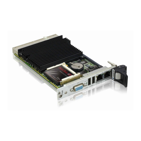
- Page 2 CP306 3U CompactPCI Pentium® M Based CPU Board Manual ID: 26799 Revision Index: 03 Issue Date: February 9, 2006 User Guide Artisan Technology Group - Quality Instrumentation ... Guaranteed | (888) 88-SOURCE | www.artisantg.com...
- Page 3 Internet web site: www.kontron.com Disclaimer Copyright © 2006 Kontron AG. All rights reserved. All data is for information purposes only and not guaranteed for legal purposes. Information has been carefully checked and is believed to be accurate; however, no responsibility is assumed for inaccuracies. Kontron and the Kontron logo and all other trademarks or registered trademarks are the property of their respective own- ers and are recognized.
-
Page 4: Table Of Contents
1.2.2 Board-Specific Information ............1 - 5 Optional Modules .................. 1 - 6 1.3.1 CP306-IDE1 Module ..............1 - 6 1.3.2 CP-RIO3-03 Rear I/O Module ............1 - 6 System Relevant Information ..............1 - 6 Board Diagrams ..................1 - 7 1.5.1... - Page 5 Preface CP306 Kontron Software Support ..............1 - 14 Standards .................... 1 - 15 Related Publications ................1 - 16 Chapter Functional Description ................2 - 3 CPU, Memory and Chipset ..............2 - 3 2.1.1 CPU ....................2 - 3 2.1.2...
- Page 6 Safety Requirements ................3 - 3 CP306 Initial Installation Procedures ............ 3 - 4 Standard Removal Procedures ............. 3 - 5 Hot Swap Procedures ................3 - 5 Installation of CP306 Peripheral Devices ..........3 - 5 3.5.1 CompactFlash Installation ............3 - 5 3.5.2 USB Device Installation ..............
- Page 7 The Menu Bar ................5 - 4 5.1.4 The Legend Bar ................5 - 5 Page vi © 2006 Kontron Modular Computers GmbH ID 26799, Rev. 03 Artisan Technology Group - Quality Instrumentation ... Guaranteed | (888) 88-SOURCE | www.artisantg.com...
- Page 8 Updating the Crisis Recovery Diskette ........5 - 43 5.9.4 Executing Phoenix Phlash16 ............5 - 43 ID 26799, Rev. 03 © 2006 Kontron Modular Computers GmbH Page vii Artisan Technology Group - Quality Instrumentation ... Guaranteed | (888) 88-SOURCE | www.artisantg.com...
- Page 9 Power Consumption Using Celeron® M and Real Applications ..6 - 9 6.5.4 Power Consumption Using Celeron® M and Testing Application 6 - 10 Power Consumption of CP306 Accessories ........6 - 11 Start-Up Current of the CP306 6 - 11 ..............
- Page 10 CP306-IDE1 ....................A - 3 Overview ....................A - 3 Technical Specifications ................ A - 3 CP306-IDE1 Module Functional Block Diagram ........A - 4 CP306-IDE1 Module Front Panel ............A - 5 CP306-IDE1 Module Layout ..............A - 6 A.5.1...
- Page 11 B.5.1.2 COM2 Configuration .............. B - 13 B.5.2 Shorting Chassis GND (Shield) to Logic GND ......B - 13 Page x © 2006 Kontron Modular Computers GmbH ID 26799, Rev. 03 Artisan Technology Group - Quality Instrumentation ... Guaranteed | (888) 88-SOURCE | www.artisantg.com...
- Page 12 Standards ....................1 - 15 Related Publications ................1 - 16 Supported Intel® Pentium® M Processors on the CP306 ....... 2 - 4 Maximum Power Dissipation of Intel® Pentium® M (CPU only) ....2 - 4 Intel® Pentium® M Core Voltage in the Various Frequency Modes ..2 - 4 Supported Intel®...
- Page 13 Power Consumption Win 2000 IDLE Mode Pentium® M ......6 - 7 Power Consumption Win 2000 100% CPU Usage Pentium® M ....6 - 7 Page xii © 2006 Kontron Modular Computers GmbH ID 26799, Rev. 03 Artisan Technology Group - Quality Instrumentation ... Guaranteed | (888) 88-SOURCE | www.artisantg.com...
- Page 14 6-14 Power Consumption Table for CP306 Accessories ....... 6 - 11 6-15 Start-Up Current of the CP306 with Pentium® M Processors ....6 - 11 6-16 Start-Up Current of the CP306 with Celeron® M Processors ....6 - 11 CP306-IDE1 Module Main Specifications ..........A - 3 Keyboard Connector CON6 Pinout ............
- Page 15 Preface CP306 This page has been intentionally left blank. Page xiv © 2006 Kontron Modular Computers GmbH ID 26799, Rev. 03 Artisan Technology Group - Quality Instrumentation ... Guaranteed | (888) 88-SOURCE | www.artisantg.com...
- Page 16 CP306 Functional Block Diagram ............1 - 7 CP306 4HP Front Panel ................1 - 8 CP306 Board Layout (Front View) ............1 - 9 CP306 Board Layout (Reverse View) ............1 - 9 855GME Chipset Functional Block Diagram ..........2 - 6 CompactFlash Socket Connector J8 .............
- Page 17 CP306IDE1 Module Functional Block Diagram ........A - 4 CP306-IDE1 Module Front Panel ............A - 5 CP306-IDE1 Module Layout (Front Side) ..........A - 6 CP306-IDE1 Module Layout (Reverse Side) ........... A - 6 Keyboard/Mouse Connector ..............A - 7 Adapter for Connecting Mouse/Keyboard via PS/2 .........
- Page 18 This document contains information proprietary to Kontron Modular Computers GmbH. It may not be copied or transmitted by any means, disclosed to others, or stored in any retrieval sys- tem or media without the prior written consent of Kontron Modular Computers GmbH or one of its authorized agents.
- Page 19 This symbol and title emphasize aspects the reader should read through carefully for his or her own advantage. Page xviii © 2006 Kontron Modular Computers GmbH ID 26799, Rev. 03 Artisan Technology Group - Quality Instrumentation ... Guaranteed | (888) 88-SOURCE | www.artisantg.com...
- Page 20 However, the life expectancy of your product can be drastically reduced by improper treatment during unpacking and installation. Therefore, in the interest of your own safety and of the correct operation of your new Kontron product, you are requested to conform with the following guidelines.
- Page 21 General Instructions on Usage • In order to maintain Kontron’s product warranty, this product must not be altered or mod- ified in any way. Changes or modifications to the device, which are not explicitly approved by Kontron Modular Computers GmbH and described in this manual or received from Kontron’s Technical Support as a special handling instruction, will void...
- Page 22 However, no other warran- YEAR LIMITED HARDWARE WARRANTY ties that may be granted or implied by anyone on behalf of Kontron are valid unless the con- sumer has the express written consent of Kontron Modular Computers GmbH.
- Page 23 Preface CP306 This page has been intentionally left blank. Page xxii © 2006 Kontron Modular Computers GmbH ID 26799, Rev. 03 Artisan Technology Group - Quality Instrumentation ... Guaranteed | (888) 88-SOURCE | www.artisantg.com...
- Page 24 CP306 Introduction Chapter Introduction ID 26799, Rev. 03 © 2006 Kontron Modular Computers GmbH Page 1 - 1 Artisan Technology Group - Quality Instrumentation ... Guaranteed | (888) 88-SOURCE | www.artisantg.com...
- Page 25 Introduction CP306 This page has been intentionally left blank. Page 1 - 2 © 2006 Kontron Modular Computers GmbH ID 26799, Rev. 03 Artisan Technology Group - Quality Instrumentation ... Guaranteed | (888) 88-SOURCE | www.artisantg.com...
-
Page 26: Introduction
• Information on the distinctive features of Kontron CompactPCI boards, such as functionality, hot swap capability. In addition, an overview is given for all existing Kontron CompactPCI boards with links to the relating data sheets. • Generic information on the Kontron CompactPCI backplanes, such as the slot... -
Page 27: Board Overview
The Pentium® M has the advantage of very low power consumption, whilst at the same time providing impressive processor speeds ranging from 1.1 GHz through 1.8 GHz with a Processor Side Bus (PSB) running at 400 MHz. The CP306 utilizes the Intel® 855GME and I/O Controller Hub 4 (ICH4) chipset. -
Page 28: Board-Specific Information
Introduction 1.2.2 Board-Specific Information The CP306 is a CompactPCI Pentium® M based single-board computer specifically designed for use in highly integrated platforms with solid mechanical interfacing for a wide range of industrial environment applications. Some of the CP306's outstanding features are: •... -
Page 29: System Relevant Information
1.3.2 CP-RIO3-03 Rear I/O Module Designed for use with a 32-bit rear I/O variant of the CP306 and a backplane with system slot rear I/O capability, this module provides rear I/O interfacing for two standard RS232 serial interfaces, one Fast Ethernet interface, two USB 2.0 interfaces, and the primary EIDE interface. -
Page 30: Cp306 Functional Block Diagram
CP306 Introduction Board Diagrams The following diagrams provide additional information concerning board functionality and component layout. 1.5.1 Functional Block Diagram Figure 1-1: CP306 Functional Block Diagram VGA-CRT Extension Temp. Reset Monitor Clock BIOS Flash Graphic Memory Power Mobile Controller Supply... -
Page 31: Cp306 4Hp Front Panel
Introduction CP306 1.5.2 Front Panel Figure 1-2: CP306 4HP Front Panel LEGEND: CP306: 4HP version CP 306 General Purpose LEDs • WD/GP (green): Watchdog or General Purpose; when lit during bootup, it indicates a PCI reset is active. • TH/GP (green): Overtemperature Status or General Purpose;... -
Page 32: Cp306 Board Layout (Front View)
CP306 Introduction 1.5.3 Board Layouts Figure 1-3: CP306 Board Layout (Front View) Firmware DC/DC Converter GMCH GP-LEDs IC10 Gigabit Ethernet 82541PI DDR RAM DC/DC Figure 1-4: CP306 Board Layout (Reverse View) C191 DC/DC IC22 IC23 Converter LOGIC ICH4 R294 C393... -
Page 33: Cp306 4Hp Version Main Specifications
Enhanced DMA controller, interrupt controller, and timer functions • Integrated IDE controller Ultra ATA/100/66/33 • USB 2.0 host interface with up to four USB ports available on the CP306 • One integrated LAN controller (82559 style) • System Management Bus (SMBus) compatible with most I²C™ devices •... - Page 34 • General purpose signals Hot Swap The CP306 supports the addition or removal of other boards whilst in a powered-up state. Individual clocks for each slot and Enum signal handling are in compliance with the PICMG 2.1 Hot Swa p Specification.
- Page 35 Introduction CP306 Table 1-2: CP306 4HP Version Main Specifications (Continued) CP306 SPECIFICATIONS Only available in conjunction with the CP306-IDE1 module ™ Multi-Mode Parallel Port • Standard Mode IBM PC/XT, PC/AT, and PS/2 compatible bi-directional parallel port • Standard flatcable pinout •...
- Page 36 CP306 Introduction Table 1-2: CP306 4HP Version Main Specifications (Continued) CP306 SPECIFICATIONS Mechanical 3U, 4HP, CompactPCI compliant form factor Power Consumption See Chapter 5 for details Temperature Range Operational: 0°C to +60°C Standard -25°C to +75°C E1 (optional; only with designated CPU types) -40°C to +85°C...
-
Page 37: Kontron Software Support
Technical Specifications table in Appendix A, CP306-IDE1 module. Kontron Software Support Kontron is one of the few CompactPCI and VME vendors providing inhouse support for most of the industry-proven real-time operating systems that are currently available. Due to its close... -
Page 38: Standards
CP306 Introduction Standards This Kontron Modular Computers’ product complies with the requirements of the following standards: Table 1-1: Standards TYPE ASPECT STANDARD REMARKS Emission EN55022 EN61000-6-3 Immission EN55024 EN61000-6-2 Electrical Safety EN60950-1 Mechanical Mechanical IEEE1101.10 Dimensions Environmental Vibration IEC60068-2-6 5g/10-300Hz/10... -
Page 39: Related Publications
PEP Modular Computers’ CompactPCI System Manual, ID 19954 CompactFlash Cards CF+ and CompactFlash Specification Revision 2.1 Page 1 - 16 © 2006 Kontron Modular Computers GmbH ID 26799, Rev. 03 Artisan Technology Group - Quality Instrumentation ... Guaranteed | (888) 88-SOURCE | www.artisantg.com... - Page 40 CP306 Functional Description Chapter Functional Description ID 26799, Rev. 03 © 2006 Kontron Modular Computers GmbH Page 2 - 1 Artisan Technology Group - Quality Instrumentation ... Guaranteed | (888) 88-SOURCE | www.artisantg.com...
- Page 41 Functional Description CP306 This page has been intentionally left blank. Page 2 - 2 © 2006 Kontron Modular Computers GmbH ID 26799, Rev. 03 Artisan Technology Group - Quality Instrumentation ... Guaranteed | (888) 88-SOURCE | www.artisantg.com...
-
Page 42: Functional Description
CPU, Memory and Chipset 2.1.1 The CP306 supports the latest Intel® Pentium® M processor family up to speeds of 1.8 GHz. The Intel® Pentium® M microprocessors offer exceptional performance with low power con- sumption. This processor is based on a new core which is optimized for low power consump- tion. -
Page 43: Supported Intel® Pentium® M Processors On The Cp306
Functional Description CP306 The following tables indicate the Intel® Pentium® M processors supported on the CP306, their maximum power dissipation and their core voltage in the various frequency modes. Table 2-1: Supported Intel® Pentium® M Processors on the CP306 SPEED 1.1 GHz... -
Page 44: Supported Intel® Celeron® M Processors On The Cp306
These processors always run with a fixed frequency. 2.1.2 Memory The CP306 has one bank of DDR333 (PC2700) memory, which has 256 MB, 512 MB or 1024 MB onboard soldered memory, and it also supports ECC. 2.1.3 855GME Chipset Overview The Intel®... -
Page 45: 855Gme Chipset Functional Block Diagram
ECC bits. The chipset supports DDR200, DDR266 and DDR333 (PC1600, PC2100 and PC2700) DDR SDRAM for system memory. The default memory speed for the CP306 is DDR333 (PC2700). 855GME Graphics Controller The 855GME includes a highly integrated graphics accelerator and H/W Motion Compensation engines for software MPEG2 decoding delivering high performance 3D and 2D video capabil- ities. -
Page 46: I/O Controller Hub Ich4
CMOS RAM. Features include an alarm function, programmable periodic interrupt and a 100-year calendar. All battery-backed CMOS RAM data remains stored in an additional EEPROM. This prevents data loss in case the CP306 is operated without battery. • Counter/Timer Three 8254-style counter/timers are included on the CP306 as defined for the PC/AT. -
Page 47: Battery
2.2.4 Reset The CP306 is automatically reset by a precision voltage monitoring circuit that detects a drop in voltage below the acceptable operating limit of 4.725 V for the 5 V line and below 3.0 V for the 3.3 V line, or in the event of a power failure of the DC/DC converter. Other reset sources include the watchdog timer and the optional local push-button switch. -
Page 48: Smbus Device Addresses
CP306 Functional Description 2.2.5 SMBus Devices The CP306 provides a System Management Bus (SMBus) for access to several system ² monitoring and configuration functions. The SMBus consists of a two-wire I C bus interface. The following table describes the function and address of every onboard SMBus device. -
Page 49: Compactflash Socket Connector J8
The following table provides the pinout for the CompactFlash Connector J8. Page 2 - 10 © 2006 Kontron Modular Computers GmbH ID 26799, Rev. 03 Artisan Technology Group - Quality Instrumentation ... Guaranteed | (888) 88-SOURCE | www.artisantg.com... -
Page 50: Compactflash Connector J8 Pinout
PCI bus can communicate while the other PCI bus is busy. ID 26799, Rev. 03 © 2006 Kontron Modular Computers GmbH Page 2 - 11 Artisan Technology Group - Quality Instrumentation ... Guaranteed | (888) 88-SOURCE | www.artisantg.com... -
Page 51: Board Interfaces
USB Interfaces The CP306 supports four USB 2.0 ports (two front I/O and two on the rear I/O). On the two rear I/O ports it is strongly recommended to use a cable below 3 metres in length for USB 2.0 devices. -
Page 52: Usb Connectors J4 And J5
CP306 Functional Description The CP306 has two USB interfaces implemented on a 4-pin connector with the following pinout: Table 2-9: USB Connectors J4 and J5 Pinout SIGNAL FUNCTION VCC signal UV0- Differential USB- UV0+ Differential USB+ GND signal Note ... -
Page 53: Partial List Of Display Modes Supported
2048 x 1536 2.3.3.3 CRT Interface and Connector J3 Figure 2-4: D-SUB CRT Connector J3 Page 2 - 14 © 2006 Kontron Modular Computers GmbH ID 26799, Rev. 03 Artisan Technology Group - Quality Instrumentation ... Guaranteed | (888) 88-SOURCE | www.artisantg.com... -
Page 54: Crt Connector J3 Pinout
CP306 Functional Description The 15-pin female connector J3 is used to connect a CRT monitor to the CP306 board. Table 2-11: CRT Connector J3 Pinout SIGNAL FUNCTION Red video signal output Green Green video signal output Blue Blue video signal output Hsync Horizontal sync. -
Page 55: Dual Fast Ethernet Connector J6
CP306 2.3.5 Ethernet The CP306 board includes one Fast Ethernet 10BASE-T/100BASE-TX port by Intel, ICH4 chipset, integrated LAN controller and one Gigabit 10Base-T/100Base-TX/1000Base-T Ether- net port based on the Intel® 82541PI Gigabit Ethernet PCI Bus Controller. Figure 2-5: Dual Fast Ethernet Connector J6... -
Page 56: Rj45 Connector J6-A Pinout
Functional Description 2.3.5.1 Fast Ethernet The CP306 board includes one 10Base-T/100Base-TX Ethernet port integrated within the ICH4 chipset (82559 style). The Boot from LAN feature is supported; for details please refer to section 5.5, BIOS Features Setup, in chapter 5, CMOS Setup. -
Page 57: Pinouts Of J6-B Based On The Implementation
BI_DB- BI_DB+ BI_DA+ BI_DC+ BI_DD+ BI_DC- BI_DD- BI_DB- BI_DA- BI_DD+ BI_DC+ BI_DD- BI_DC- Page 2 - 18 © 2006 Kontron Modular Computers GmbH ID 26799, Rev. 03 Artisan Technology Group - Quality Instrumentation ... Guaranteed | (888) 88-SOURCE | www.artisantg.com... -
Page 58: Eide Interface
UltraDMA / 100 slave device and the black connector to the UltraDMA / 100 master device. ID 26799, Rev. 03 © 2006 Kontron Modular Computers GmbH Page 2 - 19 Artisan Technology Group - Quality Instrumentation ... Guaranteed | (888) 88-SOURCE | www.artisantg.com... -
Page 59: J7 (Secondary Eide) Pinout
Address 2 HD select 0 HCS0 HCS1 HD select 1 LED driving Ground signal Page 2 - 20 © 2006 Kontron Modular Computers GmbH ID 26799, Rev. 03 Artisan Technology Group - Quality Instrumentation ... Guaranteed | (888) 88-SOURCE | www.artisantg.com... -
Page 60: Coding Key Colors
3.3 V and 5 V operation. Color coded keys prevent inadvertent installation of a 5 V peripheral board into a 3.3 V slot. The CP306 board may Z B D F A C E be ordered as either a 3.3 V or a 5 V version. -
Page 61: Compactpci Bus Connector J1 Pinout
Functional Description CP306 2.3.7.2 CompactPCI Connectors J1 and J2 Pinouts The CP306 is provided with two 2 mm x 2 mm pitch female CompactPCI bus connectors, J1 and J2. Table 2-17: CompactPCI Bus Connector J1 Pinout ROW A ROW B... -
Page 62: Bit Compactpci Bus Connector J2 Pinout
The 64-bit CompactPCI signals are not used on the board, but all 64 control signals are terminated to V(I/O). ID 26799, Rev. 03 © 2006 Kontron Modular Computers GmbH Page 2 - 23 Artisan Technology Group - Quality Instrumentation ... Guaranteed | (888) 88-SOURCE | www.artisantg.com... -
Page 63: Optional Rear I/O Interface On Compactpci Connector J2
CPU in the rack as there is practically no cabling on the CPU board. For the system rear I/O feature a special backplane is necessary. The CP306 with rear I/O is compatible with all standard CompactPCI passive backplanes with rear I/O support on the system slot. -
Page 64: Rear I/O Compactpci Bus Connector J2 Pinout
2.3.8.1 Optional Rear I/O Interface on CompactPCI Connector J2 The CP306 conducts a wide range of I/O signals through the rear I/O connector J2. Warning! To support the rear I/O feature a special backplane is necessary. Do not plug a rear I/O configured board in a non-system slot rear I/O backplane. - Page 65 * Note that this signal (BOUT) appears twice in the rear I/O CompactPCI bus connector J2 pinout in order to provide compatibility with the CP302. Pin number B11 refers to the CP306 and C13 refers to the CP302. The default configuration is CP306 (B11).
-
Page 66: Rear I/O Configuration
Extension Connectors J10 and J11 The I/O extension connectors provide cost-effective, flexible configuration options. ID 26799, Rev. 03 © 2006 Kontron Modular Computers GmbH Page 2 - 27 Artisan Technology Group - Quality Instrumentation ... Guaranteed | (888) 88-SOURCE | www.artisantg.com... -
Page 67: Extension Connectors J10 And J11
To support the three PCI master devices there are three sets of the following signals available: CLOCK, REQ and GNT. Page 2 - 28 © 2006 Kontron Modular Computers GmbH ID 26799, Rev. 03 Artisan Technology Group - Quality Instrumentation ... Guaranteed | (888) 88-SOURCE | www.artisantg.com... - Page 68 CP306 Installation Chapter Installation ID 26799, Rev. 03 © 2006 Kontron Modular Computers GmbH Page 3 - 1 Artisan Technology Group - Quality Instrumentation ... Guaranteed | (888) 88-SOURCE | www.artisantg.com...
- Page 69 Installation CP306 This page has been intentionally left blank. Page 3 - 2 © 2006 Kontron Modular Computers GmbH ID 26799, Rev. 03 Artisan Technology Group - Quality Instrumentation ... Guaranteed | (888) 88-SOURCE | www.artisantg.com...
-
Page 70: Installation
Installation Installation The CP306 has been designed for easy installation. However, the following standard precau- tions, installation procedures, and general information must be observed to ensure proper in- stallation and to preclude damage to the board, other system components, or injury to personnel. -
Page 71: Cp306 Initial Installation Procedures
Installation CP306 CP306 Initial Installation Procedures The following procedures are applicable only for the initial installation of the CP306 in a system. Procedures for standard removal and hot swap operations are found in their respective chap- ters. To perform an initial installation of the CP306 in a system proceed as follows: 1. -
Page 72: Standard Removal Procedures
7. Dispose of the board as required. Hot Swap Procedures The CP306 is designed for hot swap operation. When installed in the system slot, it is capable of supporting peripheral board hot swapping. In any event, hot swap is also a function of the application running on the CP306. -
Page 73: Usb Device Installation
Rear I/O Device Installation To ensure proper functioning of the rear I/O VGA interface, EIDE port and the Ethernet port, the solder jumpers on the CP306 must be configured for the rear I/O. See Chapter 4 for con- figuration details. -
Page 74: Software Installation
Plug and Play configuration rules. Note ... Due to the lead-free Ethernet controller used on the CP306, the installation of new software is required. Updated network drivers must be installed or included in preconfigured operating system images. - Page 75 Installation CP306 This page has been intentionally left blank. Page 3 - 8 © 2006 Kontron Modular Computers GmbH ID 26799, Rev. 03 Artisan Technology Group - Quality Instrumentation ... Guaranteed | (888) 88-SOURCE | www.artisantg.com...
- Page 76 CP306 Configuration Chapter Configuration ID 26799, Rev. 03 © 2006 Kontron Modular Computers GmbH Page 4 - 1 Artisan Technology Group - Quality Instrumentation ... Guaranteed | (888) 88-SOURCE | www.artisantg.com...
- Page 77 Configuration CP306 This page has been intentionally left blank. Page 4 - 2 © 2006 Kontron Modular Computers GmbH ID 26799, Rev. 03 Artisan Technology Group - Quality Instrumentation ... Guaranteed | (888) 88-SOURCE | www.artisantg.com...
-
Page 78: Compactflash Configuration
Closed zero ohm resistors The default setting is indicated by using italic bold. ID 26799, Rev. 03 © 2006 Kontron Modular Computers GmbH Page 4 - 3 Artisan Technology Group - Quality Instrumentation ... Guaranteed | (888) 88-SOURCE | www.artisantg.com... -
Page 79: Interrupt Setting
Configuration CP306 Interrupts The CP306 board uses the standard AT IRQ routing (8259 controller). This interrupt routing is the default, but can be modified via the BIOS. Table 4-4: Interrupt Setting PRIORITY STANDARD FUNCTION IRQ0 System Timer IRQ1 Keyboard Controller... -
Page 80: Pci Interrupt Routing
Free PIRQH Free USB 2.0 controller Memory Map The CP306 board uses the standard AT ISA memory map. 4.4.1 Memory Map for the 1st Megabyte The following table sets out the memory map for the first megabyte: Table 4-6: Memory Map for the 1st Megabyte... -
Page 81: I/O Address Map
Serial port COM3 3F0,3F7 Floppy Disk + Super-I/O #1 Com. 3F8,3FF Serial port COM1 Page 4 - 6 © 2006 Kontron Modular Computers GmbH ID 26799, Rev. 03 Artisan Technology Group - Quality Instrumentation ... Guaranteed | (888) 88-SOURCE | www.artisantg.com... -
Page 82: Special Registers Description
Configuration Special Registers Description The following registers are special registers which the CP306 uses to watch the onboard hardware special features and the CompactPCI control signals. Normally, only the system BIOS uses these registers, but they are documented here for application use as required. -
Page 83: Watchdog Timer
Once the watchdog timer is enabled it cannot be disabled except by resetting the system. Reserved Reserved Reserved Page 4 - 8 © 2006 Kontron Modular Computers GmbH ID 26799, Rev. 03 Artisan Technology Group - Quality Instrumentation ... Guaranteed | (888) 88-SOURCE | www.artisantg.com... -
Page 84: Watchdog, Compactpci Interrupt Configuration Register
Enable CPCI fail signal to NMI routing WNMI Disable Watchdog NMI routing Enable Watchdog NMI routing ID 26799, Rev. 03 © 2006 Kontron Modular Computers GmbH Page 4 - 9 Artisan Technology Group - Quality Instrumentation ... Guaranteed | (888) 88-SOURCE | www.artisantg.com... -
Page 85: I/O Status Register
Indicates that a Watchdog timeout has occurred Indicates that no Watchdog timeout has occurred Page 4 - 10 © 2006 Kontron Modular Computers GmbH ID 26799, Rev. 03 Artisan Technology Group - Quality Instrumentation ... Guaranteed | (888) 88-SOURCE | www.artisantg.com... -
Page 86: I/O Configuration Register
Enable LED1 for GP DBIOS Default boot from onboard FWH Boot from IDE module FWH Reserved ID 26799, Rev. 03 © 2006 Kontron Modular Computers GmbH Page 4 - 11 Artisan Technology Group - Quality Instrumentation ... Guaranteed | (888) 88-SOURCE | www.artisantg.com... -
Page 87: Board Id Register
Configuration CP306 4.5.7 Board Version This register describes the hardware and the board version. The content of this register is unique for each Kontron CompactPCI board. Table 4-12: Board ID Register REGISTER NAME Board Version ACCESS ADDRESS 0x288 BIT POSITION... -
Page 88: Led Control Register
LED on LED1 LED off (TH/GP) LED on Reserved Reserved Reserved Reserved Reserved Reserved ID 26799, Rev. 03 © 2006 Kontron Modular Computers GmbH Page 4 - 13 Artisan Technology Group - Quality Instrumentation ... Guaranteed | (888) 88-SOURCE | www.artisantg.com... - Page 89 Configuration CP306 This page has been intentionally left blank. Page 4 - 14 © 2006 Kontron Modular Computers GmbH ID 26799, Rev. 03 Artisan Technology Group - Quality Instrumentation ... Guaranteed | (888) 88-SOURCE | www.artisantg.com...
- Page 90 CP306 Phoenix BIOS Chapter Chapter Phoenix BIOS Phoenix BIOS ID 26799, Rev. 03 © 2006 Kontron Modular Computers GmbH Page 5 - 1 Artisan Technology Group - Quality Instrumentation ... Guaranteed | (888) 88-SOURCE | www.artisantg.com...
- Page 91 Phoenix BIOS CP306 This page has been intentionally left blank. Page 5 - 2 © 2006 Kontron Modular Computers GmbH ID 26799, Rev. 03 Artisan Technology Group - Quality Instrumentation ... Guaranteed | (888) 88-SOURCE | www.artisantg.com...
-
Page 92: Phoenix Bios
Setup. Note ... There are two different versions of the BIOS, one for the 4HP CP306 and one for the 8HP. Care should be taken when downloading BIOS upgrades to download the correct version for the board in use. -
Page 93: The Menu Bar
Boot sequence configuration OEMFeatures Configuration of special board features Exit Exits the current menu Page 5 - 4 © 2006 Kontron Modular Computers GmbH ID 26799, Rev. 03 Artisan Technology Group - Quality Instrumentation ... Guaranteed | (888) 88-SOURCE | www.artisantg.com... -
Page 94: The Legend Bar
To display a sub-menu, use the arrow keys to move the cursor to the sub-menu you want. Then press <Enter>. A pointer marks all sub-menus. ID 26799, Rev. 03 © 2006 Kontron Modular Computers GmbH Page 5 - 5 Artisan Technology Group - Quality Instrumentation ... Guaranteed | (888) 88-SOURCE | www.artisantg.com... -
Page 95: The Field Help Window
<End> displays the first and last page. Pressing <Enter> displays each page and then exits the window. Press <Esc> to exit the current window. Page 5 - 6 © 2006 Kontron Modular Computers GmbH ID 26799, Rev. 03 Artisan Technology Group - Quality Instrumentation ... Guaranteed | (888) 88-SOURCE | www.artisantg.com... -
Page 96: Main Menu Selections
ATA interface to a host, it is recommended that the host and the device be placed at the two ends of the cable. ID 26799, Rev. 03 © 2006 Kontron Modular Computers GmbH Page 5 - 7 Artisan Technology Group - Quality Instrumentation ... Guaranteed | (888) 88-SOURCE | www.artisantg.com... -
Page 97: Master/Slave Sub-Menu - Screen Display
Use the legend keys listed on the bottom to make your selections and exit to the Main Menu. Use the following chart to configure the hard disk. Page 5 - 8 © 2006 Kontron Modular Computers GmbH ID 26799, Rev. 03 Artisan Technology Group - Quality Instrumentation ... Guaranteed | (888) 88-SOURCE | www.artisantg.com... -
Page 98: Master/Slave Sub-Menu Options
User type selected. You can find the correct parameters for hard-disk drives in the drive manual or written on the casing of the drive itself. ID 26799, Rev. 03 © 2006 Kontron Modular Computers GmbH Page 5 - 9 Artisan Technology Group - Quality Instrumentation ... Guaranteed | (888) 88-SOURCE | www.artisantg.com... -
Page 99: Advanced Menu - Screen Display
Incorrect settings can cause your system to malfunction. To correct mistakes, return to Setup and restore the Setup Defaults with <F9>. Page 5 - 10 © 2006 Kontron Modular Computers GmbH ID 26799, Rev. 03 Artisan Technology Group - Quality Instrumentation ... Guaranteed | (888) 88-SOURCE | www.artisantg.com... -
Page 100: Advanced Chipset Control Options
UMA = 8 MB Graphics Device will use. UMA = 16 MB UMA = 32 MB ID 26799, Rev. 03 © 2006 Kontron Modular Computers GmbH Page 5 - 11 Artisan Technology Group - Quality Instrumentation ... Guaranteed | (888) 88-SOURCE | www.artisantg.com... -
Page 101: Pci/Pnp Configuration Options
BIOS. Page 5 - 12 © 2006 Kontron Modular Computers GmbH ID 26799, Rev. 03 Artisan Technology Group - Quality Instrumentation ... Guaranteed | (888) 88-SOURCE | www.artisantg.com... -
Page 102: Pci/Pnp Isa Irq Resource Exclusion Options
IRQ9 is used for SCI in ACPI mode. Do not use IRQ9 for legacy ISA devices. ID 26799, Rev. 03 © 2006 Kontron Modular Computers GmbH Page 5 - 13 Artisan Technology Group - Quality Instrumentation ... Guaranteed | (888) 88-SOURCE | www.artisantg.com... -
Page 103: Memory Cache - Screen Display
Use the legend keys listed on the bottom to make your selections and exit to the Main Menu. Use this chart to configure the memory cache. Page 5 - 14 © 2006 Kontron Modular Computers GmbH ID 26799, Rev. 03 Artisan Technology Group - Quality Instrumentation ... Guaranteed | (888) 88-SOURCE | www.artisantg.com... -
Page 104: Memory Cache Configuration Options
Incorrect settings can cause your system to malfunction. To correct mistakes, return to Setup and restore the Setup Defaults with <F9>. ID 26799, Rev. 03 © 2006 Kontron Modular Computers GmbH Page 5 - 15 Artisan Technology Group - Quality Instrumentation ... Guaranteed | (888) 88-SOURCE | www.artisantg.com... -
Page 105: I/O Device Configuration Menu 4 Hp Version - Screen Display
The Serial Ports A and B are only present in conjunction with the onboard UART. Page 5 - 16 © 2006 Kontron Modular Computers GmbH ID 26799, Rev. 03 Artisan Technology Group - Quality Instrumentation ... Guaranteed | (888) 88-SOURCE | www.artisantg.com... -
Page 106: I/O Device Configuration Options 4 Hp Version
* Indicates a DMA, Interrupt, I/O, or memory resource conflict with another de- vice. Resolve the conflict by selecting another settings for the devices. ID 26799, Rev. 03 © 2006 Kontron Modular Computers GmbH Page 5 - 17 Artisan Technology Group - Quality Instrumentation ... Guaranteed | (888) 88-SOURCE | www.artisantg.com... -
Page 107: I/O Device Configuration Menu 8 Hp Version - Screen Display
-/+ Change Values ESC Exit Select Menu Enter Select Sub-Menu F10 Save and Exit Page 5 - 18 © 2006 Kontron Modular Computers GmbH ID 26799, Rev. 03 Artisan Technology Group - Quality Instrumentation ... Guaranteed | (888) 88-SOURCE | www.artisantg.com... -
Page 108: I/O Device Configuration Options 8 Hp Version
Primary for one diskette drive installed, or Secondary for two diskette drives installed. ID 26799, Rev. 03 © 2006 Kontron Modular Computers GmbH Page 5 - 19 Artisan Technology Group - Quality Instrumentation ... Guaranteed | (888) 88-SOURCE | www.artisantg.com... - Page 109 * Indicates a DMA, Interrupt, I/O, or memory resource conflict with another de- vice. Resolve the conflict by selecting another settings for the devices. Page 5 - 20 © 2006 Kontron Modular Computers GmbH ID 26799, Rev. 03 Artisan Technology Group - Quality Instrumentation ... Guaranteed | (888) 88-SOURCE | www.artisantg.com...
-
Page 110: Keyboard Features Options
Set the delay time after the key is held down before it delay 1/2 sec begins to repeat the keystroke. 3/4 sec 1 sec ID 26799, Rev. 03 © 2006 Kontron Modular Computers GmbH Page 5 - 21 Artisan Technology Group - Quality Instrumentation ... Guaranteed | (888) 88-SOURCE | www.artisantg.com... -
Page 111: Miscellaneous Options
Large Disk is one that has more than 1024 cylinders, more than 16 heads or more than 63 sectors per track. Page 5 - 22 © 2006 Kontron Modular Computers GmbH ID 26799, Rev. 03 Artisan Technology Group - Quality Instrumentation ... Guaranteed | (888) 88-SOURCE | www.artisantg.com... -
Page 112: Security Menu Options
If supervisor password is set and this option is disabled, BIOS assumes user is booting. ID 26799, Rev. 03 © 2006 Kontron Modular Computers GmbH Page 5 - 23 Artisan Technology Group - Quality Instrumentation ... Guaranteed | (888) 88-SOURCE | www.artisantg.com... -
Page 113: Power Menu Options
Windows XP. A fresh installation of the OS must also occur when the APIC Mode is desired. Page 5 - 24 © 2006 Kontron Modular Computers GmbH ID 26799, Rev. 03 Artisan Technology Group - Quality Instrumentation ... Guaranteed | (888) 88-SOURCE | www.artisantg.com... -
Page 114: Boot Menu - Screen Display
Lan-Boot is based on Etherboot 5.1.6, a LAN-Boot implementation, which is covered by the GNU public license. It has been adopted for use with Kontron CompactPCI Hardware. As re- quired by the GNU public license, the complete source code and further information are avail- able via the internet (www.sourceforge.net). - Page 115 The Boot Menu shows two lists, the boot priority list and the exclude from boot order list. Page 5 - 26 © 2006 Kontron Modular Computers GmbH ID 26799, Rev. 03 Artisan Technology Group - Quality Instrumentation ... Guaranteed | (888) 88-SOURCE | www.artisantg.com...
-
Page 116: Oem Features Menu - Screen Display
Use the legend keys to make your selections and exit to the Main Menu. Use the following chart in making your selections: ID 26799, Rev. 03 © 2006 Kontron Modular Computers GmbH Page 5 - 27 Artisan Technology Group - Quality Instrumentation ... Guaranteed | (888) 88-SOURCE | www.artisantg.com... -
Page 117: Oem Features Options
For saving space in the ROM area. Select No: JRC extension will not be loaded. Page 5 - 28 © 2006 Kontron Modular Computers GmbH ID 26799, Rev. 03 Artisan Technology Group - Quality Instrumentation ... Guaranteed | (888) 88-SOURCE | www.artisantg.com... -
Page 118: Speedstep Frequency Table
Setup Defaults ESC Exit Select Menu Enter Select Sub-Menu F10 Save and Exit ID 26799, Rev. 03 © 2006 Kontron Modular Computers GmbH Page 5 - 29 Artisan Technology Group - Quality Instrumentation ... Guaranteed | (888) 88-SOURCE | www.artisantg.com... -
Page 119: Watchdog Settings - Screen Display
Setup Defaults ESC Exit Select Menu Enter Select Sub-Menu F10 Save and Exit Page 5 - 30 © 2006 Kontron Modular Computers GmbH ID 26799, Rev. 03 Artisan Technology Group - Quality Instrumentation ... Guaranteed | (888) 88-SOURCE | www.artisantg.com... -
Page 120: Watchdog Settings Options
Fail signal from the power supply. If this signal is to used inside an application, it may be routed to NMI here. ID 26799, Rev. 03 © 2006 Kontron Modular Computers GmbH Page 5 - 31 Artisan Technology Group - Quality Instrumentation ... Guaranteed | (888) 88-SOURCE | www.artisantg.com... -
Page 121: Temperature Management Options
P4 Term Trip Shows the P4 max Temperature Page 5 - 32 © 2006 Kontron Modular Computers GmbH ID 26799, Rev. 03 Artisan Technology Group - Quality Instrumentation ... Guaranteed | (888) 88-SOURCE | www.artisantg.com... -
Page 122: Front-Rear I/O Options
This is a display only field, which indicates whether the board is Rear I/O configured. ID 26799, Rev. 03 © 2006 Kontron Modular Computers GmbH Page 5 - 33 Artisan Technology Group - Quality Instrumentation ... Guaranteed | (888) 88-SOURCE | www.artisantg.com... -
Page 123: System Info Options
It shows the index of the onboard logic. Serial Number This is a display only field. The serial number is unique to each board produced by Kontron. It could be used also by the cus- tomer to identify specific boards. Page 5 - 34 ©... -
Page 124: Exit Menu - Screen Display
Use this option to exit Setup without storing in CMOS any new selections you may have made. The selections previously in effect remain in effect. ID 26799, Rev. 03 © 2006 Kontron Modular Computers GmbH Page 5 - 35 Artisan Technology Group - Quality Instrumentation ... Guaranteed | (888) 88-SOURCE | www.artisantg.com... -
Page 125: Load Setup Defaults
Selecting “Save Changes” saves all the selections without exiting Setup. You can return to the other menus if you want to review and change your selections. Page 5 - 36 © 2006 Kontron Modular Computers GmbH ID 26799, Rev. 03 Artisan Technology Group - Quality Instrumentation ... Guaranteed | (888) 88-SOURCE | www.artisantg.com... -
Page 126: Phoenixbios Messages
The CMOS clock battery indicator shows the battery is dead. Replace the battery and run Set- up to reconfigure the system. ID 26799, Rev. 03 © 2006 Kontron Modular Computers GmbH Page 5 - 37 Artisan Technology Group - Quality Instrumentation ... Guaranteed | (888) 88-SOURCE | www.artisantg.com... - Page 127 02B3 Incorrect Drive B type - run SETUP Type of floppy drive B: not correctly identified in Setup. Page 5 - 38 © 2006 Kontron Modular Computers GmbH ID 26799, Rev. 03 Artisan Technology Group - Quality Instrumentation ... Guaranteed | (888) 88-SOURCE | www.artisantg.com...
- Page 128 System, Extended, or Shadow memory. Fixed Disk n Fixed disk n (0-3) identified. ID 26799, Rev. 03 © 2006 Kontron Modular Computers GmbH Page 5 - 39 Artisan Technology Group - Quality Instrumentation ... Guaranteed | (888) 88-SOURCE | www.artisantg.com...
- Page 129 Parity error found in the I/O bus. BIOS attempts to locate the address and display it on the screen. If it cannot locate the address, it displays ????. Page 5 - 40 © 2006 Kontron Modular Computers GmbH ID 26799, Rev. 03 Artisan Technology Group - Quality Instrumentation ... Guaranteed | (888) 88-SOURCE | www.artisantg.com...
- Page 130 BIOS which can be reclaimed by a virtual memory manager. Video BIOS shadowed Video BIOS successfully copied to shadow RAM. ID 26799, Rev. 03 © 2006 Kontron Modular Computers GmbH Page 5 - 41 Artisan Technology Group - Quality Instrumentation ... Guaranteed | (888) 88-SOURCE | www.artisantg.com...
-
Page 131: Phoenix Phlash16
MINIDOS.SYS must occupy the first directory entry for the diskette to boot properly. Page 5 - 42 © 2006 Kontron Modular Computers GmbH ID 26799, Rev. 03 Artisan Technology Group - Quality Instrumentation ... Guaranteed | (888) 88-SOURCE | www.artisantg.com... -
Page 132: Updating The Crisis Recovery Diskette
One consists of pressing the <F5> key (only if you are using DOS 5.0 or above), and the other requires the creation of a boot diskette. ID 26799, Rev. 03 © 2006 Kontron Modular Computers GmbH Page 5 - 43 Artisan Technology Group - Quality Instrumentation ... Guaranteed | (888) 88-SOURCE | www.artisantg.com... - Page 133 See 5.8.2 on page 5-40 for details about creating the Crisis Recovery Diskette. Page 5 - 44 © 2006 Kontron Modular Computers GmbH ID 26799, Rev. 03 Artisan Technology Group - Quality Instrumentation ... Guaranteed | (888) 88-SOURCE | www.artisantg.com...
-
Page 134: Com Ports Pinout
• you can exit the server mode by pressing both control keys on the keyboard simulta- neously. ID 26799, Rev. 03 © 2006 Kontron Modular Computers GmbH Page 5 - 45 Artisan Technology Group - Quality Instrumentation ... Guaranteed | (888) 88-SOURCE | www.artisantg.com... -
Page 135: Post Errors And Beep Codes
BIOS can process the error, the value displayed at the port 80h is the last test performed. In this case, the screen does not display the error code. Page 5 - 46 © 2006 Kontron Modular Computers GmbH ID 26799, Rev. 03 Artisan Technology Group - Quality Instrumentation ... Guaranteed | (888) 88-SOURCE | www.artisantg.com... -
Page 136: Checkpoint And Beep Codes
RAM failure on address line xxxx* 1-3-4-3 RAM failure on data bits xxxx* of low byte of memory ID 26799, Rev. 03 © 2006 Kontron Modular Computers GmbH Page 5 - 47 Artisan Technology Group - Quality Instrumentation ... Guaranteed | (888) 88-SOURCE | www.artisantg.com... - Page 137 Test RAM between 512 and 640 kB Test extended memory Test extended memory address lines Jump to UserPatch1 Page 5 - 48 © 2006 Kontron Modular Computers GmbH ID 26799, Rev. 03 Artisan Technology Group - Quality Instrumentation ... Guaranteed | (888) 88-SOURCE | www.artisantg.com...
- Page 138 Jump to UserPatch2 Build MPTABLE for multi-processor boards Install CD ROM for boot ID 26799, Rev. 03 © 2006 Kontron Modular Computers GmbH Page 5 - 49 Artisan Technology Group - Quality Instrumentation ... Guaranteed | (888) 88-SOURCE | www.artisantg.com...
- Page 139 Try to boot with INT 19 Initialize POST Error Manager (PEM) Initialize error logging Page 5 - 50 © 2006 Kontron Modular Computers GmbH ID 26799, Rev. 03 Artisan Technology Group - Quality Instrumentation ... Guaranteed | (888) 88-SOURCE | www.artisantg.com...
- Page 140 Shadow Boot Block System memory test Initialize interrupt vectors Initialize Run Time Clock Initialize video ID 26799, Rev. 03 © 2006 Kontron Modular Computers GmbH Page 5 - 51 Artisan Technology Group - Quality Instrumentation ... Guaranteed | (888) 88-SOURCE | www.artisantg.com...
- Page 141 It repeats this sequence continuously. Page 5 - 52 © 2006 Kontron Modular Computers GmbH ID 26799, Rev. 03 Artisan Technology Group - Quality Instrumentation ... Guaranteed | (888) 88-SOURCE | www.artisantg.com...
- Page 142 CP306 Power Considerations Chapter Power Considerations ID 26799, Rev. 03 © 2006 Kontron Modular Computers GmbH Page 6 - 1 Artisan Technology Group - Quality Instrumentation ... Guaranteed | (888) 88-SOURCE | www.artisantg.com...
- Page 143 Power Considerations CP306 This page has been intentionally left blank. Page 6 - 2 © 2006 Kontron Modular Computers GmbH ID 26799, Rev. 03 Artisan Technology Group - Quality Instrumentation ... Guaranteed | (888) 88-SOURCE | www.artisantg.com...
-
Page 144: Absolute Maximum Ratings
Failure to comply with the above may result in damage to your board. The following table specifies the ranges for the different input power voltages within which the board is functional. The CP306 is not guaranteed to function if the board is not operated within the prescribed limits. Table 6-2:... -
Page 145: Backplane Requirements
6.4.1 Voltage Ramp Power supplies must comply with the following guidelines, in order to be used with the CP306. • Beginning at 10% of the nominal output voltage, the voltage must rise within > 0.1 ms to < 20 ms to the specified regulation range of the voltage. Typically: >... -
Page 146: Input Voltage Characteristics
Power Considerations 6.4.3 Rise Time Diagram The following figure illustrates an example of the recommended voltage ramp of a CompactPCI power supply for all Kontron boards delivered up to now. Figure 6-1: Voltage Ramp of the CP3-SVE180 AC Power Supply 6.4.4 Recommended Operating Conditions The tolerance of the voltage lines is described in the CompactPCI specification (PICMG 2.0... -
Page 147: Supply Voltage Regulation
When a PSU of this type is used, it will not power up correctly and the CP306 may hang up. The solution is to use an industrial PSU or to add more load to the system. -
Page 148: Power Consumption Bios Pentium® M
3.3 V Total 12.15 W 17.4 W 15.9 W 28.25 W 27.2 W ID 26799, Rev. 03 © 2006 Kontron Modular Computers GmbH Page 6 - 7 Artisan Technology Group - Quality Instrumentation ... Guaranteed | (888) 88-SOURCE | www.artisantg.com... -
Page 149: Power Consumption Win 2000 High Power Tool Pentium® M
The values in the above table are measured using the Intel® High Power Tool. This tool serves only for checking the onboard power supplies and does not represent the power consumption of the CP306 during normal operation. In normal software applications this maximum power consumption level will never be reached. -
Page 150: Power Consumption Bios Celeron® M
1.366 V 3.15 W 12.5 W 3.3 V Total 12.2 W 21.5 W ID 26799, Rev. 03 © 2006 Kontron Modular Computers GmbH Page 6 - 9 Artisan Technology Group - Quality Instrumentation ... Guaranteed | (888) 88-SOURCE | www.artisantg.com... -
Page 151: Power Consumption Win 2000 High Power Tool Celeron® M
The values in the above table are measured using the Intel® High Power Tool. This tool serves only for checking the onboard power supplies and does not represent the power consumption of the CP306 during normal operation. In normal software applications this maximum power consumption level will never be reached. -
Page 152: Power Consumption Table For Cp306 Accessories
100 mW Start-Up Current of the CP306 The following tables indicate the start-up current of the CP306 during the first 2-3 seconds after the power supply has been switched on. The power consumption of the CP306 during opera- tion is indicated in tables 6-4 to 6-7 and 6-9 to 6-12. - Page 153 Power Considerations CP306 This page has been intentionally left blank. Page 6 - 12 © 2006 Kontron Modular Computers GmbH ID 26799, Rev. 03 Artisan Technology Group - Quality Instrumentation ... Guaranteed | (888) 88-SOURCE | www.artisantg.com...
- Page 154 CP306 System Considerations Chapter System Considerations ID 26799, Rev. 03 © 2006 Kontron Modular Computers GmbH Page 7 - 1 Artisan Technology Group - Quality Instrumentation ... Guaranteed | (888) 88-SOURCE | www.artisantg.com...
- Page 155 System Considerations CP306 This page has been intentionally left blank. Page 7 - 2 © 2006 Kontron Modular Computers GmbH ID 26799, Rev. 03 Artisan Technology Group - Quality Instrumentation ... Guaranteed | (888) 88-SOURCE | www.artisantg.com...
-
Page 156: System Considerations
7.1.1 Passive Thermal Regulation The thermal management architecture implemented on the CP306 can be described as being three separate but related functions. The goal of all three functions is to protect the processor and reduce processor power consumption. Enabling the thermal control circuit allows the pro- cessor to maintain a safe operating temperature without the need for special software drivers or interrupt handling routines. -
Page 157: Cpu External Thermal Supervision
125°C. Upon assertion of Thermtrip, the processor will shut off its internal clocks (thus halting program execution) in an attempt to reduce the processor junction temperature. Once activated, Thermtrip remains latched until the CP306 undergoes a cold restart is per- formed (all power off and then on again). -
Page 158: Thermal Management Recommendations
7.1.2.1 Heat Sinks The CP306 is fitted with an optimally designed heat sink. The physical size, shape, and con- struction ensures the best possible thermal resistance (R ) coefficients. In addition, it is spe- cifically designed to efficiently support forced air flow concepts as found in a modern CompactPCI system chassis. -
Page 159: Mobile Pentium® M Temperature Vs. Airspeed Graph
7.1.2.2 Forced Air Flow When developing applications using the CP306, the system integrator must be aware of the overall system thermal requirements. System chassis must be provided which satisfy these re- quirements. As an aid to the system integrator, a processor characteristics graph is provided for the Pentium®... -
Page 160: Mobile Celeron® M Temperature Vs. Airspeed Graph
An airflow of 1.0 m/s is a typical value for a standard Kontron ASM rack (3U CompactPCI rack with a 1U cooling fan tray). Newer ASMs from Kontron will have an airspeed of 2.0 m/s or more. For other racks or housings the available airflow will differ. The maximum ambient operating temperature must be recalculated and/or measured for such environments. -
Page 161: Peripherals
When determining the themal requirements for a given application, peripherals to be used with the CP306 must also be considered. Devices such as hard disks, PMC modules, etc. which are directly attached to the CP306 must also be capable of being operated at the temperatures foreseen for the application. - Page 162 CP306 CP306-IDE1 Appendix CP306-IDE1 ID 26799, Rev. 03 © 2006 Kontron Modular Computers GmbH Page A - 1 Artisan Technology Group - Quality Instrumentation ... Guaranteed | (888) 88-SOURCE | www.artisantg.com...
- Page 163 CP306-IDE1 CP306 This page has been intentionally left blank. Page A - 2 © 2006 Kontron Modular Computers GmbH ID 26799, Rev. 03 Artisan Technology Group - Quality Instrumentation ... Guaranteed | (888) 88-SOURCE | www.artisantg.com...
-
Page 164: Cp306-Ide1 Module Main Specifications
The module connects to the CP306 across an I/O extension connector. The I/O extension connector provides the possibility to mount several Low Pin Count (LPC) devices to the CP306 for adding additional functionality which is not provided on the CP306 main board. -
Page 165: Cp306Ide1 Module Functional Block Diagram
CP306-IDE1 CP306 CP306-IDE1 Module Functional Block Diagram Figure A-1: CP306IDE1 Module Functional Block Diagram I/O Extension EIDE Interfaces Onboard 2.5” Super Floppy LPT1 EIDE Keyboard 40-pin COM2 COM1 Mouse 9-pin D-sub 9-pin D-sub PS/2 = on Board = on Front Panel Page A - 4 ©... -
Page 166: Cp306-Ide1 Module Front Panel
CP306 CP306-IDE1 CP306-IDE1 Module Front Panel Figure A-2: CP306-IDE1 Module Front Panel LEGEND: CP 306 General Purpose LEDs • WD/GP (green): Watchdog or General Purpose • TH/GP (green): Overtemperature Status or General Purpose • HDD (green): Monitors hard disk activity Reset Button •... -
Page 167: Cp306-Ide1 Module Layout (Front Side)
CP306 CP306-IDE1 Module Layout The transition module includes additional standard PC interfaces, two configurable COM ports and one ECP/EPP compatible Parallel Port. A.5.1 CP306-IDE1 Module Layout Figure A-3: CP306-IDE1 Module Layout (Front Side) LED & RESET CON1 CON2 CON5 CON7... -
Page 168: Keyboard/Mouse Connector
Mini-DIN connector. The keyboard power supply unit is protected by a 500 mA fuse. All signal lines are EMI-filtered. A special adapter to connect a mouse device and/or a keyboard to the PS/2 connector ia available from Kontron Figure A-6: Adapter for Connecting Mouse/Keyboard via PS/2 6-pin Mini-Din,... -
Page 169: Keyboard Connector Con6 Pinout
CP306-IDE1 CP306 A.6.1.1 Keyboard Connector CON6 Pinout The CP306 has the AT keyboard connector implemented on a 6-pin Mini-Din connector. Table A-2: Keyboard Connector CON6 Pinout SIGNAL DESCRIPTION KDATA Keyboard data MDATA Mouse data Ground signal VCC signal KCLK Keyboard clock... -
Page 170: Serial Port Connectors Con2 And Con5 Pinouts
The COM1 interface is routed to the connector CON2 and the COM2 interface is routed to CON5. Note ... The RS422 connector is Kontron-specific and the serial control signals are not available. Table A-3: Serial Port Connectors CON2 and CON5 Pinouts... -
Page 171: Serial Port Configuration Diagram
D-sub A.6.3 Parallel Port Interface The CP306-IDE1 module is provided with an IEEE1284, ECP/EPP-compatible parallel port/printer interface. The parallel port is a 26-pin 2.54mm connector. To use a standard parallel port device a special adapter is necessary. Page A - 10 ©... -
Page 172: Pc-Compatible Parallel Interface Connector Con1
CP306 CP306-IDE1 Figure A-9: PC-Compatible Parallel Interface Connector CON1 ID 26799, Rev. 03 © 2006 Kontron Modular Computers GmbH Page A - 11 Artisan Technology Group - Quality Instrumentation ... Guaranteed | (888) 88-SOURCE | www.artisantg.com... -
Page 173: A.6.3.1 Parallel Port Connector Con1 Pinout
The EIDE interface on the CP306-IDE1 module comprises three connectors, CON3, CON4 and CON9. The CON9 connector, situated on the reverse of the board, is used to connect the CP306-IDE1 module to the baseboard, while the other two connectors, CON3 and CON4, are used to connect devices to the CP306-IDE1 module. - Page 174 Figure A-10:Front Side EIDE Interface Connectors CON3 and CON4 CON3 CON4 Figure A-11:Rear Side EIDE Interface Connector CON9 CON9 ID 26799, Rev. 03 © 2006 Kontron Modular Computers GmbH Page A - 13 Artisan Technology Group - Quality Instrumentation ... Guaranteed | (888) 88-SOURCE | www.artisantg.com...
- Page 175 Up to two devices (which must be master/slave pairs) may be attached to the CP306-IDE1 board; either both devices on CON3 or on CON4 or one device on each connector. The maximum length of cable that may be used for CON4 is 25 cm.
-
Page 176: Pinout Of The At 44-Pin Connector
CP306 CP306-IDE1 A.6.4.1 Onboard EIDE Connector CON4 Pinout A 2.5” hard disk or Flash disk may be mounted directly onto the CP306-IDE1 module using the 44-pin connector CON4. Table A-5: Pinout of the AT 44-Pin Connector DESCRIPTION SIGNAL SIGNAL DESCRIPTION... -
Page 177: Pinouts Of Eide Connectors Con3 And Con9
A.6.4.2 EIDE Connectors CON3 and CON9 Pinouts A wide range of EIDE devices may be connected to the CP306-IDE1 module at CON3 using a ribbon cable. The following table describes the pinouts of connectors CON3 and CON9, which are identical, with the corresponding signal names. -
Page 178: Floppy Drive Interface Connector Con7
CP306 CP306-IDE1 A.6.5 Floppy Drive Interface The floppy drive interface CON7 of the CP306-IDE1 module is realized as a 34-pin, 2.54-mm pitch pin row connector. Figure A-12: Floppy Drive Interface Connector CON7 Warning! If the floppy drive connection cable is inverted (pin “1” in place of pin “34”) at “power on”, the floppy drive will work uninterruptedly with consequent risk of... -
Page 179: Floppy Drive Connector Con7 Pinout
Write protect RDDATA Read data HEADSEL Head select DSKCHG Disk change Ground signal NUMBERS. Page A - 18 © 2006 Kontron Modular Computers GmbH ID 26799, Rev. 03 Artisan Technology Group - Quality Instrumentation ... Guaranteed | (888) 88-SOURCE | www.artisantg.com... -
Page 180: I/O Extension Interface Connector Con10
CP306 CP306-IDE1 A.6.6 I/O Extension Interface Connector CON10 The I/O interface connector CON10 provides all the necessary signals for the CP306-IDE1 module. Figure A-13:I/O Extension Interface Connector CON10 A.6.7 Speaker Connector J3 This 2-pin connector enables connection to an external speaker. -
Page 181: Shorting Chassis Gnd (Shield) To Logic Gnd
The default setting is indicated by using italic bold. A.7.2 Serial Port Setting The serial interfaces CON2 (COM1) and CON5 (COM2) on the CP306-IDE1 module may be configured for either RS232, RS422 or RS485 by setting solder jumpers. Table A-9: Jumper Setting to Configure COM1... -
Page 182: Jumper Settings For Rs422 Rxd Termination (Com1)
A.7.2.1 RS422 and RS485 COM1 Termination When the CP306-IDE1 module is using the onboard RS485 interface and is the last on the RS422 or RS485 bus, then the RS422 or RS485 interface must provide termination resistance. The purpose of jumpers J6 and J7 are to enable this line termination resistor (120 R). - Page 183 CP306-IDE1 CP306 This page has been intentionally left blank. Page A - 22 © 2006 Kontron Modular Computers GmbH ID 26799, Rev. 03 Artisan Technology Group - Quality Instrumentation ... Guaranteed | (888) 88-SOURCE | www.artisantg.com...
- Page 184 CP306 CP-RIO3-03 Rear I/O Appendix CP-RIO3-03 Rear I/O ID 26799, Rev. 03 © 2006 Kontron Modular Computers GmbH Page B - 1 Artisan Technology Group - Quality Instrumentation ... Guaranteed | (888) 88-SOURCE | www.artisantg.com...
- Page 185 CP-RIO3-03 Rear I/O CP306 This page has been intentionally left blank. Page B - 2 © 2006 Kontron Modular Computers GmbH ID 26799, Rev. 03 Artisan Technology Group - Quality Instrumentation ... Guaranteed | (888) 88-SOURCE | www.artisantg.com...
-
Page 186: B. Cp-Rio3-03 Rear I/O
CP-RIO3-03 Rear I/O Overview The CP306 provides optional rear I/O connectivity for peripherals, a feature which may be par- ticularly useful in specialized CompactPCI systems. Some standard PC interfaces are imple- mented and assigned to the front panel and to the rear connector J2. -
Page 187: Cp-Rio3-03 Front Panels, 4Hp And 8Hp Versions
Figure B-1: CP-RIO3-03 Front Panels, 4HP and 8HP Versions 4 HP 8 HP CP RIO3-03 CP RIO3-03 Page B - 4 © 2006 Kontron Modular Computers GmbH ID 26799, Rev. 03 Artisan Technology Group - Quality Instrumentation ... Guaranteed | (888) 88-SOURCE | www.artisantg.com... -
Page 188: Cp-Rio3-03 Module Layout, 4Hp Version
CONNECTION Serial Port CON9 RIBBON FLATCABLE CONNECTION CON6 CON10 COM1 Serial CON10 Port ID 26799, Rev. 03 © 2006 Kontron Modular Computers GmbH Page B - 5 Artisan Technology Group - Quality Instrumentation ... Guaranteed | (888) 88-SOURCE | www.artisantg.com... -
Page 189: Usb Connector Con3/Con4
Table B-1: USB Connector CON3/CON4 Pinout SIGNAL DESCRIPTION VCC signal UV0- Differential USB- UV0+ Differential USB+ GND signal Page B - 6 © 2006 Kontron Modular Computers GmbH ID 26799, Rev. 03 Artisan Technology Group - Quality Instrumentation ... Guaranteed | (888) 88-SOURCE | www.artisantg.com... -
Page 190: Vga Connector Con6 Pinout
The 75 ohm termination resistors for the three VGA signals (red, green, blue) are located on the baseboard. ID 26799, Rev. 03 © 2006 Kontron Modular Computers GmbH Page B - 7 Artisan Technology Group - Quality Instrumentation ... Guaranteed | (888) 88-SOURCE | www.artisantg.com... -
Page 191: Rj45 Connector Con2 Pinout
B.4.4 Serial Port Interfaces Figure B-7:PC-Compatible D-SUB Serial Interface Page B - 8 © 2006 Kontron Modular Computers GmbH ID 26799, Rev. 03 Artisan Technology Group - Quality Instrumentation ... Guaranteed | (888) 88-SOURCE | www.artisantg.com... -
Page 192: Serial Port Connectors Con8 And Con10 Pinouts
EIDE Interface B.4.6.1 EIDE Connector CON7 Pinout The EIDE interface and the CP306 onboard CompactFlash socket share the same signals and are connected to the primary EIDE port. Note ... ATA-66 and ATA-100 are faster timings and require a specialized cable which has additional grounding wires to reduce reflections, noise, and inductive cou- pling. -
Page 193: Pinout Of At Standard Eide Connector Con7
Address 0 Address 2 HD select 0 HCS0 HCS1 HD select 1 Ground signal Page B - 10 © 2006 Kontron Modular Computers GmbH ID 26799, Rev. 03 Artisan Technology Group - Quality Instrumentation ... Guaranteed | (888) 88-SOURCE | www.artisantg.com... -
Page 194: Rear I/O Compactpci Bus Connector Con1 Pinout
Failure to comply with the above will result in damage to your board. ID 26799, Rev. 03 © 2006 Kontron Modular Computers GmbH Page B - 11 Artisan Technology Group - Quality Instrumentation ... Guaranteed | (888) 88-SOURCE | www.artisantg.com... - Page 195 * Note that this signal (BOUT) appears twice in the rear I/O CompactPCI bus connector J2 pinout in order to provide compatibility with the CP302. Pin number B11 refers to the CP306 and C13 refers to the CP302. The default configuration is CP306 (B11).
-
Page 196: Shorting Chassis Gnd (Shield) To Logic Gnd
Connectors are connected to logic GND and chassis GND The default setting is indicated by using italic bold. ID 26799, Rev. 03 © 2006 Kontron Modular Computers GmbH Page B - 13 Artisan Technology Group - Quality Instrumentation ... Guaranteed | (888) 88-SOURCE | www.artisantg.com... - Page 197 CP-RIO3-03 Rear I/O CP306 This page has been intentionally left blank. Page B - 14 © 2006 Kontron Modular Computers GmbH ID 26799, Rev. 03 Artisan Technology Group - Quality Instrumentation ... Guaranteed | (888) 88-SOURCE | www.artisantg.com...
- Page 198 Artisan Technology Group is your source for quality new and certified-used/pre-owned equipment SERVICE CENTER REPAIRS WE BUY USED EQUIPMENT • FAST SHIPPING AND DELIVERY Experienced engineers and technicians on staff Sell your excess, underutilized, and idle used equipment at our full-service, in-house repair center We also offer credit for buy-backs and trade-ins •...
Need help?
Do you have a question about the CP306 and is the answer not in the manual?
Questions and answers