Table of Contents
Advertisement
Quick Links
Advertisement
Table of Contents

Related Manuals for RadioLink T8S(BT)


Summary of Contents for RadioLink T8S(BT)
- Page 1 T8S(BT) User Manual 8-Channel Remote Controller APP Parameter Setting via Bluetooth Connection on the phone APP Parameter Setting via USB Cable Connection on the computer Compatible with Fixed-wings/Gliders/Multirotors/Cars/Boats/Robots CE FCC RoHS...
-
Page 2: Table Of Contents
Contents Chapter 1 Introduction ..............................3 1.1 Safety precautions ..............................3 1.2 T8S+R8EF introduction ............................4 1.2.1 Specifications ............................4 1.2.2 Packing List ............................5 1.2.3 Transmitter Overview ......................... 5 1.2.4 Transmitter Battery ..........................6 1.3 R8EF Receiver ................................6 1.3.1 Receiver Mode and Signal Switch ....................6 1.3.2 Guide of Receiver Install ........................8 1.3.3 Binding ..............................8 Chapter 2 Parameters Setup APP .......................... - Page 3 3.4.2 TH/CURE ............................... 26 3.4.3 DR/CURE ...............................27 3.4.4 SYSTEM Menu ..............................27 3.4.4.1 AUX.CH .............................. 27 3.4.4.2 ALARM ............................... 28 3.4.4.3 Version MODE ..........................29 3.4.4.4 RESET ..............................31 Chapter 4 Firmware Upgrade ........................... 32 4.1 Firmware Version ..............................32 4.2 Firmware Upgrade Steps .............................32 Chapter 5 T8S Joystick Calibration .........................33 Technical Support .................................
-
Page 4: Chapter 1 Introduction
Chapter 1 Introduction 1.1 Safety precautions 1) Do not use the remote controller in the rain! Avoid moisture entering the transmitter. If it is unavoidable to use this product in humid weather (such as competitions), please cover your remote controller and receiver with a waterproof cloth, and do not fly if there is lightning. 2) Do not use it in rainy and snowy weather. -
Page 5: T8S+R8Ef Introduction
1.2 T8S+R8EF introduction 1.2.1 Specifications T8S Transmitter Size 162.5*95.5*57mm(6.4 “*3.76“* 2.24”) Weight ((with R8EF)) 142g(5.0oz) Channel Quantity 8 channels Control Range 2000 meters in the air, 500 meters on the ground (actual distance depends on the environment) Operating Current <150(±5)mA Operating Voltage 3.7- 4.2V Output Frequency... -
Page 6: Packing List
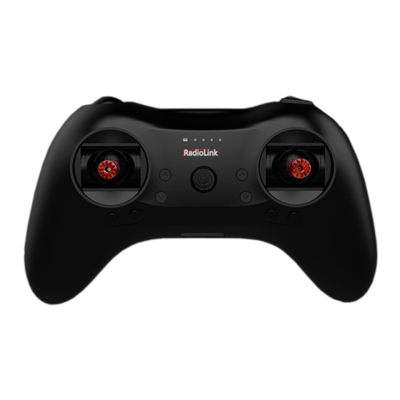
1.2.2 Packing List T8S Transmitter *1 R8EF Receiver *1 USB Cable(Update&Charge) *1 Throttle Return Accessories *1 User Manual *1 Packing Box *1 1.2.3 Transmitter Overview T8S (Mode 2) is shown as below T8S Buttons and Switches: Power button: Long press to turn on/off T8S. Throttle/Rudder/Aileron/Elevator Stick: The default Channel 1 to Channel 4 controls the roll, pitch, throttle and yaw of the aircraft. -
Page 7: Transmitter Battery
APP to control the equipment connected to this channel. (Note: If you have purchased RadioLink RTF fixed wing or racing drone that come with a T8S transmitter, the three-way switches control the switching of the flight mode by default.) - Page 8 (2) SBUS/PPM Working Mode Receiver indicator is Blue(Purple) with 8 channels output in total. Channel 1 is SBUS signal, channel 2 PPM signal and channel 3 to 8 PWM signal. Note: Fixed wing equipped with flight controller is taken as an example.
-
Page 9: Guide Of Receiver Install
(1) Please test RSSI (Received Signal Strength Indicator) before operating models. For methods on how to test it, please refer to https://www.radiolink.com/newsinfo/477894.html (2) If the antenna of the receiver is damaged, replace it with a new antenna or receiver in time. -
Page 10: Chapter 2 Parameters Setup App
② Click to enter the APP, a message will pop out to ask for permission to turn on the Bluetooth function. ③ Click CONNECT on the top left of interface, a list of devices will pop out for selection. ④ Select RadioLink device, the two LED indicators at rightmost will flash with DD sounds. -
Page 11: Mobile Phone App Parameters Setup Menu
“CONNECT”. Please check whether the “Location Information” of your phone is turned on, if not, please open the “Location Information”; If the “Location Information” is on, but you still can’t find “RadioLink Bluetooth device”. Please open the application in the phone --settings-application management--T8S&T8FB permissions--location information, change the location information from “only allowed during... - Page 12 (DIS)CONNECT: When APP is opened and T8S is powered on, click CONNECT and a list of Bluetooth devices will pop out and select the RadioLink device to make connection. The two LED at the rightmost will flash with DD sounds, press any of the trimmer buttons to stop the DD sounds and the servo range will display on the APP.
-
Page 13: Software App On Computer
2.2 Software APP on Computer 2.2.1 Software APP Installation on Computer Go to the official website https://www.radiolink.com/t8s_apps to download the computer software APP, and run the program below. If it’s your first time to use computer parameter APP, you need to install the driver before using it. - Page 14 (3) T8S will make DD sounds, press any of the trimmer buttons to stop the D sounds. READ: Click READ, two short D sounds will be heard and the APP starts reading the data in T8S. Every time the APP is reopened, the data displayed is the initial default value. If the parameters are modified, you need to click to “READ”...
-
Page 15: Chapter 3 Function Setup Menu On App
Chapter 3 Function Setup Menu on APP 3.1 SERVO Menu The 8 rectangles show the CH1-CH8 servos range instantly (4 basic channels and 4 auxiliary channels) from left to right. CH1--Aileron, CH2--Elevator, CH3--Throttle, CH4--Rudder, CH5 to CH8--Auxiliary channels. There is a real-time display when you are toggle any channel switch, it is suitable for set up complex mix control functions. -
Page 16: Basic Menu
3.2 BASIC Menu 3.2.1 REVERSE This function is to change the direction of the servo in response to the remote controller input. Make sure to check all servos move to the correct direction as wish under control. Note: If programmable mix control function is used to control several servos for fixed wing/gliders, e.g. -
Page 17: Sub-Trim
3.2.2 SUB-TRIM Makes small changes or corrections to the neutral position of each servo. The default is 0 setting by factory setting. That is, no SUB-TRIM. The range is from -100 to +100 and can be modified with actual need. The interface of parameter setup APP on phone. -
Page 18: End Point Adjustment (Epa)
3.2.3 END POINT ADJUSTMENT (EPA) This function is used to set travel range of the servo connected to the channel. When setting the model or after the first flight, if you feel that the movement of the model is still relatively small when you move the joystick to the maximum position. You can increase the travel range percentage of the corresponding channel of the servo (the maximum can be adjusted to 120, The default is 96). - Page 19 According to your needs, set the servo travel range output by the channel. After setting it, the receiver will continue to output the servo travel range according to the value you set when the receiver loses the control of transmitter. The interface of parameter setup APP on phone.
-
Page 20: Delay
3.2.5 DELAY Adjusts the synchronous ratio between the servos position and the actual operation. The default value is 100 by factory setting meaning no delay. The interface of parameter setup APP on phone. The interface of parameter setup software on computer. 3.3 ADVANCED Menu 3.3.1 D/R (Dual Rate) The model can be controlled to work on different servo travel range by a switch. - Page 21 Channels 1 to 4 can be set for different servo travel range both individually and at the same time. When setting one channel for different servo travel range, click “WRITE” after setting D/R value for the corresponding channel. When setting 4 channels for different servo travel range at the same time, click “WRITE”...
-
Page 22: Attitude
The interface of parameter setup software on computer. 3.3.2 ATTITUDE Select the preferred channel from CH5 through CH8. CH5 is always the default switch to change attitude when connect to flight controller PIXHAWK/MINI PIX/crossflight/APM/TURBO PIX with multi-rotor firmware, and CH8 is the default switch with fixed-wing firmware, while CH7 is default when connect to DJI flight controller. -
Page 23: Elevon
The interface of parameter setup APP on phone. The interface of parameter setup software on computer. 3.3.3 ELEVON “Elevator mix” is also known as “delta wing mix”. It is often used for delta wing aircraft. Two servos can control two servos surfaces that on the left and right sides of the aircraft separately, and operate aileron function and elevator function. -
Page 24: V-Tail
The specific value is the amount of servo travel range when the corresponding channel performs the aileron or elevator operation. Positive and negative values represent different directions of movement. The interface of parameter setup APP on phone. The interface of parameter setup software on computer. 3.3.4 V-TAIL V-TAIL used for fixed wing with v-tail. -
Page 25: Prog.mix Menu
The interface of parameter setup APP on phone ELEV 1 and RUDD 2 correspond to the response rate of channel 2 when performing elevator operation and rudder operation. ELEV 2 and RUDD 1 correspond to the response rate of channel 4 when performing elevator operation and rudder operation. - Page 26 Programmable mixing controls are to: ① Diversify attitude changes of aircraft (e.g. Rolling to realize when rudder is commanded); ② Control a certain axis with two or more servos (e.g. 2 rudder servos); ③ Correct special movement automatically (e.g. Lower FLAP and ELEVATOR servos at the same time);...
-
Page 27: Th/Cure
The interface of parameter setup software on computer. There are also 4 groups of programmable mix control that can be set in the computer parameter software. 3.4.2 TH/CURE Throttle curve (TH/CURE) is the set output travel by throttle. It is to coordinate the motor response and the throttle operation. -
Page 28: Dr/Cure
3.4.3 DR/CURE Please refer to Chapter 3.3 ADVANCE Menu. 3.4.4 SYSTEM Menu 3.4.4.1 AUX.CH The CH1/2/3/4 of the T8S transmitter are 4 basic channels, and CH5/6/7/8 are auxiliary channels. The switch of the basic channel cannot be modified. But different switches can do some auxiliary functions by setting CH5/6/7/8, such as control the opening and closing of the bait hopper, control whether the machine releases smoke or not etc. -
Page 29: Alarm
(Note: R8EF receiver does not support receiver voltage telemetry) EXT-ALARM To return the model voltage, RadioLink receivers of telemetry functions such as R8XM, R8FG, R7FG or R8F should be used. small adjustments are also supported. When the model voltage goes lower than the set value, T8S will make “DDD”... -
Page 30: Version Mode
The best RSSI-ALM is depends on the control range test at your flying area. For example, you have tested the control distance of your T8S is 2000 meters at your flying area, and the RSSI shows -86dBm at this time, then you can set the RSSI alarm data is -86dBm. The interface of parameter setup APP on phone The interface of parameter setup software on computer 3.4.4.3 Version MODE... - Page 31 Mode 3: left joystick-Aileron and Elevator, right joystick-Rudder and Throttle Mode 4: left joystick- Aileron and Throttle, right joystick-Rudder and Elevator VERSION The numbers mean current firmware versions. The detailed steps of firmware upgrade please refer to Chapter 2. APP-VERSION The numbers mean current Parameter Setup APP versions.
-
Page 32: Reset
3.4.4.4 RESET This function is to restore the factory setting when necessary. When press this “RESET” button, T8S will make three slow D sounds, meaning default setting is set. The interface of parameter setup APP on phone The interface of parameter setup software on computer... -
Page 33: Chapter 4 Firmware Upgrade
The interface of parameter setup APP on phone The interface of parameter setup software on computer 4.2 Firmware Upgrade Steps Please refer to the link https://www.radiolink.com/t8s_firmwares to download the latest firmware of T8S and view the detailed steps on how to update it. -
Page 34: Chapter 5 T8S Joystick Calibration
Chapter 5 T8S Joystick Calibration When the joystick of the T8S is not in the center position, or there is large difference of the travel amount, T8S needs to be calibrated. T8S joystick calibration method is as follows: 1. When the transmitter is power-off, toggle both sticks at the central point. Press rudder trimmer button (The first button on the left) and turn on transmitter at the same time. -
Page 35: Technical Support
Facebook Messenger If the above communication cannot solve your problem, you can also send emails to our technical support: after_service@radiolink.com.cn This content is subject to change. Download the latest version from https://www.radiolink.com/t8s_manual Thank you again for choosing RadioLink product.
Need help?
Do you have a question about the T8S(BT) and is the answer not in the manual?
Questions and answers