
Related Manuals for AE Techron 2105


Summary of Contents for AE Techron 2105
- Page 1 2105 Operator’s Manual Gradient Amplifier 574.295.9495 | www.aetechron.com 2507 Warren Street, Elkhart, IN 46516...
- Page 2 ORIGINAL COMMERCIAL PURCHASER we will give you an authorization to return the product ONLY of each NEW AE TECHRON INC. product, for a for service. All components must be shipped in a factory period of one (1) year from the date of purchase, by the...
-
Page 3: Declaration Of Conformity
DECLARATION OF CONFORMITY Technical Construction File Route Issued By: AE Techron, Inc. For Compliance Questions Only: Larry Shank 2507 Warren Street 574-295-9495 Elkhart, IN 46516 lshank@aetechron.com Equipment Type: Industrial Power Amplifiers Model Name: 2105 EMC Standards: EN 61326-1: 2013 – Electrical Equipment for Measurement, Control and Laboratory use —... -
Page 4: Table Of Contents
Contents 1 Introduction ............................6 Features ..........................6 2 Amplifier Unpacking and Installation ....................7 Safety First .........................7 2.2 Unpacking ..........................7 Installation ..........................7 3 Connections and Startup .......................8 3.1 Other Operation Modes and Configurations ..............8 3.2 Connecting the Load ......................8 3.3 Connecting the Input Signal ....................9 3.4 Connecting the AC Supply ....................9 Start-up Procedure......................10 4 ... - Page 5 List of Figures Figure 1.1 – 2105 Front Panel .......................6 Figure 3.1 – Close-up of the Output Terminal Resistor ..............9 Figure 3.2 – Controlled Voltage Hookup ..................9 Figure 3.3 – Close-up of SIM card ....................9 Figure 3.4 – Input Select switch functions on the Input Terminals ..........10 Figure 3.5 – Close-up of AC Mains Outlet ...................10 Figure 3.6 – Sample of Configurations Setting Label ..............10 Figure 4.1 – Power Switch ......................11 Figure 4.2 – Gain Control......................11 Figure 4.3 – Push Buttons ......................11 Figure 4.5 – Main Status Indicators for Stand-Alone Amplifiers...........12 Figure 4.4 – Main and Fault Status Indicators ................12 Figure 4.6 – Fault Status Indicators for Stand-Alone Amplifiers ..........13 Figure 4.7 – Main Status Indicators for Multi-Amplifier Systems ..........14 Figure 4.8 – Fault Status Indicators for Multi-Amplifier Systems ..........15 Figure 4.9 – Back Panel Controls and Connectors ..............16 Figure 5.1 – Access Panel Screw Locations ................17 Figure 5.2 – Main Board Location Inside Access Panel...............17 Figure 5.3 – Master/Slave Setting....................18 Figure 5.4 – Gain Trim Control.....................18 Figure 5.5 – Controlled-Voltage/Controlled-Current Mode Setting ..........19 Figure 5.6 – Compensation Setting .....................19...
-
Page 6: Introduction
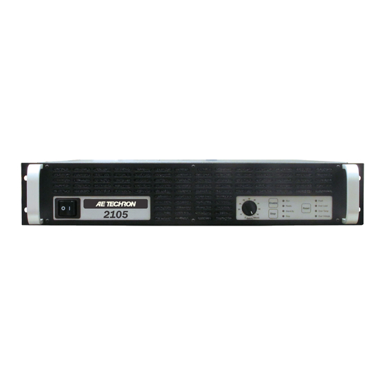
Figure 1.1 – 2105 Front Panel 1 Introduction The AE Techron 2105 is a high-power, DC-enabled • Current mode response: DC-5 kHz (compen- linear amplifier and integrated power supply that sation dependent); Voltage mode response: offers a wide bandwidth and exceptional control of DC-20 kHz at rated power. drift and distortion. The 2105 functions as a volt- • Efficient design and light-weight chassis materi- age or current source and operates using single- als allow amplifier to occupy only 2U height, phase power, making it ideal for use in the lab or and weigh only 41 lbs. classroom. Its linear design provides a very-low • Robust, linear power supply results in extreme- noise floor and fast current rise times. Because ... -
Page 7: Amplifier Unpacking And Installation
• Toolkit (contains one #2 Phillips screwdriver voltages are present in both the AC input supply and four rubber feet) and the output of this amplifier. For this reason, • Power Cord safety should be your primary concern when you • 2105 Operator’s Manual and Quick Start sheet setup and operate this amplifier. Installation Safety First The 2105 amplifiers are packaged in a rugged Throughout this manual special emphasis is powder-coated aluminum chassis. This chassis is placed on good safety practices. The following 2U (rack units) tall, and has rack “ears” on each graphics are used to highlight certain topics that ... -
Page 8: Connections And Startup
Multi-Amp Configuration Other Operation Modes and Guide (available for download from aetechron.com) Configurations for information on Parallel system configuration. The 2105 amplifier can be field-configured for For Parallel operation in Controlled-Current operation in a number of different ways. These mode, please contact AE Techron Technical would include Controlled-Voltage or Controlled- Support for assistance. Current mode, and it also can be configured for Connecting the Load operation as a part of a multi-amplifier system. These alternate configurations may require special 3.2.1 Preparation and Cautions output wiring and/or additional components. -
Page 9: Connecting The Input Signal
2105 OPERATOR’S MANUAL – SECTION 3 terminated with #8 to ¼ in. ring terminals, tinned wires up to 10GA in size, or bus bars with 0.20 in. (5 mm) OD holes (minimum) up to 0.50 in. (12.7 mm) OD holes (maximum) are recommended when connecting to the output terminals. Connect the load across the terminals marked “OUTPUT” (positive) and “COM” (negative/ ground). The third terminal, “CHASSIS GROUND” Figure 3.1 – Close-up of the Output Terminal Resistor is connected to the amplifier chassis/power cord ground and can be connected to an external ground point such as the rack chassis. See Figure 3.2. Connecting the Input Signal The signal is connected to the amplifier through a “SIM” (Specialized Input Module) located on the amplifier back panel (see Figure 3.3). The SIM card offers the choice of BNC or terminal block input connectors. -
Page 10: Start-Up Procedure
2105 OPERATOR’S MANUAL – SECTION 3 Figure 3.6 – Sample of Configurations Setting Label Review the factory-set supply voltage and ampli- fier configuration detailed on the label placed on the side of the amplifier (see Figure 3.6). This configuration can be changed by the user. See the “Advanced Configuration” section for more information. Start-up Procedure 3.5.1 Voltage-Mode Operation Perform the following steps to startup and operate your amplifier in Controlled-Voltage. Figure 3.4 – Input Select switch functions on the 1. Turn down the level of your signal source. Input Terminals 2. Turn down the gain control of the amplifier. 3. Depress the POWER switch to turn the amplifier ON. 4. Wait for the yellow READY and green RUN LEDs to illuminate. 5. Adjust the level of your input signal source to achieve the desired output level. -
Page 11: Amplifier Operation
2105 OPERATOR’S MANUAL – SECTION 4 4 Amplifier Operation Front-Panel Controls This section provides an overview of Front-Panel controls and indicators found on the 2105. 4.1.1 Power Switch The Power Switch controls the AC mains power to Figure 4.1 – Power Switch the amplifier. Switch to the ON position (|) to turn the amplifier on. Switch to the OFF position (O) to turn the amplifier off. See Figure 4.1. The Power Switch also serves as a Breaker. When the Breaker is tripped, the Power Switch moves to a neutral position between ON and OFF. -
Page 12: Figure 4.5 - Main Status Indicators For Stand-Alone Amplifiers
2105 OPERATOR’S MANUAL – SECTION 4 Enable button is pressed on each amplifier, that amplifier will be placed in Ready mode (Ready and Standby LEDs lit) and remain in Ready mode until all amplifiers in the system have been Enabled. The system will automatically proceed to Run mode when all amplifiers in the system achieve Ready mode. Figure 4.4 – Main and Fault Status Indicators Stop – For stand-alone amplifiers, Stop will place the amplifier in Standby mode (both Standby and all of the amplifiers to Run mode if the condition Stop LEDs will be lit). When the amplifier is part of causing the fault condition has been cleared; how- a multi-amp system, pressing the Stop button on ever, pressing the Reset button on other amplifiers any amplifier in the system will place all amplifiers in the system will NOT clear the fault condition. in Standby mode. When an amplifier is in Standby Refer to the “Fault Status Indicators” section for mode, the low-voltage transformer is energized but ... -
Page 13: Figure 4.6 - Fault Status Indicators For Stand-Alone Amplifiers
2105 OPERATOR’S MANUAL – SECTION 4 4.1.5 Fault Status Indicator ration of the unit, the amplifier may be placed in Four Fault Status indicators are located on the amplifier front panel (see Figure 4.4). These LEDs Standby mode when a fault condition occurs. Re- fer to the chart in Figure 4.6 to determine the fault monitor the internal conditions of the amplifier condition being indicated and the action required and will illuminate when a fault condition occurs. -
Page 14: Figure 4.7 - Main Status Indicators For Multi-Amplifier Systems
2105 OPERATOR’S MANUAL – SECTION 4 4.1.6 Main Status Indicators for 4.1.7 Fault Status Indicators for Multi-amplifier Systems Multi-Amp Systems The Main Status indicators on each amplifier in The four Fault Status indicators located on each a multi-amp system are used to determine the amplifier’s front panel are used to monitor the operational status of the amplifier. When evaluated internal conditions of the amplifier and will illumi- along with the statuses of other amplifiers in the nate when a fault condition occurs. All amplifiers in system, the Main Status indicators can be used... -
Page 15: Figure 4.8 - Fault Status Indicators For Multi-Amplifier Systems
2105 OPERATOR’S MANUAL – SECTION 4 fier displaying the Fault status. Refer to the chart indicated and the action required to clear the fault in Figure 4.8 to determine the fault condition being condition and return the system to Run mode. Figure 4.8 – Fault Status Indicators for Multi-Amplifier Systems Indicator is lit Indicator is not lit Indicator may be lit One or More Amps in System Main Status... -
Page 16: Back-Panel Controls And Connectors
Back-Panel Controls and Connectors ground through a 4.7-ohm resistor, allowing the This section provides an overview of Back-Panel controls and connectors found on the 2105 ampli- connectors to be used for Unbalanced input wir- ing. When the Input Select switch is in the RIGHT fier. Please refer to Figure 4.9 for visual locations. position, the inverting (–) pin on the terminal block AC Supply - Standard 20 amp 3-pin IEC-type connector is floating, allowing the connector to be ... -
Page 17: Advanced Configuration
2105 OPERATOR’S MANUAL – SECTION 5 5 Advanced Configuration WARNING The 2105 amplifier was designed to offer excep- tional versatility in operation. You can choose from Do not attempt to access the Main Board a range of field-configurable options, including: while the amplifier is running. Turn the amplifier off and disconnect the AC • Operate as a stand-alone amplifier or as part of Mains before removing the amplifier front panel. -
Page 18: Configuration Settings Located On The Main Board
P1 and P2 in the Slave position (jumpers across bottom two pins of each set). See Figure 5.3. For complete information on multi-amp system configuration and wiring, please consult the AE Techron Multi-Amp Configuration Guide avail- Figure 5.3 – Master/Slave Setting able for download from the AE Techron website at www.aetechron.com. 5.2.2 Fixed Gain/Variable Gain Setting The 2105 amplifier ships with an enabled Gain Control knob (located on the amplifier front panel). To disable the Variable Gain control and set for a Fixed Gain of 20, locate and unplug the red con-... -
Page 19: Figure 5.5 - Controlled-Voltage/Controlled-Current Mode Setting
2105 OPERATOR’S MANUAL – SECTION 5 CAUTION In Controlled-Current Mode, the load is part of the amplifier circuit, and the relationship of the load to the amplifier is critical. For proper and safe operation in Controlled-Current mode, you must obverve the following guidelines: 1. Properly attach a load before operating the amplifier. Use only the Output and Sampled Common terminals. DO NOT use the Common terminal. 2. DO NOT use a blocking capacitor. The load must have a DC path. 3. Never leave the load open. If you feel the load must be fused, which could lead to a poten- tial open circuit, please contact AE Techron Application Engineering department. ... -
Page 20: Configuration Settings Located On The Power Supply Board
2105 OPERATOR’S MANUAL – SECTION 5 5.2.5 Ready/Run Mode or Standby Mode Power-up The 2105 amplifier will bypass Standby Mode and cycle directly to Ready/Run Mode on power-up when Jumper J11 is in the Left position (factory default). To set the amplifier to power-up to Stand- by Mode, place Jumper J11 in the Right position. See Figure 5.7. Figure 5.7 – Run Mode/Stop Mode on Power-Up Setting 5.2.6 Standby Mode on Overload When enabled, the 2110/2120 amplifier will move into Standby Mode when it senses an activation of the IOC (Input/Output Comparator) Distortion Alert ... -
Page 21: Figure 5.9 - Accessing The Power Supply Board
2105 OPERATOR’S MANUAL – SECTION 5 Use the following general guidelines to select the best combination of settings to fit your requirements: LOAD OUTPUT Continuous Pulse Settings High 16, 8, 4 180 V Voltage 16, 8 ohm Auto 90 V Mid-Level 4, 2 ohm 2, 1 ohm Auto High 0.75 - 0.25 90 V Current 1, 0.5 ohm Figure 5.10 – Location of Amplifier High-Voltage ... -
Page 22: Figure 5.13 - Bi-Level Power Switch Location
2105 OPERATOR’S MANUAL – SECTION 5 5.3.4 Changing Bi-Level Power Supply Function The 2105offers three Bi-Level switch settings: Automatic, High, or Low. The user can select between settings via a switch on the Power Supply Board. To access and change the Bi-Level Power Switch, follow these steps: Figure 5.13 – Bi-Level Power Switch Location 1. Locate the SIM Input Card on the right side of the rear panel of the amplifier. 2. Using a #2 Phillips screwdriver (provided), 5.3.5 Selecting the Best Voltage Po- remove the 2 screws located at the edges of tential and Bi-Level Power Switch the SIM card. Settings for Your Application 3. -
Page 23: Applications
2105 OPERATOR’S MANUAL – SECTION 6 6 Applications Conversely, when configured as a Controlled- Controlled Current Operation Current source (transconductance amplifier), the The procedures outlined in this section assume amplifier will provide an output current that is con- competence on the part of the reader in terms of stant and proportional to the control (input) volt- amplifier systems, electronic components, and age. If the load’s impedance changes, the amplifier good electronic safety and working practices. -
Page 24: Figure 6.3 - Factory-Installed Default Rc Network
2105 OPERATOR’S MANUAL – SECTION 6 When operating in Controlled Current (CC) mode, 6.3), or CC2 which allows installation of a custom a compensation circuit is required to ensure ac- RC network. curate output current. Since the load is a critical circuit component in CC mode, the inductive and resistive values of the load will determine the required compensation values. While the factory- default compensation setting will be sufficient for some applications, the compensation setting may also be adjusted in the field. The following section describes methods for determining and setting proper compensation when operating in Controlled-Current mode. - Page 25 2105 OPERATOR’S MANUAL – SECTION 6 STEP 6: Installing an RC Network for If your load inductance falls outside of the mid- Custom Compensation range, or if your load resistance is greater than 5 ohms, then you must calculate your required If the default RC network does not provide suit- compensation. If, after calculating your required able compensation for your intended load, you compensation, you determine that the default com- will need to install a custom RC network that is pensation will be insufficient for your load, then ...
-
Page 26: Figure 6.5 - Compensation Effects On Waveform
2105 OPERATOR’S MANUAL – SECTION 6 Figure 6.4 – Custom Compensation Location To begin testing, input a square wave with a fre- quency of 100 Hz to 1 kHz, or a squared pulse at a low level (typically 0.25 to 2.0 volts). A limited-rise- time, repetitive pulse of low duty cycle is preferred. Observe the output current through a current monitor or current probe. Look for clean transition edges. The presence of ringing or rounding on the Figure 6.6 – Square Wave Showing a transition edges indicates compensation problems. Decrease in R is Required (See Figure 6.5.) Figure 6.7 – Square Wave Showing an Increase in R is Required Figure 6.5 – Compensation Effects on Waveform If a change in compensation is necessary, an ad- justment to the resistor component of the Compen- sation circuit is probably required. If the output current waveform is ringing, the circuit Figure 6.8 – Square Wave Showing an is underdamped: You have too much gain and Increase in C is Required should lower the resistance (see Figure 6.6). -
Page 27: Remote Status And Control Using The Sim Interlock I/O Connector
2105 OPERATOR’S MANUAL – SECTION 6 When making adjustments: NOTE: Resistor: Increase or decrease resistance values • If possible, use 1% metal film resistors. AE in increments of +/- 10%. Techron discourages installation of potentiome- ters in the resistor location of the compensation Capacitor: Incrementally increase capacitor val- circuit because this can decrease stability and ues by a factor of 2 or 3. -
Page 28: Figure 6.10 - Remote Status And Reset Schematic
2105 OPERATOR’S MANUAL – SECTION 6 6.2.1 Remote Amplifier Status and Level when Deasserted: 0V Reset Note: When amp is normal, this pin is pulled to –24V through a 47.5K-ohm resistor; when amp The SIM Interlock I/O Connector can be used to is in Overtemp state, transistor Q37 turns on and create a circuit to monitor remotely one or more sources chassis ground as an output. Do not ex-... -
Page 29: Figure 6.11 - Remote Run/Standby Monitor
2105 OPERATOR’S MANUAL – SECTION 6 Level when Deasserted: 0V Level when Deasserted: 0V Note: When amp is normal, this pin is pulled to Note: When amp is normal, this pin is pulled to –24V through a 47.5K-ohm resistor; when amp –24V through a 47.5K-ohm resistor; when amp is in Overload state, transistor Q36 turns on and is in Overvoltage state, transistor Q29 turns on ... -
Page 30: Figure 6.12 - Remote Enable/Standby
Remote Monitoring of Current Using the SIM-BNC Interlock connector located on the back panel of the amplifier, you can remotely monitor both voltage and current output. Use a male, 25-pin D-Sub connector and high- quality wire to build the desired circuits. Remote Monitoring of Current Output Purpose: Use a voltage meter to monitor output current. Method: Connect a voltage meter to monitor the output current being produced by the ampli- fier. Connect across PIN 6 (I MON+) and PIN 10 (Sampled Common). See Figure 6.13. Signal Type: DC Level when Asserted: 2105: 5A/V; 2110/2120: 20A/V Level when Deasserted: 0V Figure 6.13 – Remote Current Monitoring Information subject to change 97-2105006_4-2-15... -
Page 31: Multi-Amplifier Systems
6.15. Signal Type: DC Level when Asserted: 3-5 Vdc Level when Deasserted: 0-1 Vdc Figure 6.15 – Blanking Activation Multi-amplifier Systems contact AE Techron Application Support for infor- The 2105 amplifier may be used with other same- mation on these more complex multi-amp systems. model amplifiers to increase voltage or current. Because the internal circuitry of a 2105 amplifier For routine, controlled-voltage applications , is not connected to chassis ground, the amplifier Series or Parallel amplifier systems can be config- is well suited for use in series or parallel with other ured using the following accessories available from ... -
Page 32: Accessory Recommendations By System Type
Removable Barrier Block (WECO) connectors and the SIM-BNC-OPTOC module (see above) the input terminators required during system setup. BAL RES KIT – Three types available: 2105 BAL Parallel wiring kits are recommended for all Paral- RES KIT, 2110 BAL RES KIT and 2120 BAL RES lel configurations. KIT. Ballast resistors are required for all Parallel To download the AE Techron Multi-Amp Configu- configurations. The ballast resistor kits include one ration Guide or for additional information, visit the ballast resistor (two in the 2120 kit) with connec- AE Techron website at www.aetechron.com. tion terminals and mounting hardware. The 2105 6.3.1 Accessory Recommendations by System Type Series Systems... - Page 33 2105 OPERATOR’S MANUAL – SECTION 6 Two 2105s in Series – High-Voltage Mode PEAK OUTPUT RMS OUTPUT 40 mSec Pulse, 5 Minutes, 1 Hour, 5 Minutes, 1 Hour, 20% Duty Cycle 100% Duty Cycle 100% Duty Cycle 100% Duty Cycle 100% Duty Cycle Ohms Volts Amps Volts Amps Volts Amps Volts Amps Volts Amps Watts 1539 16.3...
- Page 34 2105 OPERATOR’S MANUAL – SECTION 6 Three 2120s in Series – High-Current Mode PEAK OUTPUT RMS OUTPUT 40 mSec Pulse, 5 Minutes, 1 Hour, 5 Minutes, 1 Hour, 20% Duty Cycle 100% Duty Cycle 100% Duty Cycle 100% Duty Cycle 100% Duty Cycle Ohms Volts Amps Volts Amps Volts Amps Volts Amps Volts Amps Watts 61.5 20.5...
- Page 35 2105 OPERATOR’S MANUAL – SECTION 6 Three Paralleled 2105s – Mid-Level Mode PEAK OUTPUT RMS OUTPUT 40 mSec Pulse, 5 Minutes, 1 Hour, 5 Minutes, 1 Hour, 20% Duty Cycle 100% Duty Cycle 100% Duty Cycle 100% Duty Cycle 100% Duty Cycle Ohms Volts Amps Volts Amps Volts Amps Volts Amps Volts Amps Watts 1.34 49.2 49.2...
-
Page 36: Amplifier Signal Flow
2105 OPERATOR’S MANUAL – SECTION 7 7 Amplifier Signal Flow AC Mains Power Power to the amplifier is connected through a 20- Input Signals amp IEC-type inlet connector with an integral EMI The input signal is routed from the SIM (Specialized filter network on the back panel. AC mains power is Input Module) on the back panel to the Main board. first routed through the front panel switch/breaker, From there, the signal is amplified through low-noise then to the Power Supply board. From there, the AC operational amplifier gain stages, compensation mains are distributed to the main power transform- networks, and current limiting/ODEP and then final ers, and then from the transformers back through the gain stage to the Output board. At the Output board, ... -
Page 37: Maintenance
2105 OPERATOR’S MANUAL – SECTION 8 8 Maintenance Clean Amplifier Filter and Grills 8.1.1 Tools Required Simple maintenance can be performed by the user The recommended equipment and supplies to help keep the equipment operational. The fol- needed to perform the functions required for this lowing routine maintenance is designed to prevent task are described below. problems before they occur. See Section 8, Trou- bleshooting, for recommendations for restoring the • Vacuum cleaner equipment to operation after an error condition has ... -
Page 38: Troubleshooting
7. Inspect the entire lengths of wires and ribbon DANGER cables for breaks or other physical damage. 8. If there is any physical damage to the amplifier, Uninsulated terminals with AC Mains please return it to AE Techron for repair. potential are exposed when the panel is removed. Do not proceed until AC Mains have been disconnected. Figure 9.1 – +Vcc and –Vcc Point Locations Information subject to change... -
Page 39: No Signal
2105 OPERATOR’S MANUAL – SECTION 9 No Signal Missing Output signal may be caused by one of the following: 1. Master/Slave Jumpers are set to the Slave (down) position. The amplifier should only be configured for Slave mode if it is in a multi-ampli- fier system; otherwise it should be set for Master mode. See the “Advanced Configuration” sec- tion in this manual for more information. 2. Signal is not connected to any inputs on the SIM card. See the “Amplifier Setup” section in this manual for more information. No LEDs Illuminated or No Fans If none of the LEDs on the Display Panel are il-... -
Page 40: Amplifier Overheats (Over Temp Fault Condition)
2105 OPERATOR’S MANUAL – SECTION 9 Amplifier Overheats (Over Temp the input signal from the amplifier. Allow the fans to Fault Condition) run for five minutes, and then push the Reset but- ton to reset the amplifier. There are two possible reasons why the 2105 am- plifier is overheating: Fault LED is Illuminated 1. Excessive Power Requirements The 2105 contains protection circuitry that disables 2. Inadequate Airflow the amplifier if an output stage is behaving abnor- 9.7.1 Excessive Power Requirements mally. - Page 41 2105 OPERATOR’S MANUAL – SECTION 9 Please take extra care when packaging your am- Please send all service units to the following ad- plifier for repair. It should be returned in its original dress and be sure to include your Return Authori- packaging or a suitable alternative. Replacement zation Number on the box. packaging materials can be purchased for a nomi- AE Techron, Inc. nal fee. Attn: Service Department / RMA# 2507 Warren Street Elkhart, IN 46516 Information subject to change 97-2105006_4-2-15...
-
Page 42: 10 Specifications
2105 OPERATOR’S MANUAL – SECTION 10 10 Specifications 2105 Pulsed Output - Current Mode PULSE DURATION / OFF TIME (mS 500 / 500 100 / 100 10 / 20 170 / 1000 25 / 1000 4 / 100 Output (±A Peak) 8.75 11.7 *DC 1Ω 10.1 Performance Specification typical at 25°C ambient. Unless otherwise noted; testing was done in Current mode with a load = 500 µH +100 mΩ. Peak Current Limit 55 A Gain (adjustable) Voltage Mode: 20 to 0.2 V/V Current Mode: 5 to 0.2 A/V... - Page 43 2105 OPERATOR’S MANUAL – SECTION 10 Amplifier Protection Over Load/Distortion (IOC): Shutdown or clipped output Current vs Time (ODEP): Clipped output Each heat sink temperature: Shutdown 105°C Overvoltage Shutdown: 132 VAC / 253 VAC Undervoltage Shutdown: 108 VAC / 207 VAC Status Indicators (front panel) LEDs indicate a status of Run, Ready or Standby, and Fault, Over Temp, Over Voltage, and Over Load conditions Controls (front panel) Soft Touch Switches: Run (Enable), Stop and Re- set functions Gain Control, when-enabled: Voltage gain adjust-...
- Page 44 Not recommended for normal customer use. amplifier use; not recommended for normal customer use. Line has series resistor and unloaded will go from 0V (not ready) to -15V (ready), with an OPTOC BNC card the signal will go from 0V (not ready) to -1.2Vdc (ready) I MON + Differential Current AC or 2105: 5A/V Output current produced per voltage Current Monitoring: Connect a voltage meter to mon- Monitor + 2110/2120: detect. itor the output current being produced by the amplifier. 20A/V For unbalanced, for each 1V detected, current output is 5A (2105) or 20A (2110/2120). Not currently used. None...
- Page 45 Standby of all amps in a multi-amplifier system. OEM modification only; normally no connection. OEM App Input Monitor Used to monitor the input signal (OEM only) from an OEM DAC card; this is the actual input signal. I MON – Differential Current AC or 2105: 5A/V Inverted I MON+ (PIN 6). Output Current Monitoring: Connect a voltage meter to mon- (alt.: OEM Monitor – ; 2110/2120: current produced per voltage detect. itor the output current being produced by the amplifier. App) (- Input Monitor, 20A/V For each 1V detected, current output is 5A (2105) or 20A ...
- Page 46 Pin # Function Description Signal Level when Level when Notes Applications Type Asserted Deasserted I SUM3– Multiple Amplifier Planned for use in multiple amplifier Currently not used. Summing, Amplifier configurations - paralleled and run- ning Controlled Current Mode OverLoad Overload output –24V When amp is normal, this pin is Remote Signal of Overload Condition: LED, when lit, (amplifier output is ...
Need help?
Do you have a question about the 2105 and is the answer not in the manual?
Questions and answers