
Related Manuals for AE Techron LVC608


Summary of Contents for AE Techron LVC608
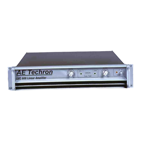
- Page 1 AE T ECHRON ® Technical Manual LVC608/LVC623 and LVC2016 Power Supply Amplifiers...
- Page 3 AE T ECHRON ® LVC608/ LVC623/LVC2016 Power Supply Amplifiers Technical Manual © AE T . 2002 ECHRON 2507 Warren St. Elkhart IN 46516 U.S.A. Phone: (574) 295-9495 Fax: (574) 295-9496 E-Mail: Sales@aetechron.com www.aetechron.com...
- Page 4 LVC 608 200HF Supplemental Manual The LVC608 200-HF has been modified to allow much higher frequencies than would normally be available, because of this several changes have been made to the input section. The LVC 608-200HF differs from the standard LVC-608 in these ways: 1) The LVC 608-200HF has a specially optimized high frequency capable input card.
- Page 5 AE T ECHRON ® Limited One-Year Warranty SUMMARY OF WARRANTY AE T . , of Elkhart, Indiana (Warrantor) warrants to you, the ORIGINAL COMMERCIAL PURCHASER ECHRON ONLY of each NEW AE T . product, for a period of one (1) year from the date of purchase, by the ECHRON original purchaser (warranty period) that the product is free of defects in materials or workmanship and will meet or exceed all advertised specifications for such a product.
- Page 7 Revision Control Revision Date 0 (Initial Release) November 2002 May 2004 Page Number Revision Number Corrections on 1-5, 1-6, 1-7...
-
Page 9: Table Of Contents
Contents Section 1- Pre Installation 1.1 Safety Conventions ............... 1-2 1.2 Product Design................1-3 1.2.1 General Description ............ 1-3 1.2.2 Specifications ............. 1-4 1.2.3 Front Panel Functions ..........1-9 1.2.4 Back Panel Functions ..........1-10 1.2.5 Plug-in Module............1-11 1.2.6 Input Card ..............1-12 1.3 Ground Loop Removal ............... -
Page 11: Section 1- Pre Installation
Pre- Installation This section describes safety conventions used within this document and provides essential information about Models LVC 608, LVC 623 and LVC 2016 amplifiers. Hereafter referred to as the LVC 608/623/2016 Series except in specific circumstances. Review this material before installing or operating the amplifier. -
Page 12: Safety Conventions
1.1 Safety Conventions The LVC 608/623/2016 Series amplifiers are highly sophisticated instruments. Accordingly, this document provides full information on the amplifiers including service procedures. Safety should be your primary concern as you use these products and follow these procedures. Special hazard alert instructions appear throughout this manual. Note the following examples: NOTE: A Note represents information, which needs special emphasis but does not represent a hazard. -
Page 13: Product Design
1.2. Product Design 1. 2. 1 General Description The AE T LVC 608/623/2016 Series are dual channel power supply ECHRON amplifiers designed for use in low and medium power systems. They accomplish this with extremely low harmonic and intermodulation distortion and low noise. All this power is concentrated into a 3.5-inch rack mount package. -
Page 14: Specifications
1.2.2 Specifications Specifications are for units in Dual Mode driving both channels into 8-ohm loads, (26 dB = 20 times voltage gain) and operating from 120 VAC, unless otherwise specified. • Standard 1 kHz Power" refers to maximum average power in watts at 1 kHz with 0.1% THD. - Page 15 LVC 608 Power Output Power: Measurements taken at 1 kHz at .05% THD with amplifiers operating in controlled voltage mode. One Channel Driven: 40mSec Burst 5 Minute 1 Hour Continuous Continuous Sine Sine Ohms Watts Volts Watts Volts Watts Volts 34.2 42.4 42.4...
- Page 16 LVC 623 Power Continuous Duty/Low Impedance Single Channel 40mSec 5 Minutes Continuous Ohms Watts Volts Amps Watts Volts Amps Watts Amps Volts 26.6 26.59 31.1 34.4 37.8 37.78 Bridged Mono (Maximum Voltage) 40mSec 5 Minutes Continuous Ohms Watts Volts Amps Watts Volts Amps...
- Page 17 LVC 2016 Power Pulse/High Impedance Single Channel 40mSec 5 Minutes Continuous Ohms Watts Volts Amps Watts Volts Amps Watts Amps Volts 1050 45.35 18.7 64.8 64.8 80.6 80.6 Bridged Mono (Maximum Voltage) 40mSec 5 Minutes Continuous Ohms Watts Volts Amps Watts Volts Amps...
- Page 18 Controls Front Panel: A push On/Off power switch; also, a signal level control for each channel. Back Panel: A 3-position switch selects Dual, Bridge-Mono, or Parallel- Mono Mode. Internal: A 3-position switch, located inside at the bottom of the input well, selects 20, 70, or 140-voltage gain for each channel.
-
Page 19: Front Panel Functions
1.2.3 Front Panel Functions The following illustration, with captioned call-outs, provides a visual location of the LVC 608/623/2016 Series front panel functions. A. Dust Filters The dust filters remove large particles from the air drawn in by the cooling fans. Check the filters regularly to prevent clogging. -
Page 20: Back Panel Functions
1.2.4 Back Panel The following illustration, with captioned call-outs, provides a visual location of the LVC 608/623/2016 Series back panel functions. G. Power Cord North American units set up for 120 VAC, 60 Hz power are shipped with a grounded 125 volt, 30 amp NEMA TT30P plug; units shipped outside North America are provided without a plug. - Page 21 1.2.5 Details of the LVC 608/623/2016 Series Plug-In Module Function 1,2, Available for additional features Standby, When Pins 3 and 4 are shorted output section of amplifier forced into standby. Ground pin for use with pins 6, 7, and 8 Voltage monitor, will have 1/20th of voltage at output of Channel 2.
-
Page 22: Input Card
1.2.6 The CCPIP Input Card Component Side View of the CCPIP Input Card Channel One Controls Adjusts common mode rejection for balanced input on channel 1. Adjusts DC offset of Channel 1 of input card (measured at Pin 7 of U4) VR10 Adjusts DC offset of Channel 1 of amplifier (measured at output of amplifier). - Page 23 Input Card Continued NOTE: C 18 - In parallel with compensation controls stability when in Constant Current Mode Channel 2 Controls: Adjusts common mode rejection for balanced input on channel 2 Adjusts DC offset of Channel 2 of input card (measured at Pin 7 of U3) Adjusts DC offset of Channel 2 of amplifier (measured at output of amplifier).
-
Page 24: Ground Loop Removal
1.3 Ground Loop Removal Hum and noise problems caused by ground loops are one of the most common problems that plague power amplifier systems. Theoretically, ground loops will never occur if one and only one ground path is allowed between the LVC 608/623/2016, the signal source and the load. The input and output grounds of the amplifier should not be externally joined since this external ground path will form a loop with the internal ground path. -
Page 25: Constant Current Compensation
1.4 Constant Current Compensation The following is a guideline for compensating amplifiers in the controlled current mode. Constant voltage mode does not require compensation. For this procedure, use C 104 and R109. Jumper JMP is in the CC position. a) Calculate the approximate value of the resistor using the following formula: Rc = 20,000 x 3.14 x L x BW •... - Page 26 Controlled Current Compensation Continued NOTE: In multiple amplifier systems, expect to decrease the value of R109 in series systems (by 1/2 for 2 units), and increase the value (double for 2 units) in parallel systems. Compensation Waveforms: Box 1 Box 2 Box 3 Box 4 From Left to Right:...
-
Page 27: Section 2- Installation
Installation This section describes general guidelines for installing the Model LVC 608/623/2016 Series Amplifier with special emphasis on system installations. 2.1 Unpacking Every AE T Model LVC 608/623/2016 is carefully inspected and tested ECHRON prior to leaving the factory. Carefully unpack and inspect the unit for damage in shipment. -
Page 28: Mounting
2.2 Mounting The LVC 608/623/2016 is designed for standard 19-inch (48.3 cm) rack mounting and "stack" mounting without a cabinet. For optimum cooling and rack support, multiple units should be stacked directly on top of each other. To reduce the risk of ELECTRIC SHOCK or FIRE HAZARD, DO NOT expose the LVC 608/623/2016 to rain or moisture. -
Page 29: Cooling
2.3 Cooling NEVER block the air vents in the front or sides of the amplifier. These amplifiers DO NOT need to be mounted with space between them. If you must leave open spaces in a rack for any reason, close them with blank panels or poor airflow will result. - Page 30 Cooling Continued At the bottom of the rack, mount the blower so it blows outside air into the space between the door and front of the amplifiers, pressurizing the chimney" behind the door. This blower should not blow air into or take air out of the space behind the amplifiers.
-
Page 31: Making Connections
2.4 Making Connections Before beginning the installation of your amplifier, please check the following: Remove all power from the unit. Do Not have the AC cord plugged in. Turn input level control down (fully counter clockwise). The input and output jacks are located on the back panel. Use care in making connections, selecting signal sources, and matching loads. -
Page 32: Dual Channel Hookup
2.4.1 Dual Channel Hookup In Dual Mode, installation is very intuitive: input Channel 1 feeds output Channel 1, and input Channel 2 feeds output Channel 2. To activate Dual Mode: 1. Turn off the amplifier. 2. Wait 10 seconds for the power supply to discharge. 3. - Page 33 Installation 2-7...
-
Page 34: Bridge-Mono Hookup
2.4.2 Bridge-Mono Hookup Bridge-Mono Mode is intended for driving loads with total impedance of 4 ohms or more (see Section 2.4.3 if the load is less than 4 ohms). Installing the amplifier in Bridge-Mono Mode is very different from the other modes and requires special attention. - Page 35 Installation 2-9...
-
Page 36: Parallel-Mono Hookup
2.4.3 Parallel-Mono Hookup Parallel-Mono Mode is intended for driving loads with a total impedance of less than 4 ohms (see Section 2.4.2 if the load is 4 ohms or greater). Installing the amplifier in Parallel-Mono Mode is very different from the other modes and requires special attention. - Page 37 Installation 2-11...
-
Page 38: Connecting Power
2.4.4 Connecting Power The LVC 608/623/2016 uses a 3-wire (grounded) AC line system. At times, the third wire ground may introduce a ground loop into the system. Each LVC 608/623/2016 is supplied from the factory with an appropriate AC cord. NOTE: Units destined for other parts of the world are provided without a plug. -
Page 39: Section 3- Applications
Applications This section describes the uses of the AE T Model LVC 608/623/2016 ECHRON amplifier, its capabilities, and various associated system configurations. Review this material before attempting to change the amplifier. 3.1 Introduction This section is included for customers who may need to customize the LVC 608/623/2016 for a new application. -
Page 40: Amplifier Capability
3.2 Amplifier Capability Model LVC 608/623/2016 is a well-built power supply amplifier. It is capable of delivering precision power levels in a wide range of demands and with a variety of loads. When demands exceed the limits, there are several ways to increase the amplifier s capability. -
Page 41: Plug-In Modules
3.3 Plug-In Modules This is an excellent way to customize the amplifier for different applications in a relatively short amount of time. The LVC 608/623/2016 amplifiers are equipped with an input module inside the back panel. The modules install easily as shown below. -
Page 42: Ac Power Applications
3.4 AC Power Applications This section provides detailed information about power drawn from the AC mains and heat dissipation by the amplifier. Also, this section shows how to change the amplifier to operate from a different AC voltage and/or frequency. 3.4.1 AC Power Draw and Thermal Dissipation The amount of power and current drawn, and the amount of heat produced under various conditions are presented here. -
Page 43: Section 4- Principles Of Operation
Principles of Operation This section of the manual explains the general operating principles of an AE LVC 608/623/2016 grounded bridge power amplifier. Topics covered ECHRON include Front End, Grounded Bridge, and ODEP. 4.1 Overview Your AE T variable impedance amplifier incorporates several new ECHRON technological advancements including low-stress output stages, real-time computer simulation of output transistor conditions, an advanced heat diffuser... -
Page 44: Features
Overview Continued The devices connected to the load are referred to as "high-side NPN and PNP" and the devices connected to ground are referred to as "low-side NPN and PNP . Positive current is delivered to the load by increasing conductance simultaneously in the high-side NPN and low-side PNP stage, while decreasing conductance of the high-side PNP and low-side NPN in synchrony. -
Page 45: Front End Operation
4.3 Front End Operation The front end is comprised of three stages: Balanced Gain Stage (BGS), Variable Gain Stage (VGS), and the Error Amp. Figure 4.1 shows a simplified diagram of a typical front end with voltage amplification stages. 4.3.1 Balanced Gain Stage (BGS) Input to the amplifier is balanced. -
Page 46: Voltage Amplification
4.4 Voltage Amplification The Voltage Translator stage separates the output of the Error Amp into balanced positive and negative drive voltages for the Last Voltage Amplifiers (LVAs), translating the signal from ground referenced ±15V to ±Vcc reference. LVAs provide the main voltage amplification and drive the High Side output stages. Gain from Voltage Translator input to amplifier output is a factor of 25.2. -
Page 47: Section 5- Service Information
Service Information This amplifier has sophisticated circuitry, which should only be serviced by a fully trained technician. 5.1 Qualified Service AE T . will provide service to the original purchaser of each new AE ECHRON LVC 608/623/2016 for a period of one (1) year from the date of ECHRON purchase if all conditions of the warranty have been met. -
Page 48: Shipping Instructions
5.2 Shipping Instructions 1. When sending an AE T product to the factory for service, be sure to ECHRON write a letter describing the problem and reason for service and enclose it inside your unit's shipping pack. 2. To assure the safe transportation of your unit to the factory, ship it in an original factory-packing container.
Need help?
Do you have a question about the LVC608 and is the answer not in the manual?
Questions and answers