
Related Manuals for AE Techron 8500 Series


Summary of Contents for AE Techron 8500 Series
- Page 1 8504 Operator’s Manual Wide-Bandwidth, High-Power Digital Amplifier 574.295.9495 | www.aetechron.com 2507 Warren Street, Elkhart, IN 46516...
- Page 3 This includes any damage to ITEMS EXCLUDED FROM WARRANTY another product or products resulting from such a This AE Techron Warranty is in effect only for failure defect. of a new AE Techron product which occurred within the Warranty Period.
-
Page 4: Table Of Contents
Contents 1 Introduction ............................5 1.1 Features ..........................5 1.2 Configuration Options......................5 2 Amplifier Unpacking and Installation ....................6 2.1 Safety First ..........................6 2.2 Unpacking ..........................6 2.3 Installation ..........................6 3 Connections and Startup .......................6 3.1 Connecting the Load ......................7 3.2 Connecting the Input Signal ....................7 3.3 Other DIP Switch Settings .....................8 3.4 Monitor and Sense Ports .......................8 3.5 Connecting the AC Supply ....................8 3.6 ... -
Page 5: Introduction
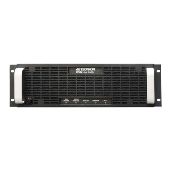
8504 OPERATOR’S MANUAL – SECTION 1 Figure 1.1 – 8504 Front Panel 1 Introduction Congratulations on your purchase of the 8504 Performance Overview digital power amplifier. 8500 Series amplifiers are the first wide-bandwidth, high-power digital amplifi- DC - 50 kHz Bandwidth ers available from any manufacturer. They are fast enough for DC automotive dropout testing and ca- 0 to 350 VDC Voltage 0 to 250 V RMS; pable of AC voltages required for ISO 61000 and Aviation testing. Plus, they have low enough noise Current 100 A and distortion specifications to be the reference power source in power quality measurements. Distortion 0.1% 1.1 Features Power 4 kW Wide Bandwidth and Flexible Apparent Power 20 kVA... -
Page 6: Amplifier Unpacking And Installation
8504 OPERATOR’S MANUAL – SECTION 2 2 Amplifier Unpacking and Installation The 8504 amplifier is a precision instrument that 2.3 Installation can be dangerous if not handled properly. Lethal The 8504 amplifiers are packaged in a rugged voltages are present in both the AC input supply powder-coated chassis. This chassis is 3U (rack and the output of the amplifier. For this reason, units) tall, and has rack “ears” on each side of the safety should be your primary concern when you front panel for mounting to a standard EIA (Elec- setup and operate this amplifier. tronic Industries Association) rack. Use standard rack mounting hardware to mount the ampli- 2.1 Safety First fier. Use nylon washers if you wish to protect the Throughout this manual special emphasis is powder-coat finish on the front of the amplifier. placed on good safety practices. The following Optionally, the amplifier can be placed on a graphics are used to highlight certain topics that bench top; please keep in mind that the protective require extra precaution. powder-coating can be scratched when placed on other equipment or on a bench top, especially DANGER when there is dirt present. To protect the finish, a DANGER represents the most severe set of rubber feet is included in the toolkit that can hazard alert. -
Page 7: Connecting The Load
8504 OPERATOR’S MANUAL – SECTION 3 Figure 3.1 – 8504 Back Panel 3.1.2 Output Connections are operating correctly. Once proper operation is confirmed, refer to the Applications section of this Connection to the output of the amplifier is to a manual for instructions on configuring and operat- pair of high-current output terminals. Wires ter- ing your amplifier in Controlled-Current mode. minated with 3/8-inch ring terminals are recom- mended when connecting to the output terminals. 3.1 Connecting the Load Connect the load across the terminals marked 3.1.1 Preparation and Cautions “OUTPUT” (positive) and “GND” (ground). The Before connecting the amplifier, make sure the GND terminal also can be connected to an ex- AC power is disconnected. -
Page 8: Other Dip Switch Settings
8504 OPERATOR’S MANUAL – SECTION 3 The back-panel DIP switch #1 can be used to en- DANGER able/disable the unbalanced input connector, and DIP switch #2 can be used to enable/disable the The risk of lethal ELECTRICAL SHOCK balanced input connector. exists when connecting AC mains! Disconnect the source before connect- ing AC power wires to the amplifier’s AC When these two DIP switches are placed in the UP inputs. position (factory default), the input connectors are enabled. When the DIP switches are placed in the 3.5 Connecting the AC Supply DOWN position, the input connectors are disabled. Always operate the amplifier from the proper AC ... -
Page 9: Amplifier Operation
8504 OPERATOR’S MANUAL – SECTION 4 4 Amplifier Operation To release the amplifier from Standby mode: 1. High/Low Line error: Clear the over- or un- 4.1 Front-Panel Controls and Indicators der-voltage condition. The amplifier will resume This section provides an overview of Front-Panel operation when the input voltage is brought controls and indicators found on the 8504. Refer fo within the operating range of the amplifier. Figure 4.1 for component locations. 2. Overtemp condition: Leave the amplifier in 4.1.1 Power Switch Standby mode with the fans operating to cool ... -
Page 10: Back-Panel Controls & Connectors
8504 OPERATOR’S MANUAL – SECTION 4 could not follow the input signal due to voltage To remove the amplifier from Standby and return or current limits. The amber Overload indicator it to normal operation after an Overtemp fault has will begin flashing when distortion is greater than occurred, make sure the amplifier fans are running and then remove the input signal from the ampli- 0.1%. fier. Allow the fans to run until the amplifier auto- 4.1.4 High/Low Line Indicator matically returns to Run mode. See the Trouble- This amber indicator will illuminate and the ampli- shooting section for information on identifying and fier will be placed in Standby if the detected AC correcting the cause of an Overtemp fault condi- mains voltage is outside of the operable range of tion. the amplifier (±10%). 4.1.6 Fault Indicator To remove the amplifier from Standby, the AC mains must be brought to within the optimal range. The red Fault indicator will light and the amplifier Once the fault condition has been cleared, the am- will be placed in Standby under two conditions: plifier will return automatically to Run mode. If the 1. High frequency oscillation is causing high High/Low Line indicator does not turn off or if the ... - Page 11 8504 OPERATOR’S MANUAL – SECTION 4 ing equipment. The voltage monitor output is 1V = Output Terminals – Connect output lines from the 40V. load to this pair of high-current output terminals using 3/8-inch ring terminals. Multi-amp Connectors – These two 9-pin D-sub connectors, labeled Interconnect A and Intercon- Unbalanced BNC Input Connector – This input nect B, can be used to connect two or more 8504 option provides a standard unbalanced input. amplifiers in a parallel configuration. They can Balanced WECO Input Connector – This input also be used to set up a Safety Interlock circuit to ...
-
Page 12: Advanced Configuration
8504 OPERATOR’S MANUAL – SECTION 5 5 Advanced Configuration The 8504 amplifier was designed to offer excep- Limit current output via programmable current • tional versatility in operation. You can choose from limits. a range of field-configurable options, including: Adjust the amplifier gain from 0.16 to 40 in • increments of 0.16. Enable the unbalanced or balanced signal input • Configure two or more 8504 amplifiers for op- • connections, or use both inputs. eration as a parallel system. Select DC-coupled or AC-coupled operation. • Enable electronic gain matching to optimize • Enable DC Servo to ensure DC offset remains • parallel operation of two or more 8504 ampli- at zero and safely drive coils and transformers. fiers. Select Controlled-Current or Controlled-Voltage • Select and enable a synthetic impedance from •... -
Page 13: Dip Switch Configurations
8504 OPERATOR’S MANUAL – SECTION 5 5.1 DIP Switch Configurations CAUTION The 8504 amplifier provides 24 DIP switches locat- ed on the amplifier back panel. Most configuration In Controlled-Current Mode, the load is part of the amplifier settings can be made using these DIP switches. circuit, and the relationship of the load to the amplifier is critical. For proper and safe operation in Controlled-Current See Figure 5.1 for default DIP switch settings and mode, you must obverve the following guidelines: descriptions. 1. Properly attach a load before operating the amplifier. SW#1: Unbalanced Input 2. Make sure a compensation network is enabled. Set switch #6 ON unless you are using a custom compenation When this switch is in the UP position (default), the ... - Page 14 8504 OPERATOR’S MANUAL – SECTION 5 For more information on Controlled-Current opera- All switches are additive and provide the following tion and installing a custom RC network, see the values toward the total Gain amount. “Applications” section of this manual. SW#9 = 20.00 SW#13 = 1.25 SW#10 = 10.00 SW#14 = 0.63 SW#6: Compensation Network 1 SW#11 = 5.00 SW#15 = 0.31 When the 8504 amplifier is used in Controlled- SW#12 = 2.50 SW#16 = 0.16 Current mode, the current control loop is tuned Refer to the chart in Appendix A to quickly deter- with an RC network. The Compensation Network mine the switch settings for your desired amplifier 1 switch enables the factory default RC network. gain.
-
Page 15: Internal Configuration
8504 OPERATOR’S MANUAL – SECTION 5 in the DOWN position, the amplifier’s output cur- ON = DIP Switch UP OFF = DIP Switch DOWN rent will be limited to 10A. Current SW#21 SW#22 SW#23 SW#24 Limit 5.2 Internal Configuration 160A 150A The 8504 amplifier contains a circuit board with 140A circuitry that can be used to install and enable a 130A custom compensation network for use in Con- 120A trolled-Current operation. A custom network may 110A be required if the default compensation network 100A (enabled by placing DIP switch #6 in the UP posi- tion) does not provide adequate compensation for ... - Page 16 8504 OPERATOR’S MANUAL – SECTION 5 Figure 5.4 – Removing the amplifier top cover To install a custom compensation network, the amplifier top cover must be removed and the front- end board must be removed from the amplifier. Complete the following steps to install a custom compensation network. Tool Required #2 Phillips screwdriver Procedure 1. Remove power from the amplifier and discon- nect any load from the amplifier outputs. Wait a minimum of three minutes to allow the ampli- fier’s capacitors to discharge. 2. Use the #2 Phillips screwdriver to remove the Figure 5.5 – Front-end board screw location 34 screws securing the top cover, as shown in Figure 5.4. 3. Lift the cover straight up to remove and set aside. 4. Locate the screw just above the voltage and current monitor BNC connectors on the ampli- fier back panel. Use the Phillips screwdriver to remove the screw. See Figure 5.5. 5. Locate the front-end board inside the amplifier chassis, as show in Figure 5.6. Gently rock the board back and forth in the board socket while pulling up on the board to release the board ...
- Page 17 8504 OPERATOR’S MANUAL – SECTION 5 Figure 5.7 – Location of Installation Area for Compensation Network 2 Figure 5.9 – Connectors location for front-end board replacement – CAPACITOR + RESISTOR Figure 5.8 – Compensation Network 2 component locations on front end board 6. Locate the installation area for the custom 8. Replace the screw securing the front-end compensation network (see Figure 5.7). Install board to the back panel. Make sure the screw the resistor and capacitor in the areas shown in hole in the back panel lines up with the screw Figure 5.8. Note: For instructions for selecting hole in the front-end board, then hold the board the best RC components for your network, see to secure it in the vertical position while you the topic “Controlled Current Operation” in the tighten the screw into place. Do not overtight- Applications section of this manual. 7.
-
Page 18: Applications
Techron ries amplifier systems can be configured using two Tech Support for assistance with configuring a standard 8504 amplifiers and the following acces- multi-amp system for Controlled Current operation. sory available from AE Techron: For routine, Controlled-Voltage applications, 8500 Series Push/Pull DB9 Cable Kit (part num- Parallel amplifier systems can be configured using ber 69-8005462) standard 8504 amplifiers and the following acces- Please contact AE Techron’s Sales Department sories available from AE Techron: for more information. 8504 Parallel DB9 Wiring Kit, 2 Amplifiers (part ... - Page 19 8504 OPERATOR’S MANUAL – SECTION 6 Figure 6.2 – Critical Wire Lengths in Parallel Systems WARNING Select wire appropriate for your application, load and expected output. Parallel systems with a high- ELECTRIC SHOCK HAZARD. impedance load running high-current, continuous- Output potentials can be lethal. Make connections only with AC Power OFF duty applications may require 1/0 AWG or more and input signals removed. Please refer to an AWG wire sizes chart or the equivalent to determine the appropriate wire for Use Proper Output Wiring your application. IMPORTANT: In a paralleled system, it is impor- tant to control the lengths of output cables. Out- Wire rating refers to the allowable voltage han- dled by the wire. In configuring Series systems for put cables should be between 2.5 and 4.0 feet in increased voltage, make sure that the wire insula- length, and the lengths of each leg of the output ...
- Page 20 8504 OPERATOR’S MANUAL – SECTION 6 Never directly connect one amplifier’s OUTPUT Operate with Safety in Mind terminal to another amplifier’s OUTPUT terminal, Potentially lethal voltages and currents are pres- unless the Electronic Gain Matching option has ent within the 8504 amplifiers. While the amplifiers’ been selected (see the Advanced Configuration chassis are earth-grounded, all internal grounds section of this manual for more information). The are floating. Particularly in systems assembled for resulting circulating currents will waste power and increased voltage (Series configuration), all inter- may damage the amplifiers. The OUTPUT terminal nal grounds of the Follower amplifier could carry of one amplifier should only be directly connected lethal voltage levels. to the load. Figure 6.3 – Multi-amp System Configuration (Parallel System) Information subject to change 96-8005353_8-12-2020...
- Page 21 8504 OPERATOR’S MANUAL – SECTION 6 6.1.4 Parallel Multi-amp Configuration B. The wires should be terminated at one To configure and connect two or more amplifiers end into a spade lug, ring terminal or other terminal suitable for the system output and for operation in a parallel configuration, begin by adaptable to the connectors on the load. designating one amplifier as the Master amplifier, and all of the other amplifiers as Follower amplifi- C. Terminate each of the legs of the cable with 3/8-inch ring terminal ends to facilitate ers. Consider placing a “Master” or “Follower” label connection to each amplifier’s output con- on each amplifier’s back panel to clarify the ampli- fier designation during setup and operation. nectors. 4. Connect one cable leg of the black (ground) Make sure all amplifiers are disconnected from AC output cable to each of the amplfier’s back- power. panel GND connectors, and then connect the DIP Switch Settings cable’s terminated end to the ground terminal On each amplifier designated as Follower, set DIP of your load. Next, connect one cable leg of ...
- Page 22 8504 OPERATOR’S MANUAL – SECTION 6 Figure 6.4 – Multi-amp System Configuration (Series System) 6.1.6 Multiamp System Start-up wires should be terminated at one end Procedure into a spade lug, ring terminal or other 1. Turn down the level of your signal source. terminal suitable for the system output and 2. Press the POWER switches on both the adaptable to the connectors on the load. Master and the Follower amplifiers to turn the Terminate the other end of each cable with power ON. Powering on the Master amplifier 3/8-inch ring terminal ends to facilitate con- first is recommended, although not absolutely nection to each amplifier’s output connec- required. tors. 3. Wait for the green RUN LEDs to illuminate on B. Build a “Bridge” cable. Terminate both ends both amplifiers.
- Page 23 8504 OPERATOR’S MANUAL – SECTION 6 Because the amplifiers in a multiamp system are one or more amplifiers may require servicing. See the Troubleshooting section for more information. interlocked, the main and fault status indicators of all amplifiers in the system must be considered to Overtemp: Each amplifier in the system monitors determine the current status and the necessary the temperature inside its high-voltage transform- remedies to return the system to operational status ers and in the output stage heat sinks. The amber when a fault condition occurs. Overtemp indicator will light and the system will be placed in Standby mode when the temperature Run/Standby Indicators sensors in any amplifier detect a condition that When each amplifier in a multi-amp system is would damage the amplifier. If the Overtemp pulse ...
-
Page 24: Safety Interlock
8504 OPERATOR’S MANUAL – SECTION 6 8500 Series Push/Pull DB9 Cable Kit (part num- To use this function, wire a switch using PIn1 ber 69-8005462) (Interlock) and either Pin 3 or Pin 6 (Ground), as 8504 Parallel DB9 Wiring Kit, 2 Amplifiers (part shown in Figure 6.4. Note that either the Interlock number 69-8005463) 8504 Parallel DB9 Wiring Kit, 3 Amplifiers (part A connector or the Interlock B connector can be number 69-8005541) used. 8504 Parallel DB9 Wiring Kit, 4 Amplifiers (part ... - Page 25 8504 OPERATOR’S MANUAL – SECTION 6 until it reaches its voltage limit. This is a potentially dangerous condition for both the AE Techron am- plifier and for any user who might come in contact with the amplifier output terminals. Likewise, operation in Controlled Current mode into a load that is completely resistive is NOT rec- ommended. The load must have some inductance for Controlled Current mode to operate correctly. Figure 6.5 – Input to Output Comparison, When operating in Controlled-Current (CC) mode, Controlled-Voltage Operation a compensation circuit is required to ensure ac- curate output current. Since the load is a critical circuit component in CC mode, the inductive and resistive values of the load will determine the required compensation values. While the factory- default compensation setting will be sufficient for some applications, the compensation setting may also be adjusted in the field. The following section describes methods for determining and setting proper compensation when operating in Figure 6.6 – Input to Output Comparison, Controlled-Current Operation Controlled-Current mode. 6.3.2 Controlling Compensation for 6.3.1 Safety and Operation Consider- CC Operation...
- Page 26 8504 OPERATOR’S MANUAL – SECTION 6 STEP 2: Determine Required Compensation. compensation capacitance (C) required based on When operating an amplifier in Controlled- Current mode, the load becomes an integral part the inductance of your load. Note that these calcu- lations are based on empirical measurements and of the system. In order to determine the required are approximent. compensation for your load, begin by consulting the following table to determine the approximate Load Inductance (L) <>200 µH – <1 mH <200 µH >1 mH Compensation Capacitance (CC) 0.001 µF 0.01 µF 0.1 µF NOTE: Load Resistance (R) is assumed to be <5 ohms.
- Page 27 8504 OPERATOR’S MANUAL – SECTION 6 STEP 6: Installing and Enabling the Custom RC Network Once an approximate Rc and Cc have been com- Next, install components with the required values puted, these values will need to be evaluated. To in the front-end board at locations R5 and C2 as shown in Figure 6.8. do this, you will need to install the custom com- ponents in the amplifier and enable the alternate Finally, place the Compensation Network 2 DIP compenation network (Compensation Network 2). switch (SW#5) in the UP (ON) position and place Refer to the topic “Internal Configuration” in the the Compensation Network 1 DIP switch (SW#6) ...
- Page 28 8504 OPERATOR’S MANUAL – SECTION 6 When making adjustments: Resistor: Increase or decrease resistance values in increments of +/- 10%. Capacitor: Incrementally decrease capacitor val- ues by a factor of 2 or 3. Figure 6.10 – Square Wave Showing a After final adjustments have been made to the Decrease in R is Required circuit, the final waveform for your planned appli- If the output current waveform is rounded, the cation should be tested to confirm the amplifier’s circuit is overdamped: You have too little compen- compensation setting. sation and should increase resistance (see Figure NOTE: 6.11). If possible, use 1% metal film resistors. AE • Techron discourages installation of potentiome- ters in the resistor location of the compensation circuit because this can decrease stability and may increase inductance.
-
Page 29: Maintenance
8504 OPERATOR’S MANUAL – SECTION 7 7 Maintenance • Vacuum cleaner Damp cloth (use water only or a mild soap • Simple maintenance can be performed by the user diluted in water) to help keep the equipment operational. The fol- To ensure adequate cooling and maximum ef- lowing routine maintenance is designed to prevent ficiency of the internal cooling fans, the amplifier’s problems before they occur. See the Trouble- front and rear grills should be cleaned periodically. shooting section, for recommendations for re- To clean the amplifier grills and filter, complete the storing the equipment to operation after an error following steps: condition has occurred. 1. Turn the amplifier OFF. Disconnect the ampli- Preventative maintenance is recommended after fier from its power source. the first 250 hours of operation, and every three 2. The front grill is secured to the amplifier front months or 250 hours thereafter. If the equipment panel by magnets. Pull out on the grill to re- environment is dirty or dusty, preventative mainte- lease it from the front panel. nance should be performed more frequently. 3. -
Page 30: Troubleshooting
8504 OPERATOR’S MANUAL – SECTION 8 8 Troubleshooting Inspect the entire lengths of wires and • ribbon cables for breaks or other physical 8.1 Introduction & Precautions damage. 5. If there is any physical damage to the amplifier, This section provides a set of procedures for please return it to AE Techron for repair. identifying and correcting problems with the 8504 amplifier. Rather than providing an exhaustive and 8.3 No Signal detailed list of troubleshooting specifications, this Missing Output signal may be caused by one of section aims to provide a set of shortcuts intended the following: to get an inoperative amplifier back in service as quickly as possible. 1. The Control Configuration DIP switch (#7) is set to the Follower (down) position. The amplifier The procedures outlined in this section are direct- should only be configured for Follower operation ed toward an experienced electronic technician; if it is in a multi-amplifier system; otherwise this it assumes that the technician has knowledge of DIP switch should be set to the Master (up) posi- typical electronic repair and test procedures. tion. See the Advanced Configuration section Please be aware that the 8504 will undergo fre- in this manual for more information. -
Page 31: Amplifier Overheats (Over Temp Fault Condition)
If the Fault condi- 2. Visually inspect fans to assure correct op- tion does not clear after one reset, STOP. eration while amplifier is On (I). When an Contact AE Techron Support for further assistance. Repeated resetting can dam- OverTemp fault occurs, the amplifier fans will age the amplifier. automatically be placed in continuous high- Information subject to change... -
Page 32: Factory Service
Please send all service units to the following ad- ful, the amplifier may need to be returned for dress and be sure to include your Return Authori- Factory Service. All units under warranty will be zation Number on the box. serviced free of charge (customer is responsible AE Techron, Inc. for one-way shipping charges as well as any cus- Attn: Service Department / RMA# tom fees, duties, and/or taxes). Please review the 2507 Warren Street Warranty at the beginning of this manual for more Elkhart, IN 46516 information. - Page 33 8504 OPERATOR’S MANUAL – SECTION 8 Appendix A: Gain DIP Switch Settings Use this chart to determine the required settings switches ON = Gain of 39.85, all switches OFF = for DIP switches 9 through 16 to achieve the am- gain of 0 (signal will not be amplified). plifier gain you need for your application. Note: All ON = DIP Switch UP OFF = DIP Switch DOWN SW#9 SW#10 SW#11 SW#12 SW#13 SW#14 SW#15 SW#16 Gain 39.85 39.69 39.54 39.38 39.22 39.06 38.91 38.75 38.60 38.44 38.29 38.13 37.97 37.81 37.66 37.50 37.35 37.19 37.04 36.88 36.72...
- Page 34 8504 OPERATOR’S MANUAL – SECTION 8 ON = DIP Switch UP OFF = DIP Switch DOWN SW#9 SW#10 SW#11 SW#12 SW#13 SW#14 SW#15 SW#16 Gain 33.29 33.13 32.97 32.81 32.66 32.50 32.35 32.19 32.04 31.88 31.72 31.56 31.41 31.25 31.10 30.94 30.79 30.63 30.47 30.31 30.16 30.00 29.85 29.69 29.54 29.38 29.22 29.06 28.91 28.75 28.60 28.44...
- Page 35 8504 OPERATOR’S MANUAL – SECTION 8 ON = DIP Switch UP OFF = DIP Switch DOWN SW#9 SW#10 SW#11 SW#12 SW#13 SW#14 SW#15 SW#16 Gain 25.63 25.47 25.31 25.16 25.00 24.85 24.69 24.54 24.38 24.22 24.06 23.91 23.75 23.60 23.44 23.29 23.13 22.97 22.81 22.66 22.50 22.35 22.19 22.04 21.88 21.72 21.56 21.41 21.25 21.10 20.94 20.79...
- Page 36 8504 OPERATOR’S MANUAL – SECTION 8 ON = DIP Switch UP OFF = DIP Switch DOWN SW#9 SW#10 SW#11 SW#12 SW#13 SW#14 SW#15 SW#16 Gain 17.97 17.81 17.66 17.50 17.35 17.19 17.04 16.88 16.72 16.56 16.41 16.25 16.10 15.94 15.79 15.63 15.47 15.31 15.16 15.00 14.85 14.69 14.54 14.38 14.22 14.06 13.91 13.75 13.60 13.44 13.29 13.13...
- Page 37 8504 OPERATOR’S MANUAL – SECTION 8 ON = DIP Switch UP OFF = DIP Switch DOWN SW#9 SW#10 SW#11 SW#12 SW#13 SW#14 SW#15 SW#16 Gain 10.31 10.16 10.00 9.85 9.69 9.54 9.38 9.22 9.06 8.91 8.75 8.60 8.44 8.29 8.13 7.97 7.81 7.66 7.50 7.35 7.19 7.04 6.88 6.72 6.56 6.41 6.25 6.10 5.94 5.79 5.63 5.47...
- Page 38 8504 OPERATOR’S MANUAL – SECTION 8 ON = DIP Switch UP OFF = DIP Switch DOWN SW#9 SW#10 SW#11 SW#12 SW#13 SW#14 SW#15 SW#16 Gain 2.66 2.50 2.35 2.19 2.04 1.88 1.72 1.56 1.41 1.25 1.10 0.94 0.79 0.63 0.47 0.31 0.16 Information subject to change 96-8005353_8-12-2020...
Need help?
Do you have a question about the 8500 Series and is the answer not in the manual?
Questions and answers