
Related Manuals for AE Techron 8302


Summary of Contents for AE Techron 8302
- Page 1 8302 Operator’s Manual Wide-Bandwidth, High-Power Digital Amplifier 574.295.9495 | www.aetechron.com 2507 Warren Street, Elkhart, IN 46516...
- Page 3 This includes any damage to ITEMS EXCLUDED FROM WARRANTY another product or products resulting from such a This AE Techron Warranty is in effect only for failure defect. of a new AE Techron product which occurred within the Warranty Period.
-
Page 4: Table Of Contents
5 Advanced Configuration .......................13 5.1 DIP Switch Configurations ....................14 5.2 Custom Compensation ......................16 6 Applications ..........................17 6.1 Emergency Standby Switch or Safety Interlock ..............17 6.2 Controlled-Voltage vs. Controlled-Current Modes of Operation ..........17 6.3 Driving Reactive Loads .......................20 6.4 8302 Multi-amp Systems .....................20 7 Maintenance ..........................29 7.1 Clean Amplifier Filter and Grills ...................29 8 Troubleshooting ...........................30 8.1 Introduction & Precautions ....................30 8.2 No Signal ..........................30 8.3 No LEDs Illuminated......................30 8.4 ... -
Page 5: Introduction
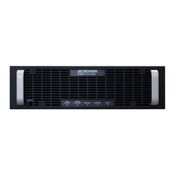
8302 OPERATOR’S MANUAL – SECTION 1 Figure 1.1 – 8302 Front Panel 1 Introduction Congratulations on your purchase of the 8302 Performance Overview digital power amplifier. 8302 amplifiers are 200Vp, low-noise, DC-to-50 kHz switch-mode amplifiers. Bandwidth DC - 50 kHz They are fast enough for DC automotive dropout testing and capable of AC voltages required for Voltage 0 to 140 V 0 to 200 VDC ISO 61000 and Aviation testing. Plus, they have low enough noise and distortion specifications to Current 65 A be the reference power source in power quality measurements. Distortion <0.2% 1.1 Features Power 2 kW Wide Bandwidth and Flexible Apparent Power 10 kVA The 8302 amplifier is capable of reproducing AC, ... -
Page 6: Amplifier Unpacking And Installation
8302 OPERATOR’S MANUAL – SECTION 2 2 Amplifier Unpacking and Installation 2.3 Installation The 8302 amplifier is a precision instrument that can be dangerous if not handled properly. Lethal The 8302 amplifiers are packaged in a rugged voltages are present in both the AC input supply powder-coated chassis. This chassis is 3U (rack and the output of the amplifier. For this reason, units) tall, and has rack “ears” on each side of the safety should be your primary concern when you front panel for mounting to a standard EIA (Elec- setup and operate this amplifier. tronic Industries Association) rack. Use standard rack mounting hardware to mount the ampli- 2.1 Safety First fier. Use nylon washers if you wish to protect the Throughout this manual special emphasis is powder-coat finish on the front of the amplifier. placed on good safety practices. The following Optionally, the amplifier can be placed on a graphics are used to highlight certain topics that bench top; please keep in mind that the protective require extra precaution. powder-coating can be scratched when placed on other equipment or on a bench top, especially WARNING when there is dirt present. To protect the finish, a set of rubber feet is included in the toolkit that can WARNING alerts you to hazards that be installed on the bottom of the amplifier. -
Page 7: Connecting The Load
8302 OPERATOR’S MANUAL – SECTION 3 Figure 3.1 – 8302 Back Panel are operating correctly. Once proper operation is Be sure to install the output safety cover after wir- ing the output connections. See Figure 3.3. confirmed, refer to the Applications section of this manual for instructions on configuring and operat- ing your amplifier in Controlled-Current mode. 3.1 Connecting the Load 3.1.1 Preparation and Cautions Before connecting the amplifier, make sure the AC power is disconnected. Always use the appropriate wire size and insula- tion for the maximum current and voltage expected at the output. Never connect the output of the amplifier to any other model amplifier, power sup- Figure 3.2 – Connecting the Load ply, signal source, or other inappropriate load; fire can result. WARNING ELECTRIC SHOCK HAZARD. -
Page 8: Other Dip Switch Settings
8302 OPERATOR’S MANUAL – SECTION 3 3.4 Monitor and Sense Ports The amplifier provides five additional back-panel ports: • Current Monitor (BNC connector) • Voltage Monitor (BNC connector) • Multi-amp Connectors (9-pin dSub connectors, two total) • Remote Sense Port (2-pin terminal block con- nector. See the Applications section of this manual for information on using these ports Figure 3.4 – Wiring for Unbalanced or Balanced WARNING Input Connector The back-panel DIP switch #1 can be used to en- The risk of lethal ELECTRICAL SHOCK able/disable the unbalanced input connector, and exists when connecting AC mains! Disconnect the source before connect- DIP switch #2 can be used to enable/disable the ... - Page 9 8302 OPERATOR’S MANUAL – SECTION 3 Do not disconnect or disable the protective grounding connection. Doing so causes a poten- tial electrical shock hazard. Connect the AC supply to the three-terminal bar- rier strip located on the amplifier back panel (see Figures 3.6 and 3.7). Install AC inlet cover prior to connecting to the sup- ply source. See Figure 3.8. Figure 3.6 – Closeup of AC Mains Barrier Strip for 120V or 230/240VAC wiring WARNING ELECTRIC SHOCK HAZARD. AC supply potentials can be lethal. Inlet cover must remain installed at all times to protect against HAZARDOUS LIVE VOLTAGES Start-up Procedure 1.
-
Page 10: Amplifier Operation
8302 OPERATOR’S MANUAL – SECTION 4 4 Amplifier Operation To release the amplifier from Standby mode: 1. High/Low Line error: Clear the over- or un- 4.1 Front-Panel Controls and Indicators der-voltage condition. The amplifier will resume This section provides an overview of Front-Panel operation when the input voltage is brought controls and indicators found on the 8302. Refer fo within the operating range of the amplifier. Figure 4.1 for component locations. 2. Overtemp condition: Remove the input signal 4.1.1 Power Switch from the amplifier and leave the amplifier with The Power switch controls the power to the ampli- the Power switch in the ON position and with fier’s high-voltage transformers. Switch to the ON the fans operating to cool the amplifier. When ... - Page 11 8302 OPERATOR’S MANUAL – SECTION 4 Overload (clipping): The indicator will flash when the temperature sensors detect a condition amber intermittantly. When the indicator flashes that would damage the amplifier. If the Overtemp amber, this indicates that the output of the system pulse is extremely short, as in the case of defec- could not follow the input signal due to voltage tive wiring or switches, this indicator may be lit too or current limits. The amber Overload indicator briefly to observe. will begin flashing when distortion is greater than To remove the amplifier from Standby and return 0.1%. it to normal operation after an Overtemp fault has occurred, make sure the Power switch is in the ON 4.1.4 High/Low Line Indicator position and the amplifier fans are running, and This amber indicator will illuminate and the ampli- then remove the input signal from the amplifier. Al- fier will be placed in Standby if the detected AC low the fans to run until the amplifier automatically mains voltage is outside of the operable range of returns to Run mode. See the Troubleshooting the amplifier (±10%). This can occur if the ampli- section for information on identifying and correct- fier’s back-panel breaker is not in the on position ing the cause of an Overtemp fault condition. (left), or if the AC supply into the amplifier is higher or lower than the operable range. 4.1.6 Fault Indicator To remove the amplifier from Standby, the AC The red Fault indicator will light and the amplifier ...
-
Page 12: Back-Panel Controls & Connectors
8302 OPERATOR’S MANUAL – SECTION 4 Voltage Monitor Connector – This unbalanced Back-Panel Controls & Connectors BNC port allows for connection to voltage monitor- This section provides an overview of Back-Panel ing equipment. The voltage monitor output is 1V = controls and connectors found on the 8302. Please 40V. refer to Figure 4.2 for component locations. Multi-amp Connectors – These two 9-pin D-sub AC Power Input – Three-terminal barrier strip connectors, labeled Interconnect A and Intercon- connector. nect B, can be used to connect two 8302 ampli- fiers in a Parallel or Push/Pull configuration. They Breaker – Protects the amplifier from voltage can also be used to set up a Safety Interlock circuit surge on the AC power input. to automatically place the amplifier in Standby Output Terminals – Connect output lines from the ... -
Page 13: Advanced Configuration
• Select and enable a synthetic impedance from • Select between two compensation networks for 0.125 ohms to 0.875 ohms. Controlled Current operation: CC1, designed 8302 Default DIP Switch Settings Red = Default DIP SWITCH SETTINGS DOWN 1 UNBALANCED INPUT 2 BALANCED INPUT 3 DC SERVO 4 OPERATION MODE 5 COMPENSATION NETWORK 2... -
Page 14: Dip Switch Configurations
5. Provide appropriate Compensation for the load, using this connector is disabled. Note that disabling an either Compensation Network 1 (SW#6) or Compensa- unused input connector can help to minimize noise tion Network 2 (SW#5). If neither compensation network is adequate for your load, contact AE Techron Technical going into the amplifier. Support. SW#2: Balanced Input 6. Turn off the amplifier immediately if oscillation oc- curs. - Page 15 DOWN position, a 30-Hz high-pass filter on the tions section of this manual. If neither of the avail- inputs prevents the transmission of DC signal. able RC networks is suitable for your application, SW#9 – SW#16: Gain please contact AE Techron Technical Support. The amplifier gain can be adjusted from 0.16 to 40 SW#6: Compensation Network 1 in increments of 0.16 using switches 9 through 16. When the 8302 amplifier is used in Controlled- All switches are additive and provide the following Current mode, the current control loop is tuned values toward the total Gain amount. with an RC network. The Compensation Network SW#9 = 20.00 SW#13 = 1.25 1 switch enables the factory default RC network. ...
-
Page 16: Custom Compensation
NOTE: If all four current-limit DIP switches are set Refer to Figure 5.2 for all available synthetic im- in the DOWN position, the amplifier’s output cur- pedance switch settings. rent will be limited to 10A. SW#21 - #24: Current Limit 5.2 Custom Compensation These four switches control the current-limit set- If you wish to change one of the two standard tings for the amplifier. When all four switches are compensations to a custom compensation, please in the UP position (default), the amplifier’s output contact AE Techron Technical Support for specific current is limited to 160A. The current-limit can be instructions. Information subject to change 96-8006123_11-03-2021... -
Page 17: Applications
8302 OPERATOR’S MANUAL – SECTION 6 6 Applications 6.2 Controlled-Voltage vs. Controlled- Current Modes of Operation 6.1 Emergency Standby Switch or AE Techron 8302 amplifiers can be field-configured Safety Interlock to operate as Voltage Amplifiers (Voltage-Con- The two 9-pin D-Sub connectors on the amplifier trolled Voltage Source) or as Transconductance back panel (Interlock A and Interlock B) can be Amplifiers (Voltage-Controlled Current Source). used to remotely place the amplifier in Standby The mode selection is made via the back-panel mode. This can provide a valuable safety feature, DIP switch #4. See the Advanced Configuration such as in creating a safety interlock for a cabinet section for more information. in which one or more 8302 amplifiers are installed When configured as a Controlled-Voltage source or wiring an emergency stop switch to the cabinet (voltage amplifier), the amplifier will provide an ... - Page 18 One of the two compensation settings that can be enabled with DIP switch settings will be sufficient Figure 6.3 – Input to Output Comparison, for most applications. If you determine that neither Controlled-Current Operation Compensation Network 1 or Compensation Net- work 2 will be adequate for your application and 6.2.1 Safety and Operation Consider- load, please contact AE Techron Technical Sup- ations for Controlled Current Operation port for additional compensation options. When an AE Techron amplifier is configured as a Controlled-Current source, care needs to be The following section describes methods for exercised in its operation. Any voltage controlled determining proper compensation setting for your current source should never be turned on application when operating in Controlled-Current ...
- Page 19 1 for your application. If your load inductance is between 1 mH and 5 mH, and your load resis- If your load inductance falls outside of these tance is less than 5 ohms, then you can likely use ranges, or if your load resistance is greater than Compensation Network 2 for your application. 5 ohms, please contact AE Techron Technical (See Figure 6.4). These compensation networks Support for assistance. Figure 6.4 – Selectable factory-installed compensation networks STEP 4: Verifying Operation After selecting and enabling your choice of Com- Remember the load you are connecting is a pensation Network, check to ensure that the ...
-
Page 20: Driving Reactive Loads
8302 OPERATOR’S MANUAL – SECTION 6 transition edges indicates compensation problems. To begin testing, input a square wave with a fre- (See Figure 6.5.) quency of 100 Hz to 1 kHz, or a squared pulse at a low level (typically 0.25 to 2.0 volts). A limited-rise- If a change in compensation is necessary, please time, repetitive pulse of low duty cycle is preferred. contact AE Techron Technical Support for as- sistance. DO NOT operate your amplifier in Con- Observe the output current through a current trolled Current mode without proper compensation. monitor or current probe. Look for clean transition edges. The presence of ringing or rounding on the Figure 6.5 – Compensation Effects on Waveform 6.3 Driving Reactive Loads While it is possible to operate a multi-amp system in either Controlled Voltage or Controlled Current Like all switching amplifiers, 8302 amplifiers are modes of operation, multi-amp operation in Con- able to reuse the energy returned from reactive trolled Current mode requires additional configura- loads. Unlike purely resistive loads, loads with tion of the equipment. Please contact AE Techron some reactance (either capacitive or inductive) will Tech Support for assistance with configuring a ... - Page 21 8302 Follower DIP Switch Settings Parallel Configuration 1 2 3 4 5 6 7 8 9 10 11 12 13 14 15 16 17 18 19 20 21 22 23 24 KEY FOR DIP SWITCH SETTINGS:...
- Page 22 8302 OPERATOR’S MANUAL – SECTION 6 2. Place the Follower amplifier on top of the tion of at least three digits. Both testing methods Master amplifier, and then connect the bus are provided below. bar (from the 8302 Multi-amp Kit) between the Testing Using an Oscilloscope GND output terminals of the Master and Fol- 1. Connect from a signal generator to the BNC or lower amplifiers. See Figure 6.8. WECO signal input connector on the back panel A. Remove the back-panel output covers from of the Master amplifier. Note that if the WECO both amplifiers. connector is used for signal input, DIP switch #1 B. Remove the 3/8-inch nuts from the GND on the Master amplifier should be placed in the terminals on both amplifiers. DOWN (OFF) position and DIP switch #2 should C. Install the bus bar across the GND termi- be placed in the UP (ON) position. nals of the Master and Follower amplifiers. 2. Turn down the level of your signal source. D. Replace the 3/8-inch nuts on both output 3. Make sure the back panel breaker switch on terminals. IMPORTANT: Torque the nuts both amplifiers is in the ON position, and then ...
- Page 23 0.5V, to build a “Y” cable with legs of equal length DO NOT complete the system setup. Contact (within 1/4-inch). IMPORTANT: The legs of AE Techron Technical Support for assistance. this output cable must be of equal length for proper system operation. See Figure 6.9. Testing Using a Floating Digital Multimeter Terminate each of the two legs of the cable ...
- Page 24 8302 OPERATOR’S MANUAL – SECTION 6 TWO 8302 AMPLIFIERS PARALLELED (CRITICAL WIRE LENGTHS) OUTPUT OUTPUT AMP #2 FOLLOWER OUTPUT OUTPUT AMP #1 MASTER Both wires of length “A” should be of the same length ±1/4 inch. Ÿ Wire lengths “A” and “B” may or may not be of the same length.
- Page 25 2. Connect the black (ground) output cable to the amplifier, continue with the system setup. ground terminal of your load. IMPORTANT: If current exceeds 2A (0.1V) 3. Connect “Y” end of the red (positive) output from either amplifier, DO NOT complete the cable to the positive terminal of your load. system setup. Contact AE Techron Techni- Refer to Figure 6.11 for completed system wiring. cal Support for assistance. 6.4.3 Push/Pull Multi-amp Configuration 8. Slowly raise the input voltage from 100 mV to To configure and connect two amplifiers for opera- to 2.5V while continuing to monitor current at ...
- Page 26 8302 OPERATOR’S MANUAL – SECTION 6 8302 Follower DIP Switch Settings Push/Pull Configuration 1 2 3 4 5 6 7 8 9 10 11 12 13 14 15 16 17 18 19 20 21 22 23 24 KEY FOR DIP SWITCH SETTINGS: 8302 Master DIP Switch Settings REQUIRED Push/Pull Configuration...
- Page 27 8302 OPERATOR’S MANUAL – SECTION 6 8302 PUSH/PULL SYSTEM 8302 AMPLIFIERS 8302 AMP #2 - FOLLOWER 1 2 3 4 5 6 7 8 9 10 11 12 13 14 15 16 17 18 19 20 21 22 23 24 AMPLIFIER OUTPUTS OUTPUT 8302 AMP #1 - MASTER...
- Page 28 8302 OPERATOR’S MANUAL – SECTION 6 mode (Run/Standby LED solid amber) and remain Overtemp: Both amplifiers monitors the tempera- in Standby mode until both amplifiers in the system ture inside its high-voltage transformers and in have been energized. The system will automati- the output stage heat sinks. The amber Overtemp cally proceed to Run mode when both amplifiers indicator will light and the system will be placed are energized and achieve Standby mode. in Standby mode when the temperature sensors in either amplifier detect a condition that would Switching the Power switch on either amplifier to damage the amplifier. If the Overtemp pulse is the OFF position will place both the amplifiers in extremely short, as in the case of defective wiring Standby mode. or switches, this indicator may be lit too briefly to observe. Signal/Overload Indicators When an input signal is presented to the Master To remove the system from Standby, make sure amplifier at a level greater than 0.5V, the Signal/ the fans in both amplifiers are running and then Overload indicators on both amplifiers will light remove the input signal from the system. Allow the solid green. When signal distortion greater than fans to run until the system automatically returns 0.1% is sensed by the Master amplifier, the Signal/ to Run mode. See the Troubleshooting section in Overload indicators on both of the amplfiers will ...
-
Page 29: Maintenance
8302 OPERATOR’S MANUAL – SECTION 7 7 Maintenance • Vacuum cleaner • Damp cloth (use water only or a mild soap Simple maintenance can be performed by the user diluted in water) to help keep the equipment operational. The fol- To ensure adequate cooling and maximum ef- lowing routine maintenance is designed to prevent ficiency of the internal cooling fans, the amplifier’s problems before they occur. See the Trouble- front and rear grills should be cleaned periodically. shooting section, for recommendations for re- To clean the amplifier grills and filter, complete the storing the equipment to operation after an error following steps: condition has occurred. 1. Disconnect the amplifier from its power source Preventative maintenance is recommended after via external mechanical disconnect or breaker. the first 250 hours of operation, and every three 2. The front grill is secured to the amplifier front months or 250 hours thereafter. If the equipment panel by magnets. Pull out on the grill to re- environment is dirty or dusty, preventative mainte- lease it from the front panel. nance should be performed more frequently. ... -
Page 30: Troubleshooting
8302 OPERATOR’S MANUAL – SECTION 8 8 Troubleshooting First, check to make sure the amplifier’s back- panel breaker is turned on. Next, check the voltage 8.1 Introduction & Precautions level of the AC supply. If the AC mains voltage is more than 10% outside the range of the operating This section provides a set of procedures for voltage, increase or reduce the AC mains voltage identifying and correcting problems with the 8302 to the proper level. When the line voltage condition amplifier. Rather than providing an exhaustive and is corrected, the amplifier will automatically return detailed list of troubleshooting specifications, this to Run mode. If the amplifier does not reset, the section aims to provide a set of shortcuts intended amplifier’s internal transformers may need to be to get an inoperative amplifier back in service as replaced. Please see the Factory Service infor- quickly as possible. mation at the end of this section. The procedures outlined in this section are direct- ed toward an experienced electronic technician; 8.5 Run/Standby LED Remains Amber it assumes that the technician has knowledge of ... -
Page 31: Fault Led Is Illuminated
Try resetting the Fault information at the end of this section. condition only once. If the Fault condi- tion does not clear after one reset, STOP. Contact AE Techron Support for further An OverTemp condition places the amplifier in assistance. Repeated resetting can dam- Standby mode. If the OverTemp pulse is ex- age the amplifier. - Page 32 8302 OPERATOR’S MANUAL – SECTION 8 Appendix A: Gain DIP Switch Settings Use this chart to determine the required settings switches ON = Gain of 39.85, all switches OFF = for DIP switches 9 through 16 to achieve the am- gain of 0 (signal will not be amplified). plifier gain you need for your application. Note: All ON = DIP Switch UP OFF = DIP Switch DOWN SW#9 SW#10 SW#11 SW#12 SW#13 SW#14 SW#15 SW#16 Gain 39.85 39.69 39.54 39.38 39.22 39.06 38.91 38.75 38.60 38.44 38.29 38.13 37.97 37.81 37.66 37.50 37.35 37.19 37.04...
- Page 33 8302 OPERATOR’S MANUAL – SECTION 8 ON = DIP Switch UP OFF = DIP Switch DOWN SW#9 SW#10 SW#11 SW#12 SW#13 SW#14 SW#15 SW#16 Gain 33.29 33.13 32.97 32.81 32.66 32.50 32.35 32.19 32.04 31.88 31.72 31.56 31.41 31.25 31.10 30.94 30.79 30.63 30.47 30.31 30.16 30.00 29.85 29.69 29.54 29.38 29.22 29.06 28.91 28.75...
- Page 34 8302 OPERATOR’S MANUAL – SECTION 8 ON = DIP Switch UP OFF = DIP Switch DOWN SW#9 SW#10 SW#11 SW#12 SW#13 SW#14 SW#15 SW#16 Gain 25.63 25.47 25.31 25.16 25.00 24.85 24.69 24.54 24.38 24.22 24.06 23.91 23.75 23.60 23.44 23.29 23.13 22.97 22.81 22.66 22.50 22.35 22.19 22.04 21.88 21.72 21.56 21.41 21.25 21.10...
- Page 35 8302 OPERATOR’S MANUAL – SECTION 8 ON = DIP Switch UP OFF = DIP Switch DOWN SW#9 SW#10 SW#11 SW#12 SW#13 SW#14 SW#15 SW#16 Gain 17.97 17.81 17.66 17.50 17.35 17.19 17.04 16.88 16.72 16.56 16.41 16.25 16.10 15.94 15.79 15.63 15.47 15.31 15.16 15.00 14.85 14.69 14.54 14.38 14.22 14.06 13.91 13.75 13.60 13.44...
- Page 36 8302 OPERATOR’S MANUAL – SECTION 8 ON = DIP Switch UP OFF = DIP Switch DOWN SW#9 SW#10 SW#11 SW#12 SW#13 SW#14 SW#15 SW#16 Gain 10.31 10.16 10.00 9.85 9.69 9.54 9.38 9.22 9.06 8.91 8.75 8.60 8.44 8.29 8.13 7.97 7.81 7.66 7.50 7.35 7.19 7.04 6.88 6.72 6.56 6.41 6.25 6.10 5.94 5.79...
- Page 37 8302 OPERATOR’S MANUAL – SECTION 8 ON = DIP Switch UP OFF = DIP Switch DOWN SW#9 SW#10 SW#11 SW#12 SW#13 SW#14 SW#15 SW#16 Gain 2.66 2.50 2.35 2.19 2.04 1.88 1.72 1.56 1.41 1.25 1.10 0.94 0.79 0.63 0.47 0.31 0.16 Information subject to change 96-8006123_11-03-2021...
Need help?
Do you have a question about the 8302 and is the answer not in the manual?
Questions and answers