
Related Manuals for AE Techron 8500 Series


Summary of Contents for AE Techron 8500 Series
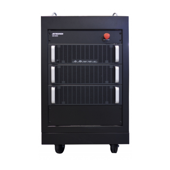
- Page 1 8500 Series Operator’s Manual Wide-Bandwidth, High-Power Digital Amplifiers Models 8508, 8512, 8516 and 8520 574.295.9495 | www.aetechron.com 2507 Warren Street, Elkhart, IN 46516...
- Page 3 This includes any damage to ITEMS EXCLUDED FROM WARRANTY another product or products resulting from such a This AE Techron Warranty is in effect only for failure defect. of a new AE Techron product which occurred within the Warranty Period.
-
Page 4: Table Of Contents
..........................5 1.2 Configuration Options......................5 2 Amplifier Unpacking and Installation ....................6 2.1 Safety First ..........................6 2.2 Unpacking ..........................6 2.3 Check Contents ........................6 2.4 8500 Series Placement ......................6 3 Connections and Startup .......................8 3.1 Testing Before Controlled-Current Operation ...............8 3.2 Connecting the Load ......................8 3.3 Connecting the Input Signal ....................9 3.4 Other DIP Switch Settings ....................9 3.5 Monitor and Sense Ports... -
Page 5: Introduction
Output Impedance: Variable from 0 to 1 ohm (Voltage mode) form types (AC, DC or AC+DC) at frequencies Sense: Sense line with correction of up to 4 • from DC to 50 kHz. Voltages from 0 to 250 VRMS volts are available with no changes in configuration. Reuses Energy from Reactive Loads Performance Overview The 8500 series excels when it comes to driv- DC - 50 kHz Bandwidth ing reactive loads. As frequencies increase, the effective-impedance of the load becomes a much Voltage 0 to 250 V RMS; 0 to 350 VDC larger part of the total load to be driven (especially ... -
Page 6: Amplifier Unpacking And Installation
Once again, note 1. Quick Start Guide the explanation of the hazard and the instructions for avoiding it. 2. 8500 series Operation Manual on USB drive 2.2 Unpacking 2.4 8500 Series Placement Your amplifier will be delivered to the ship-to ad- 8500 series amplifiers are mounted on wheels to dress enclosed in a wooden crate and transported allow rolling on a flat, smooth surface. To avoid on a special, shock-absorbing pallet. With the possible tipping, always push the amplifier from addition of packaging, the amplifier can weigh up ... - Page 7 8508 OPERATOR’S MANUAL – SECTION 2 Figure 2.2 – Clearance Recommendations for Amplifier Placement Information subject to change 96-8005549_3-18-21...
-
Page 8: Connections And Startup
Connection to the output of the amplifier is to a • Wait at least 3-5 minutes after pair of high-current output terminals located on disconnecting AC power before the amplifier back I/O panel. Wires terminated with opening the access door. • Wear safety goggles. 3/8-inch ring terminals are recommended when • Contact AE Techron Technical connecting to the output terminals. Connect the Support for any questions or load across the terminals marked “OUTPUT” (posi- concerns. tive) and “GND” (ground). The GND terminal also can be connected to an external ground point such as the amplifier chassis, if desired. See Figure 3.2. -
Page 9: Connecting The Input Signal
8508 OPERATOR’S MANUAL – SECTION 3 enabled. When the DIP switches are placed in the DOWN position, the input connectors are disabled. See Figure 3.4 for DIP switch locations. Figure 3.2 – Connecting the Load 3.3 Connecting the Input Signal Figure 3.4 – DIP Switch Locations for Both an unbalanced Input BNC jack and a bal- Input Connector Enable/Disable anced Input “WECO” terminal block connector (mating WECO connector provided) are available 3.4 Other DIP Switch Settings on the amplifier back I/O panel for signal input. Other DIP switches located on the amplifier mod- Connect your input signal source to the unbal- ule labeled “Master” can be used to enable fea- anced or balanced input connector as shown in tures or configure the amplifier for special applica- Figure 3.3. Use cables that are high quality and tions. See the Advanced Configuration section of shielded to minimize noise and to guard against ... - Page 10 8508 OPERATOR’S MANUAL – SECTION 3 Full AC requirements by product model are de- DANGER tailed below: The risk of lethal ELECTRICAL SHOCK MODEL 208V (±10%) 400V (±10%) exists when connecting AC mains! 30A, 50/60 Hz 30A, 50/60 Hz Disconnect the source before connect- 8508 ing AC power wires to the amplifier’s AC 30A, 50/60 Hz 30A, 50/60 Hz 8512 inputs.
-
Page 11: Start-Up Procedure
8508 OPERATOR’S MANUAL – SECTION 3 Figure 3.6 – Three-Phase AC Mains Wiring 3.7 Start-up Procedure 1. Turn down the level of your signal source. 4. Press the front-panel POWER switch to 2. Make sure the Emergency Stop button on turn the amplifier ON. the front panel is in the ON position (not 5. Wait until the Run/Standby indicator turns depressed). solid green. 3. Make sure the back panel access door is 6. Adjust your input signal level to achieve closed and the breaker switch (near the the desired output level. bottom of the amplifier rear) is in the ON position. Information subject to change 96-8005549_3-18-21... -
Page 12: Amplifier Operation
4 Amplifier Operation 1. High/Low Line error 2. Overtemp condition 4.1 Front-Panel Controls and Indicators 3. Fault condition This section provides an overview of Front-Panel 4. The user presses the front-panel power switch to the OFF (O) position. controls and indicators found on the 8500 series amplifier. Refer fo Figure 4.1 for component loca- In Standby mode, the amplifier’s low-voltage trans- tions. former is energized but the high-voltage transform- 4.1.1 Power Switch ers are not. The Power switch controls the power to the am- To release the amplifier from Standby mode:... - Page 13 8508 OPERATOR’S MANUAL – SECTION 4 cases where the amplifier’s transformers have If the High/Low Line indicator does not turn off or overheated, up to15 minutes of cooling time if the amplifier does not return from Standby, the may be required before the amplifier can re- amplifier may require servicing. See the Trouble- sume operation. See the Overtemp Indicator shooting section for more information. topic in this section for more information. 4.1.5 Overtemp Indicator 3. Fault condition: Press the front-panel power The amplifier monitors the temperature inside the switch to reset the amplifier. If the fault condi- high-voltage transformers and in the output stage tion recurrs or does not clear, the amplifier may heat sinks. The amber Overtemp indicator will light require servicing. See the Troubleshooting and the amplifier will be placed in Standby mode section for more information. when the temperature sensors detect a condition 4. Power switch pressed: When the amplifier is that would damage the amplifier. If the Overtemp operating (Run mode), pressing the front-panel pulse is extremely short, as in the case of defec- power switch will place the amplifier in Standby ...
-
Page 14: Back-Panel Controls & Connectors
8508 OPERATOR’S MANUAL – SECTION 4 Figure 4.2 – Back Panel Controls and Connectors Back-Panel Controls & Connectors Output Terminals – Connect output lines from the load to this pair of high-current output terminals This section provides an overview of Back-Panel using 3/8-inch ring terminals. controls and connectors found on the 8500 series amplifier. Please refer to Figure 4.2 for component Back-Panel Safety Features locations. This section provides an overview of Back-Panel Unbalanced BNC Input Connector – This input safety features found on the 8500 series amplifier. option provides a standard unbalanced input. Please refer to Figure 4.3 for component loca- tions. -
Page 15: Advanced Configuration
Controlled Current operation designed for loads To locate the Master amplifier module, disconnect from 1 mH to 5 mH. Install a custom compensation network for the amplifier from the AC source, and then open • Controlled Current operation. 8500 Series Default DIP Switch Settings, Master Amplifier Module Red = Default DO NOT CHANGE DIP SWITCH SETTINGS DOWN 1 UNBALANCED INPUT 2 BALANCED INPUT 3 DC SERVO... - Page 16 • Wait at least 3-5 minutes after (default), this connector is disabled. Note that disconnecting AC power before disabling an unused input connector can help to opening the access door. minimize noise going into the amplifier. • Wear safety goggles. • Contact AE Techron Technical SW#3: DC Servo Support for any questions or The DC Servo function ensures that no DC offset concerns. is present at the signal output (-3 dB at 3 Hz). Se- the amplifier back access door. The Master ampli- lect DC Servo when driving transformers or other ...
- Page 17 SW#7: Control Configuration pensation 2 network. For information on installing IMPORTANT: Do not change the Control Con- figuration switch on any 8500 series amplifier a custom compensation network, see Section 5.2 Master or Follower module unless instructed “Internal Configuration.” For more information by AE Techron Technical Support. Product on Controlled-Current operation, including instruc- failure could occur.
- Page 18 SW#17: Electronic Gain Matching IMPORTANT: Figure 5.3 – Synthetic Impedance Switch Do not change the Electronic Configurations Gain Matching switch on any 8500 series amplifier Master or Follower module unless instructed by AE Techron Technical Support. SW#21 - #24: Current Limit These four switches control the current-limit set- Product failure could occur.
-
Page 19: Applications
8508 OPERATOR’S MANUAL – SECTION 6 6 Applications 6.1 Controlled-Current Operation 6.1.1 Controlled-Voltage vs. Controlled- Current Modes of Operation AE Techron 8500 series amplifiers can be field- configured to operate as Voltage Amplifiers (Voltage-Controlled Voltage Source) or as Trans- conductance Amplifiers (Voltage-Controlled Figure 6.1 – Input to Output Comparison, Current Source). The mode selection is made via Controlled-Voltage Operation the back-panel DIP switch #4. See the Advanced Configuration section for more information. When configured as a Controlled-Voltage source (voltage amplifier), the amplifier will provide an output voltage that is constant and proportional to the control (input) voltage. If the load’s imped- ance changes, the amplifier will seek to maintain this ratio of input to output voltage by increasing or decreasing the current it produces, as long as it is within the amplifier’s ability to create the required Figure 6.2 – Input to Output Comparison, Controlled-Current Operation current. Use this mode if you want the output volt- age waveform to be like the input waveform (see ... - Page 20 8508 OPERATOR’S MANUAL – SECTION 6 with DIP switch settings will be sufficient for many taching a load before configuring your amplifier for applications, this compensation setting may also Controlled Current operation. This will allow you be adjusted in the field by installing a custom com- to verify that the input signal and the amplifier are pensation network. The following section describes operating correctly. methods for determining proper compensation Once this initial check is completed, power down requirements when operating in Controlled-Current the amplifier, attach your load, and move the mode. Operation Mode DIP switch (SW#4, located on the Master amplifier module’s back panel) to the 6.1.3 Controlling Compensation for CC Operation DOWN position to place the amplifier in CC mode. AE Techron 8500 series amplifiers can be config- STEP 2: Determine Required Compensation. ured for either Controlled Voltage (CV) or Con- When operating an amplifier in Controlled- trolled Current (CC) mode of operation. When Current mode, the load becomes an integral part operating the amplifier in Controlled Voltage (CV) of the system. In order to determine the required mode, compensation is not required. However, compensation for your load, consulting the follow- when operating in Controlled Current (CC) mode, ing table to determine the approximate compen- the amplifier load becomes an integral part of the sation capacitance (CC) required based on the ...
- Page 21 8508 OPERATOR’S MANUAL – SECTION 6 STEP 3: Enable Compensation Network low level (typically 0.25 to 2.0 volts). A limited-rise- time, repetitive pulse of low duty cycle is preferred. If your load inductance is between 75 μH and 1 mH, and your load resistance is less than 5 ohms, Observe the output current through a current then you can likely use Compensation Network monitor or current probe. Look for clean transition 1 for your application. If your load inductance is edges. The presence of ringing or rounding on the between 1 mH and 5 mH, and your load resis- transition edges indicates compensation problems. ...
-
Page 22: Driving Reactive Loads
8508 OPERATOR’S MANUAL – SECTION 6 If the output current waveform is neither under ters in the resistor location of the compensation damped or over damped, but the top of the square circuit because this can decrease stability and wave is not level, then you should instead de- may increase inductance. crease the capacitor value (see Figure 6.8). The parallel capacitor in the RC network serves • to increase stability but can be removed, if it is not required for system stability. If the parallel capacitor is used, it will usually decrease the value of resistance needed. In multiple amplifier systems, expect to decrease ... -
Page 23: Maintenance
• Wait at least 3-5 minutes after Using a vacuum cleaner, vacuum the area disconnecting AC power before around the amplifier modules and the back opening the access door. ventilation exit grill of each module. • Wear safety goggles. • Contact AE Techron Technical 7. Using a damp cloth, clean all amplifier mod- Support for any questions or ule’s rear ventilation grills. concerns. 8. Dry the front panels, back panels, filters, and grills with a clean cloth or allow to air dry. 7.1 Clean Amplifier Filter and Grills IMPORTANT: All parts should be completely 7.1.1 Tools Required... -
Page 24: Troubleshooting
AC power before luminated, check the following: opening the access door. • Wear safety goggles. 1. The AC mains are not connected or not on • Contact AE Techron Technical (see the Amplifier Setup section for more Support for any questions or concerns. information). ... -
Page 25: Run/Standby Led Remains Amber
8508 OPERATOR’S MANUAL – SECTION 8 amplifier’s internal transformers may need to be 8.7.2 Check for Inadequate Airflow 1. Check air filters. Over time they can become replaced. Please see the Factory Service infor- dirty and worn out. It is a good idea to clean mation at the end of this section. the air filters periodically with a mild detergent 8.6 Run/Standby LED Remains Amber and water. 2. Visually inspect fans to assure correct op- When the Run/Standby LED is lit solid amber, the eration while amplifier is On (I). When an amplifier is in Standby mode. Press the Power OverTemp fault occurs, the amplifier fans will switch to the ON position to place the amplifier in automatically be placed in continuous high- Run mode. speed operation. Any inoperative, visibly slow, or reverse-spinning fan should be replaced. If the amplifier does not return to run mode, check Please see the Factory Service information at to see if the High/Low Line, Overtemp, or Fault ... -
Page 26: Factory Service
Try resetting the Fault plifier for repair. It should be returned in its original condition only once. If the Fault condi- packaging or a suitable alternative. Replacement tion does not clear after one reset, STOP. Contact AE Techron Support for further packaging materials can be purchased from AE assistance. Repeated resetting can dam- Techron for a nominal fee. age the amplifier. - Page 27 8504 OPERATOR’S MANUAL – APPENDIX A Appendix A: Gain DIP Switch Settings Use this chart to determine the required settings switches ON = Gain of 39.85, all switches OFF = for DIP switches 9 through 16 to achieve the am- gain of 0 (signal will not be amplified). plifier gain you need for your application. Note: All ON = DIP Switch UP OFF = DIP Switch DOWN SW#9 SW#10 SW#11 SW#12 SW#13 SW#14 SW#15 SW#16 Gain 39.85 39.69 39.54 39.38 39.22 39.06 38.91 38.75 38.60 38.44 38.29 38.13 37.97 37.81 37.66 37.50 37.35 37.19 37.04 36.88 36.72...
- Page 28 8504 OPERATOR’S MANUAL – APPENDIX A ON = DIP Switch UP OFF = DIP Switch DOWN SW#9 SW#10 SW#11 SW#12 SW#13 SW#14 SW#15 SW#16 Gain 33.29 33.13 32.97 32.81 32.66 32.50 32.35 32.19 32.04 31.88 31.72 31.56 31.41 31.25 31.10 30.94 30.79 30.63 30.47 30.31 30.16 30.00 29.85 29.69 29.54 29.38 29.22 29.06 28.91 28.75 28.60 28.44...
- Page 29 8504 OPERATOR’S MANUAL – APPENDIX A ON = DIP Switch UP OFF = DIP Switch DOWN SW#9 SW#10 SW#11 SW#12 SW#13 SW#14 SW#15 SW#16 Gain 25.63 25.47 25.31 25.16 25.00 24.85 24.69 24.54 24.38 24.22 24.06 23.91 23.75 23.60 23.44 23.29 23.13 22.97 22.81 22.66 22.50 22.35 22.19 22.04 21.88 21.72 21.56 21.41 21.25 21.10 20.94 20.79...
- Page 30 8504 OPERATOR’S MANUAL – APPENDIX A ON = DIP Switch UP OFF = DIP Switch DOWN SW#9 SW#10 SW#11 SW#12 SW#13 SW#14 SW#15 SW#16 Gain 17.97 17.81 17.66 17.50 17.35 17.19 17.04 16.88 16.72 16.56 16.41 16.25 16.10 15.94 15.79 15.63 15.47 15.31 15.16 15.00 14.85 14.69 14.54 14.38 14.22 14.06 13.91 13.75 13.60 13.44 13.29 13.13...
- Page 31 8504 OPERATOR’S MANUAL – APPENDIX A ON = DIP Switch UP OFF = DIP Switch DOWN SW#9 SW#10 SW#11 SW#12 SW#13 SW#14 SW#15 SW#16 Gain 10.31 10.16 10.00 9.85 9.69 9.54 9.38 9.22 9.06 8.91 8.75 8.60 8.44 8.29 8.13 7.97 7.81 7.66 7.50 7.35 7.19 7.04 6.88 6.72 6.56 6.41 6.25 6.10 5.94 5.79 5.63 5.47...
- Page 32 8504 OPERATOR’S MANUAL – APPENDIX A ON = DIP Switch UP OFF = DIP Switch DOWN SW#9 SW#10 SW#11 SW#12 SW#13 SW#14 SW#15 SW#16 Gain 2.66 2.50 2.35 2.19 2.04 1.88 1.72 1.56 1.41 1.25 1.10 0.94 0.79 0.63 0.47 0.31 0.16 Information subject to change 96-8005549_2-4-21...
- Page 33 8504 OPERATOR’S MANUAL – APPENDIX B Appendix B: Amplifier Module Wiring Diagrams Information subject to change 96-8005549_2-4-21...
- Page 34 8504 OPERATOR’S MANUAL – APPENDIX B Information subject to change 96-8005549_2-4-21...
- Page 35 8504 OPERATOR’S MANUAL – APPENDIX B Information subject to change 96-8005549_2-4-21...
- Page 36 8504 OPERATOR’S MANUAL – APPENDIX B Information subject to change 96-8005549_2-4-21...
- Page 37 8504 OPERATOR’S MANUAL – APPENDIX B Information subject to change 96-8005549_2-4-21...
- Page 38 8504 OPERATOR’S MANUAL – APPENDIX B Information subject to change 96-8005549_2-4-21...
- Page 39 8504 OPERATOR’S MANUAL – APPENDIX B Information subject to change 96-8005549_2-4-21...
- Page 40 8504 OPERATOR’S MANUAL – APPENDIX B Information subject to change 96-8005549_2-4-21...
Need help?
Do you have a question about the 8500 Series and is the answer not in the manual?
Questions and answers