
Related Manuals for KT&C KPC-HDN722M


Summary of Contents for KT&C KPC-HDN722M
-
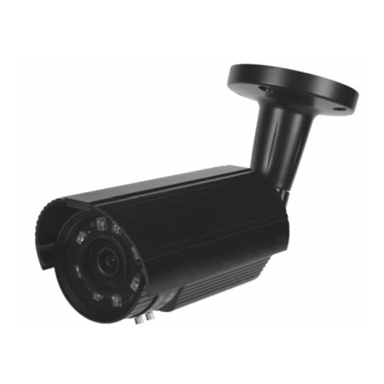
Page 1: Digital Video Camera
M161-HDN722-001 HD CCTV Digital Video Camera OPER ATI ON MA NUAL Thank you for choosing our high quality camera. Before attempting to connect operate this unit, please read and follow these instructions. - Page 2 CAU T ION These servicing instructions are for use by qualified service personnel only. To reduce the risk of electric shock do not perform any servicing other than that contained in the operating instructions unless you are qualified to do so. Use Class 2 Power Supply Only...
- Page 3 C O NT E NT S 1. CAUTIONS 2. IMPORTANT SAFETY INSTRUCTION 3. FEATURES 4. EQUIPMENT AND ACCESSORIES 5. INSTALLATION 6. DIMENSIONS 7. SPECIFICATION 8. OSD MANUAL...
- Page 4 1. CAUTIONS This device complies with Part 15 of the FCC Rules. Operation is subject to the following two conditions; 1. This device may not cause harmful interference. 2. This device must accept any interference received, including interference that may cause undesired operation. Note This equipment has been tested and found to comply with the limits for a Class A digital device, pursuant to part 15 of the FCC Rules.
- Page 5 1. CAUTIONS Correct Disposal of This Product (Waste Electrical & Electronic Equipment) (Applicable in the European Union and other European countries with separate collection systems) This marking shown on the product or its literature, indicate that it should not be disposed with other household wastes at the end of its working life. To prevent possible harm to the environment or human health from uncontrolled waste disposal, please separate this from other types of wastes and recycle it responsibly to promote the sustainable reuse of material resources.
-
Page 6: Important Safety Instruction
2. IMPORTANT SAFETY INSTRUCTION 1) Read these instructions. 2) Keep these instructions. 3) Heed all warnings. 4) Follow all instructions. 5) Do not use this apparatus near water. 6) Clean only with dry cloth. 7) Do not block any ventilation openings. Install in accordance with the manufacturer’s instructions. - Page 7 3. FEATURES • High Resolution SONY 1 / 3” 2.1M Progressive Color CMOS Image Sensor, 1080p(1920x1080)@30fps (Standard) • Support various digital video output 1080p@30fps, 1080p@25fps, 720p@60fps, 720p@50fps • Video Outputs Primary HD-SDI (BNC) Test/Setup TV Out (Test Point-adapter to BNC included) NTSC/PAL selectable •...
-
Page 8: Equipment And Accessories
4. EQUIPMENT AND ACCESSORIES H D C CTV D ig it al V id eo C a me ra S ERVI C E V I DEO OUT PU T T E ST CA B LE L WR E NC H O PE R A TIO N MA NU AL S CREW - 4ea... -
Page 9: Installation
5. INSTALLATION • CAMERA MOUNTING POSITION 360˚ PAN 90˚ TLIT 360˚ PAN 90˚ TLIT <Cable Concealed Thru Bracket>... - Page 10 5. INSTALLATION • External Zoom & Focus Adjustable The workmanship to adjust zoom and focus, opening the window cap might cause the humidity problems to the camera. The External Zoom and Focus system with out state-of-the- art technology provides easy camera installation without opening the window cap to adjust zoom and focus the lens.
-
Page 11: Monitor Connection
5. INSTALLATION • MONITOR CONNECTION RECEIVER DISPLAY DC12V / AC24V HD SDI IN DEVICE DC12V / AC24V REGULATED POWER SUPPLY RS485(+) RS485(-) VIDEO IN TEST CABLE HANDHELD MONITOR DC12V RECEIVER DISPLAY HD SDI IN DEVICE DC12V REGULATED POWER SUPPLY RS485(+) RS485(-) VIDEO IN TEST CABLE... - Page 12 6. DIMENSIONS DC12V / AC24V 98.6 Lens 168.6 High power LED Photo cell M15xP1.25 Ø110 DC12V 98.6 Lens 110.5 High power LED Photo cell M15xP1.25 Unit(mm) Ø95...
-
Page 13: Specification
7. SPECIFICATION Image Device 2.1 Mega Pixel, 1/3” Exmor CMOS Effective Pixels 1984 (H) x 1105 (V) Unit cell size 2.8um (H) x 2.8um (V) HD-SDI: 1080p@30fps, 1080p@25fps, 720p@60fps, 720p@50fps Video output mode TV Out: NTSC / PAL selectable Minimum illumination 0 Lux ( IR LED ON ) HD-SDI / 1.0 Vp-p Composite (75Ω) Video output... -
Page 14: Osd Manual
8. OSD MANUAL • Menu structure SETUP EXPOSURE WHITE BALANCE WDR / BLC IMAGE SPECIAL SYSTEN RESET DATA ALL EXIT Main Sub Menu Sub Menu BRIGHTNESS 0 ~ 20 AE MODE NORMAL AE / INDOOR LENS(IRIS) MANUAL / AUTO 1/30(25), 1/60(50), 1/120(100), 1/240, 1/500, LEVEL MANUAL / 1/1K, 1/2K, 1/4K, 1/8K, 1/16K, 1/30K, 1/60K. - Page 15 8. OSD MANUAL Main Sub Menu Sub Menu SHARPNESS 0 ~ 20 GAMMA 0 ~ 4 FLIP OFF, H FLIP, V FLIP, HV FLIP IMAGE LENS SHADING OFF, ON DZOOM 1x, 2x, 4x, 6x, 8x, 10x, 12x, 14x, 16x, 18x, 20x RESET DATA BACK / DEF.
-
Page 16: Function Description
8. OSD MANUAL • Function Description 0. SETUP - EXPOSURE : Go sub menu for camera exposure control. - WHITE ALANCE : Go sub menu for camera white balance control. - WDR / BLC : Go sub menu for camera WDR or BLC action. - DNR : Control noise reduction setting. -
Page 17: Display Info
8. OSD MANUAL - WDR WGT : WDR weight control level settig at WDR mode. - BLC OSD : Display BLC control zone in screen. - BLC POS-X : Select BLC control zone vertical position. - BLC POS-Y : Select BLC control zone horizontal position. - BLC SIZ-X : Select BLC control zone vertical size. - Page 18 8. OSD MANUAL 7. SYSTEM - COMM. ADJUST : RS-485 Communication Setting mode. • CAMERA ID. : RS-485 CAM ID Select. • BAUDRATE : RS-485 Communication Speed Select. • Apply & Exit : Apply all RS-485 Setting changed at once. Use the Set button to apply.
Need help?
Do you have a question about the KPC-HDN722M and is the answer not in the manual?
Questions and answers