
Related Manuals for KT&C KPC-LDD45NU


Summary of Contents for KT&C KPC-LDD45NU
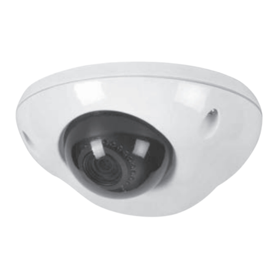
- Page 1 M176-LD(N)D45-001 HIGH PERFORMANCE WDR DOME CAMERA O P ER AT I O N M A N UA L Thank you for choosing our high quality camera. Before attempting to connect or operate this unit, please read and follow these instructions.
- Page 2 CO NTEN T S 1. CAUTIONS 2. IMPORTANT SAFETY INSTRUCTIONS 3. EQUIPMENT AND ACCESSORIES 4. CAMERA COMPONENT DESCRIPTIONS 5. INSTALLATION 6. DIMENSIONS 7. SPECIFICATIONS 8. OSD MANUAL • Menu Structure • Function Description C AU TI O N These servicing instructions are for use by qualified service personnel only. To reduce the risk of electric shock, do not perform any servicing other than that contained in the operating instructions unless you are qualified to do so.
- Page 3 1 . C AU TIONS This device complies with Part 15 of the FCC Rules. Operation is subject to the following two conditions: 1. This device may not cause harmful interference. 2. This device must accept any interference received, including interference that may cause undesired operation.
- Page 4 1 . C AU TIONS WEEE (Waste Electrical & Electronic Equipment) This marking shown on the product or its literature, indicates that it should not be disposed with other household wastes at the end of its working life. To prevent possible harm to the environment or human health from uncontrolled waste disposal, please separate this from other types of wastes and recycle it responsibly to promote the sustainable reuse of material resources.
-
Page 5: Important Safety Instructions
2 . IMPOR TANT SA FET Y INS TRUCTIONS 1) Read these instructions. 2) Keep these instructions. 3) Heed all warnings. 4) Follow all instructions. 5) Do not use this apparatus near water. 6) Clean only with dry cloth. 7) Do not block any ventilation openings. Install in accordance with the manufacturer’s instructions. -
Page 6: Equipment And Accessories
3 . EQUI PM ENT AND ACCES SORIES Dome Type Mount Guide Manual Screws(3ea) / L-Wrench Service Video Output Test Cable... -
Page 7: Camera Component Descriptions
4. CAMERA COMPONENT DESCRIPTIONS ➊ ➐ ➑ ➋ ➌ ➒ LED Type Standard Type ➍ ➓ ➎ PART NAME Housing Top Window Cover PCB ➏ PCB Module Rubber Case Housing Bottom Holder Middle Holder Top Ball Ass'y Holder Bottom Wave Water... -
Page 8: Installation
5 . IN STA L LATION 1. Attach the Camera to the ceiling with using the screws provided, taking into considering the camera angle required for the surveillance function. Template M4 Tappint Screw - 3EA 2. Adjust the LENS ANGLE to the desired location by hand. Rotate: ±180°... - Page 9 5 . IN STA L LATION 3. Connect the VIDEO OUT CABLE and check the video image. Change the SETTINGS accordingly using the OSD controller. Controller Test Video Connector Video Output Test Cable 4. After the SETTING is completed, install the TOP COVER. M4 Star Screw(T-20) L-Wrench(T-20)
- Page 10 5 . IN STA L LATION • MONITOR CONNECTION DC12V/AC24V POWER SUPPLY - DC12V/AC24V DC12V/AC24V (TERMINAL BLOCK) MONITOR VIDEO IN BNC FEMALE CAMERA DC12V ADAPTER DC12V - DC12V (DC JACK) MONITOR VIDEO IN BNC FEMALE CAMERA When you install the camera, please glue the end of cable to keep it stable in order to protect the camera from humidity problems.
- Page 11 6 . D IME N S IONS Ø120 Unit(mm)
-
Page 12: Specifications
7 . SPE CI FICAT IONS LED Type Standard Type Image Sensor 1/3” 960H SONY Double Scan Super HAD CCD II Scanning System 2 : 1 Interlace H Resolution. 750TV Lines Scanning Frequency NTSC: 15.734KHz(H), 59.94Hz(V) / PAL: 15.625KHz(H), 50Hz(V) Total Pixels No. - Page 13 8 . OS D MANUAL • Menu structure Main MENU 1st Sub MENU 2nd Sub MENU 3rd Sub MENU 4th Sub MENU 5th Sub MENU FLICKERLESS OFF / ON HIGH LUMINANCE BRIGHTNESS 0 ~ 255 OFF, AGC, SLOW, AGC->SLOW, MODE SLOW->AGC, AGC->SLOW->AGC AUTO LOW LUMINANCE...
- Page 14 8 . OS D MANUAL Main MENU 1st Sub MENU 2nd Sub MENU 3rd Sub MENU 4th Sub MENU 5th Sub MENU LEVEL 0 ~ 15 CONTRAST1 0 ~ 7 WDR MODE CONTRAST2 0 ~ 4 CENTER, TOP, BOTTOM, BLC ZONE LEFT, RIGHT WDR/BLC BLC MODE...
Need help?
Do you have a question about the KPC-LDD45NU and is the answer not in the manual?
Questions and answers