
Subscribe to Our Youtube Channel
Related Manuals for KT&C KPC-SPDN120HD


Summary of Contents for KT&C KPC-SPDN120HD
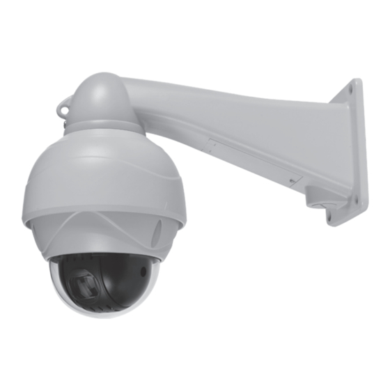
- Page 1 M136-SPDN120HD-002 HD CCTV 12X Optical Mini Speed Dome Camera OP ER ATIO N M ANUAL Before installing and using the camera, please read this manual carefully. Be sure to keep it handy for later reference.
-
Page 2: Table Of Contents
Contents Cautions IMPORTANT SAFETY INSTRUCTION 1. Overview 1 1 Features 1.2 System Configuration 1.3 Termination Settings 2. Installation and Connection 2.1 Package Contents 2.2 Installation 2.3 Connection Interface and Wiring Cables 2.4 Setting Dome Camera 3. Program and Operation OSD Menu Structure 3.1 Getting Started 3.2 Main Menu 3.3 System Setup Menu... -
Page 3: Cautions
Cautions This device complies with Part 15 of the FCC Rules. Operation is subject to the following two conditions; 1. This device may not cause harmful interference. 2. This device must accept any interference received, including interference that may cause undesired operation. Note This equipment has been tested and found to comply with the limits for a Class A digital device, pursuant to part 15 of the FCC Rules. - Page 4 Cautions Correct Disposal of This Product (Waste Electrical & Electronic Equipment) (Applicable in the European Union and other European countries with separate collection systems) This marking shown on the product or its literature, indicate that it should not be disposed with other household wastes at the end of its working life. To prevent possible harm to the environment or human health from uncontrolled waste disposal, please separate this from other types of wastes and recycle it responsibly to promote the sustainable reuse of material resources.
-
Page 5: Important Safety Instruction
IMPORTANT SAFETY INSTRUCTION Read these instructions. Keep these instructions. Heed all warnings. Follow all instructions. Do not use this apparatus near water. Clean only with dry cloth. Do not block any ventilation openings. Install in accordance with the manufacturer’s instructions. Do not install near any heat sources such as radiators, heat registers, stoves, or other apparatus (including amplifiers) that produce heat. -
Page 6: Overview
1. Overview 1.1 Features The PTZ Dome shall be quickly to install and be able to offer the services described in this document by way of an interface unit. Its mechanical architecture is designed to ensure adequate mechanical attachment to the wall of a dwelling. Details shall be provided as to how the PTZ Dome is to be installed. -
Page 7: System Configuration
1. Overview 1.2 System Configuration MULT IP LEXER 1.3 Termination Settings... -
Page 8: Installation And Connection
2. Installation and Connection 2.1 Package Contents Camera Wall Mount Bracket Operation Manual Screws/Plastic Anchors/Wrench/Washers /Terminal(AC24V,RS485 and Alram) Screws(4ea) Washers(4ea) Plastic Anchors(4ea) Terminal(AC24V) Terminal(RS485) Terminal(Alram) L-wrench... - Page 9 2. Installation and Connection Unit: mm Option - Ceiling Mount Bracket A-type B-type Option - Corner Mount Option - Parapet Mount Option - Pole Mount Strap Length 720...
-
Page 10: Installation
2. Installation and Connection 2.2 Installation Plastic anchors(4ea) Screws(4ea) ③ ② Washers(4ea) Safety Wire ① Connect the Camera Safety Wire to the Installation Base. -
Page 11: Connection Interface And Wiring Cables
2. Installation and Connection 2.3 Connection Interface and Wiring cables * Caution Do not connect the power cable until all other connections have been completed. After removing the protection sheet (PE form), supply the power to the dome camera. 2.3.1 Connecting the RS-485 lines The dome camera can be controlled remotely by an external device or control system such as a controller using RS-485 half duplexer (RS-485 Connection). -
Page 12: Setting Dome Camera
2. Installation and Connection 2.4 Setting Dome Camera The device can communicate with external switching device such as multiplexer or DVRs by setting the Rotary switch and Dip switch. Refer to tables below for setting the dome camera ID and protocol selection. Total length of the cable for communication should not exceed 1km. 2.4.1 Setting the address (ID) of dome camera To prevent wrong operation and malfunction, each dome camera has a unique address (ID). -
Page 13: Program And Operation Osd Menu Structure
3. Program and Operation [OSD Menu Structure] - Main Menu / Editing Title MAIN MENU TITLE S YST EM S ET UP D I SPL AY S ET UP ABCDEFGHIJKLMNOPQRSTUVWXYZ C AME RA S ET UP 0123456789/+-=:?!#.,"~() D O ME MO T I O N P RE SET SET U P P AT T ER N SE TU P SELECT: (MOVE) - Page 14 3. Program and Operation DOME MOTION SETUP GENERAL SETUP MOTION SETUP HOME ACTION CALIBRATION EXIT GENERAL SETUP MOTION SETUP HOME ACTION SETUP CALIBRATION SETUP POWER-UP ACT : ON PRO.PAN/TILT : ON ACTION : HOME AUTO CAL : AUTO MANUAL SPEED : 100DEG AUTO FLIP : ON NUMBER : ERROR MSG DISP : O N...
- Page 15 3. Program and Operation This manual is designed to be a reference for the programming and operation of the system. You can see information about features of the dome and commands as well as an operation method. The symbols below mean some action of the joystick controller. ▲...
-
Page 16: Getting Started
3. Program and Operation 3.1 Getting Started You should install and connect the dome to an interface device before using this operating guide. Refer to {2. Installation and connection of this manual}. Once installed, apply power to the dome and the start-up screen is displayed on the monitor. X 1 2 M INI S P E E D DO M E V x. -
Page 17: Main Menu
3. Program and Operation 3.2 Main Menu MAIN MENU SYS TE M S ET UP DI SP LAY SET U P CA MERA SET U P DO ME MO TI O N PR ESET SE TU P PAT T ER N S ET U P T O UR SET U P SC AN S ET UP ALA RM SE T UP... - Page 18 3. Program and Operation 3.3.2 Reboot REBOOT CO N T I NU E? YES : N EAR NO : F AR Reboot the system if there are some anomalous problems to control or operate the domes. Rebooting the system will recycle power of dome and camera without changing settings of dome. - Enter into {Main Menu} - Select {System) using joystick and move to {Reboot} in the sub menu of {System} - To {Reboot} the system, Press [Near] key.
-
Page 19: Display Setup Menu
3. Program and Operation 3.3.4 Entering a Password PASSWDRD CU R REN T : . . . EN ABL E : D I SA B L E NE W : . . . CO N F I RM : . . . 01 23 45 67 89 -SET / CL EAR : (TE L E / W I D E ) -EXI T : (F AR ) -
Page 20: Osd Setup
3. Program and Operation 3.4.2 OSD Setup OSD SETUP - TI TL E - M OD E - - D T IM E - LA B EL P OSI T I ON : O F F E R OO R M S G T I ME : ON - E X I T : FA R... -
Page 21: Image Setup
3. Program and Operation 3.4.4 Image Setup IMAGE SETUP MI R R O R : N O R M A L S AVE : O P E N B AC K : C LO S E This menu is for changing displayed image settings. - Enter into {Main Menu} - Select {Display} and move to {Image Setup} using joystick[▶]. -
Page 22: Camera Setup Menu
3. Program and Operation 3.5 Camera Setup Menu CAMERA SETUP F O C U S/ Z O O M W -BA LAN C E E XPO S UR E D AY / NI G H T A DV AN CED E XI T ▲... - Page 23 3. Program and Operation 3.5.2 WB Setup (White Balance Setup) WB SETUP MO DE : A WB R G AI N B G AI N S AVE : O P E N B AC K : C LO S E This feature automatically processes the viewed image to retain color balance over a color temperature range.
-
Page 24: Advanced Setup
3. Program and Operation 3.5.4 Day & Night Setup The Day & Night function improves the camera’s D/N SETUP sensitivity at night or when the brightness level of the ambient environment. According to the luminance level, D A Y / N I GH T : A U TO Day &... -
Page 25: Dome Motion Menu
3. Program and Operation 3.6 Dome Motion Menu DOME MOTION SETUP G ENE RA L SET U P MO TI O N SET U P H O ME A CT I O N C AL I BR AT I O N E XI T ▲... -
Page 26: Motion Setup
3. Program and Operation 3.6.2 Motion Setup MOTION SETUP P RO P . P AN / TI L T : ON A UT O F I LP : O N O VER TI L T : M OD E 1 S AVE : O P EN B AC K : CL O SE Proportional Pan / Tilt is possible to set manual speed with Zoom... -
Page 27: Preset Menu
3. Program and Operation 3.6.4 Calibration Setup CALIBRATION SETUP CONTINUE? Y E S : N E A R AUT O CA L : AU T O N O : FA R ERRO R MS G DI SP : O F F CAL I BRAT I ON REF RES H MO DE : O F F REF RES H T I ME :... -
Page 28: Pattern Menu
3. Program and Operation The dome has maximum 210 preset positions. Each of the user-defined presets includes Pan / Tilt / Zoom. Use the following steps to program {Preset}. PRESET SETUP P RE SS MO VE KE Y S AVE : N EAR B AC K : F A R - Enter into {Main Manu} - Select {Preset} and Move left or right to select Preset Number. -
Page 29: Tour Menu
3. Program and Operation Use the following steps to program {Pattern}. PTIME: 022 START POSITION SETUP PATTERN SETUP P RE SS MO VE KE Y S T ART : (NE AR ) S AVE : (N EAR ) E XI T : (F AR ) - Enter into {Main Manu} - Select {Auto Scan} and move left or right to select {Pattern} Number. -
Page 30: Auto Scan Menu
3. Program and Operation 3.10 Auto Scan Menu SCAN SETUP N O . 00 1 : N O T U S E D E DI T S PEE D D T I ME D I R ECT I O N : MO D E C L EAR S AVE : O PE N... -
Page 31: Alarm Menu
3. Program and Operation 3.11 Alarm Menu ALARM SETUP N O . 00 1 : N O T U S E D O U T PR I O R I TY AC T I O N N UMB ER D T I ME SA VE : O PE N BA CK : C LO S E - SET / C LE AR : (T E L E / W I DE ) -
Page 32: Troubleshooting Guide
4. Troubleshooting Guide If problems occur, check the installation of the dome with the instructions in this manual. And refer to this manual for further information. P r o bl e m So lut ion - Verify that power is connected to all components in the system. - Verify that the power switches are ON. -
Page 33: Specifications
5. Specifications Image Device 1/3" CMOS Effective Pixels About 2.1Mega Pixel HD: 1920*1080(Full HD, 1080p @30fps,25fps) 1280*720(HD, 720p @60fps,50fps,30fps,25fps) Video Signal SD: NTSC, PAL Lens 12X Optical /10X Digital Zoom (Auto Focus) View Angle Approx. Approx.52.4° (Wide end) to 4.64° (Tele end) Min. -
Page 34: Dimensions
6. Dimensions [Unit: mm] 341.2 Ø112 Ø120 Ø166.4 Ø138.4... -
Page 35: Appendix. Pelco Protocol Function List
APPENDIX. Pelco Protocol function List LCD Display Function Keys > F1(PSET), F2(TOUR), F3(PATT), F4(SCAN) ESC / Power Joystick Controller Camera Focus Control Number Function Keys > NER / FAR, TELE / WIDE Based on WTX1200A Function Preset No. Operation e.g. 1 e.g. -
Page 36: Camera Id Chart
Camera ID Chart S301 S302 S301 S302 S301 S302 S301 S302 S301 S302...
Need help?
Do you have a question about the KPC-SPDN120HD and is the answer not in the manual?
Questions and answers