Table of Contents

Subscribe to Our Youtube Channel
Related Manuals for KT&C KPC-HDN552MW


Summary of Contents for KT&C KPC-HDN552MW
- Page 1 M 1 5 3 - HD N5 5 2 - 0 0 1 HD CCTV Digital Video Super Night Vision Camera OPER ATI ON M ANUAL Thank you for choosing our high quality camera. Before attempting to connect operate this unit, please read and follow these instructions.
- Page 2 C AU T ION These servicing instructions are for use by qualified service personnel only. To reduce the risk of electric shock do not perform any servicing other than that contained in the operating instructions unless you are qualified to do so. Use Class 2 Power Supply Only...
- Page 3 C O NT E NT S 1 . CA UTIO NS 2 . IMPORTA NT SAF E T Y I N STR U CTI ON 3 . FEATURE S 4 . COMPONENT S 5 . NA ME AN D F UNCT I ON 6 .
- Page 4 1 . C AUT IO N S This device complies with Part 15 of the FCC Rules. Operation is subject to the following two conditions; 1. This device may not cause harmful interference. 2. This device must accept any interference received, including interference that may cause undesired operation.
- Page 5 1 . C AUT IO N S Correct Disposal of This Product (Waste Electrical & Electronic Equipment) (Applicable in the European Union and other European countries with separate collection systems) This marking shown on the product or its literature, indicate that it should not be disposed with other household wastes at the end of its working life.
-
Page 6: Important Safety Instruction
2 . IMP O R TA NT S A FE T Y I NS T RU C T IO N Read these instructions. Keep these instructions. Heed all warnings. Follow all instructions. Do not use this apparatus near water. Clean only with dry cloth. Do not block any ventilation openings. - Page 7 3 . F E AT U R E S • High Resolution SONY 1/3” 2.1 M Progressive Color CMOS Image Sensor, 1920x1080 30fps • Support various digital video output 720p60, 720p50, 1080p30, 1080p25 • Video Outputs Primary HD-SDI (BNC) Test / Setup TV Out (Test Point-adapter to BNC included), NTSC/PAL selectable •...
-
Page 8: N Ame A N D Fu Nc T I O N
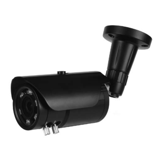
5 . N AME A N D FU NC T I O N ② ① ③ ⑥ ⑧ ⑤ ⑦ ⑤ ④ ① Sunsh iel d Fixin g Bo lt ② Sunsh iel d ③ Mo unti ng B ra cke t ④... -
Page 9: Installation
6 . INS TALL A TI O N • MOUNTING POSITION 360° 90° * 1st Axis * 2nd Axis WARNING ! To prevent injury, this apparatus must be securely attached to the floor/wall in accordance with the installation instructions. - Page 10 6 . INS T AL LA TI O N • MONITOR CONNECTION DC12V DC 12V POWER SUPPLY DC12V VIDEO IN MONITOR BNC FEMALE RS485 DUAL(DC12V / AC24V) DC 12V POWER SUPPLY or AC 24V POWER SUPPLY DC12V/AC24V VIDEO IN MONITOR BNC FEMALE RS485 When you install the camera, please glue up the end of cable to...
- Page 11 7 . D IM EN S I O N S Unit(mm) M15XP 1.25 Ø80...
-
Page 12: Specification
8 . SP ECI F I CA TI O N Image Device SONY 1/3” 2.1M Progressive Color CMOS Image Sensor Effective Pixels 1 9 8 4 (H) x 1 1 0 5 (V ) 3 0 f p s Unit cell size 2 . -
Page 13: Osd Menu Structure
9 . OS D M EN U S TR U C T U R E • Menu structure SETUP EXPOSURE WHITE BALANCE WDR / BLC DAY & NIGHT IMAGE SPECIAL SYSTEN Reset Date All Main Sub Menu Sub Menu BRIGHTNESS 0 ~ 20 AE MODE NORMAL AE / INDOOR... - Page 14 9 . OS D M EN U S TR U C T U R E Main Sub Menu Sub Menu SHARPNESS 0 ~ 20 GAMMA 0 ~ 4 FLIP OFF / H FLIP / V FLIP / HV FLIP IMAGE LENS SHADING OFF / ON DZOOM...
- Page 15 9 . OS D M EN U S TR U C T U R E • Function Description 0. SETUP - EXPOSURE : Go sub menu for camera exposure control. - WHITE BALANCE : Go sub menu for camera white balance control. - WDR/BLC : Go sub menu for camera WDR or BLC action.
- Page 16 9 . OS D M EN U S TR U C T U R E - BLC POS-X : Select BLC control zone vertical position. - BLC POS-Y : Select BLC control zone horizontal position. - BLC SIZ-X : Select BLC control zone vertical size. - BLC SIZ-Y : Select BLC control zone horizontal size.
- Page 17 9 . OS D M EN U S TR U C T U R E 8. SYSTEM - COMM. ADJUST : RS-485 Communication Setting mode. • CAMERA ID : RS-485 CAM ID Select. • BAUDRATE : RS-485 Communication Speed Select. •...
Need help?
Do you have a question about the KPC-HDN552MW and is the answer not in the manual?
Questions and answers