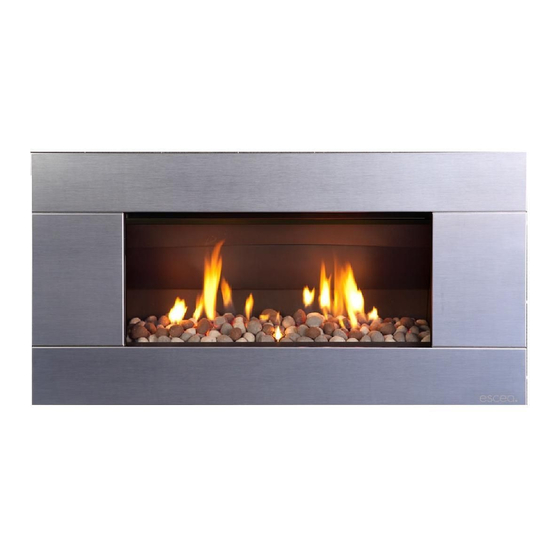
Escea ST900 Installation Manual
Direct vent gas fireplace
Hide thumbs
Also See for ST900:
- Installation manual (49 pages) ,
- User manual (18 pages) ,
- Manual (9 pages)
Table of Contents
Advertisement
Quick Links
ST900 Direct Vent Gas Fireplace
Installation Manual
NZ / AUS EDITION
Important:
The appliance shall be installed in accordance with;
• This installation instruction booklet
• Local gas fitting regulations
• Municipal building codes
• Electrical wiring regulations
• AS/NZS 5601, Gas installations
• Any other relevant statutory regulations.
• Must be installed by a qualified person
FOR SERIAL NUMBERS 43000 AND ABOVE.
Manufactured by: Escea Ltd, PO Box 5277 Dunedin New Zealand,
Ph: +64 3 478 8220, email:
info@escea.com
www.escea.com
630292_0_ AUS NZ Installation Manual
1
Advertisement
Table of Contents

Subscribe to Our Youtube Channel
Related Manuals for Escea ST900


Summary of Contents for Escea ST900
- Page 1 • AS/NZS 5601, Gas installations • Any other relevant statutory regulations. • Must be installed by a qualified person FOR SERIAL NUMBERS 43000 AND ABOVE. Manufactured by: Escea Ltd, PO Box 5277 Dunedin New Zealand, Ph: +64 3 478 8220, email: info@escea.com www.escea.com...
- Page 2 Gas pipe placement to the front left of the cavity. • The ST900 electronic control system is designed to work within the temperature range of 0°C to 80°C without batteries and 0°C to 60°C with batteries, with a humidity level that is non condensing.
- Page 3 Installation must be carried out by a registered installer who, on completion of the installation, must issue a certificate of compliance, in accordance with national and/or local codes. If a certificate of compliance is not issued then the Escea warranty may be void. Warranty Repair and Annual Servicing: Warranty repair work must be carried out by a recognised Escea gas fire technician.
-
Page 4: Product Specification
630292_0_ AUS NZ Installation Manual PRODUCT SPECIFICATION MODEL NAME ST900 Description of Appliance Decorative Gas Fire Star Rating A/NZ Approval No. AS 4558-2011 & NZS/AS4558-2013 Gas Type Natural ULPG Propane High 18 MJ/h 21 MJ/h 21 MJ/h Gas input (MJ/h) 12.9 MJ/h... - Page 5 630292_0_ AUS NZ Installation Manual Recommended Installation Process: The following diagram illustrates the steps required to install your gas fire, and the trades required at each stage. The sequence in which you choose to do these tasks will vary depending on your individual scenario.
-
Page 6: Table Of Contents
630292_0_ AUS NZ Installation Manual Contents: Product Description Creating the Cavity Hearth and Floor Clearances Wall Linings Vertical Clearances Corner Installations Laying Gas Pipe Connecting Gas Pipe Power Supply 10.0 Fixing Fire to Wall 11.0 Removing the Firebox Glass 12.0 Installing the Flue system 13.0 Fitting the Flue Restrictor... -
Page 7: Product Description
The cavity specifications vary depending on fascia type. The dimensioned drawings in the following sections show the size of opening that must be created to fit the ST900. The wall directly above the fire should be finished / gibbed / lined after the fire has been installed, unless there is an access hatch or the chase is open to the ceiling cavity, which allows the flue to be installed after the wall has been lined. -
Page 8: Hearth And Floor Clearances
Hearth and Floor Clearances: There should be at least 100mm between the bottom of the ST900 fire and any horizontal surface below, for example hearths and floors. Wall and Cabinet Clearances: There must be a minimum of 100mm from the sides of the fascia to any protruding side walls or cabinetry. -
Page 9: Wall Linings
The drawings below are suggestions that may be used as a GUIDE for those consumers who do decide to locate their TV above an ST900 gas fire. These drawings show ways to reduce the amount of warm air rising off the fireplace and onto the TV. -
Page 10: Corner Installations
ST900. Note: Escea does not recommend placement of items on the mantles shown in the diagram to the right. This is because of the potential for items placed on or above the mantle to be affected by the heat rising from the appliance. -
Page 11: Connecting Gas Pipe
630292_0_ AUS NZ Installation Manual Connecting the Gas Pipe: Copper should be run directly to the fireplace and connected onto the Dormont hose with a 1/2” BSP thread nut. Cavity Cavity Cavity S 900 S 900 Alternate gas supply route Power Supply: Your fireplace has been supplied with a transformer and a battery back-up provision- 4 x AA Cells;... -
Page 12: Removing The Firebox Glass
630292_0_ AUS NZ Installation Manual 10.0 Fixing the Fire to the base and wall: It is a requirement that this fire be securely fastened to the wall and base. Once the fire has been pushed back into the correct position, use wood screws (or other suitable fasteners) to fix the fire to the cavity through each of the four holes in the corners, as shown in the diagram to the... -
Page 13: Installing The Flue System
630292_0_ AUS NZ Installation Manual 12.0 Installing the Flue System: Ensure all flue components are Simpson Duravent Direct Vent Pro 5” x 8,” no other flue types may be used. Note: Consult section 12.13 to ensure correct length of flue is calculated. There are two basic types of Balanced Flue System installations: 280.0 •... - Page 14 630292_0_ AUS NZ Installation Manual 12.5 Vertical Only Flue Diagram: Use this diagram to determine what percentage of flue restriction in required to ensure safe and correct operation of the ST900 decorative gas fireplace.
- Page 15 630292_0_ AUS NZ Installation Manual 12.6 Horizontally Terminating Flue Diagram: Use this diagram to determine what percentage of flue restriction in required to ensure safe and correct operation of the ST900 decorative gas fireplace.
- Page 16 630292_0_ AUS NZ Installation Manual 12.7 Vertically Terminating flue with a Horizontal Offset: Use this diagram to determine what percentage of flue restriction in required to ensure safe and correct operation of the ST900 decorative gas fireplace.
- Page 17 630292_0_ AUS NZ Installation Manual 12.8 Standard Flueing Configurations: The following flue components are available from escea in kitset form. DVF-H DVF-V...
- Page 18 630292_0_ AUS NZ Installation Manual 12.9 Locating the Flue Terminal: The flue terminal must be located using the information given in the following diagram and table based on AS/NZS 5601...
- Page 19 630292_0_ AUS NZ Installation Manual Table 16 – Minimum clearances required for flue terminals shown in figure 3 Ref. Item Minimum Clearances (mm) Natural draught assisted Below eaves, balconies and other projections: Gas appliances up to 50 MJ/h input Gas appliances over 50 MJ/h input From the ground, above a balcony or other surface (see note 6) From a return wall or external corner (see note 6) From a gas meter (M) (see 2.5.4.9 for vent terminal location of...
- Page 20 630292_0_ AUS NZ Installation Manual 12.11 Sealing ‘through roof’ and ‘through wall’ penetrations: For ‘through roof’ penetrations, use a Deck-tite flashing or equivalent to create a weather- tight seal between the flue and the roof cladding. For ‘through wall’ penetrations, this will require the use of a Wall Thimble. The Wall Thimble will ensure you have suitable clearance from combustibles as well as sealing the penetration.
- Page 21 630292_0_ AUS NZ Installation Manual 12.13 Points to note when planning the Installation of the Escea DV flue: This flue system cannot be cut to length. Correct lengths must be selected for each installation. For a full list of available flue lengths, contact your Escea retailer.
-
Page 22: Fitting The Flue Restrictor
630292_0_ AUS NZ Installation Manual 13.0 Fitting the Flue Restrictor: If your flueing configuration requires that you fit a flue restrictor (see graph in section 12.5, 12.6 & 12.7 of this manual to find out if your configuration requires a flue restrictor), follow the instructions below. -
Page 23: Converting To Ulpg Or Propane
630292_0_ AUS NZ Installation Manual 14.0 Converting to ULPG or Propane: This fire has been supplied & configured for Natural Gas; where a conversion to ULPG or Propane is needed, the following steps should be followed. 14.1 First you need to remove the burner by removing the screw holding it in place on the left hand side of the firebox (Fig. -
Page 24: Changing Operating Pressure To Ulpg/Propane
Check all connections and pressure taps for leaks. The sticker must be signed and dated by the installer who has converted the fire. The ST900 dataplate is located in the lower left of the fireplace, on a metal plate tethered to the fireplace. -
Page 25: Placing The Fuel Bed Media
630292_0_ AUS NZ Installation Manual 16.0 Placing the Fuel Bed Media: Your ST900 Gas fire will be supplied with a Fuel Bed kit. Follow the instructions below for the Fuel Bed kit that applies to you. USE only fuel bed media approved by Escea. -
Page 26: Covering Up The Fire
630292_0_ AUS NZ Installation Manual 17.0 Covering up the fire: Before the wall surrounding the ST900 is lined, the fire must be covered up and sealed to prevent Gib dust from getting into the fire. It is recommended that the packaging supplied with the fire is used to achieve this. - Page 27 The perforated surface (grill) should be on top. The ST900 fascia uses these four hooks for attaching to the fire. Do this by lining up the fascia hooks with the receptacles on the sides of the fire.
- Page 28 Install the lower fascia magnet brackets using the 4x supplied screws in the two positions shown below. (Do not affix the magnets at this stage) Installation: The ST900 fascia uses the hooks on the rear for attaching to the fire. Line up the hooks with the receptacles on the sides of the fireplace, and lift the fascia so that the hooks are above the receptacles.
- Page 29 630292_0_ AUS NZ Installation Manual 18.4 Cleaning the ST900 Fascia: The fascia must be cold before starting any form of maintenance or cleaning. If your Stainless Steel fascia requires cleaning, 3M Stainless Steel cleaner (or equivalent) is recommended. If your Powder Coated (Painted) fascia requires cleaning, you must only use a damp non- abrasive cloth to give it a gentle wipe.
-
Page 30: Remote Instructions
630292_0_ AUS NZ Installation Manual 19.0 Remote Instructions 19.1 Pairing the Remote to the Control Unit: The remote supplied is already paired with the receiver (control) unit in the factory. Use the following only when required: 1. Press and hold the receiver’s reset button (refer to section 23.0 for location) until you hear two beeps. -
Page 31: Annual Service Check
630292_0_ AUS NZ Installation Manual 21.0 Annual Service Check The ST900 Fireplace should be serviced annually to ensure it continues to operate in a safe manner. This annual service check should involve the following x Check thermocouple holds the cartridge... -
Page 32: Wiring Diagram
630292_0_ AUS NZ Installation Manual 23.0 Wiring Diagram: Main Burner 8 Wire Cable Pilot Burner GV60 Valve hermocurrent Cable W Interrupter Block hermocurrent Cable C Membrane S witch Ignition Cable Receiver Reset Button Power Supply...
Need help?
Do you have a question about the ST900 and is the answer not in the manual?
Questions and answers