Escea ST900 Installation Manual
Direct vent gas fireplace
Hide thumbs
Also See for ST900:
- Installation manual (48 pages) ,
- User manual (18 pages) ,
- Manual (9 pages)
Table of Contents
Advertisement
Quick Links
ST900 Direct Vent Gas Fireplace
Installation Manual
NORTH AMERICA EDITION
WARNING: If the information in these
instructions are not followed exactly, a fire or
explosion may result causing property
damage, personal injury or loss of life.
Do not store or use gasoline or other flammable
vapors and liquids in the vicinity of this or any
other appliance.
WHAT TO DO IF YOU SMELL GAS
Do not try to light any appliance.
Do not touch any electrical switch do not
use any phone in your building.
Immediately call your gas supplier from a
neighbors phone. Follow the gas suppliers
instructions.
If you cannot reach your gas supplier, call
the fire department.
Installation and service must be performed by a
qualified installer, service agency, or the gas
supplier.
INSTALLER: Leave this manual with the appliance.
CONSUMER: Retain this manual for future reference.
Ce manual est disponsible en Français sur demande.
www.escea.com
Manufactured By: Escea International Limited, 375b Green Valley Road, Griffen, GA 30224 USA. Ph: 866 615 3096 |
630167_3_Manual_Installation_US_R emotion
This appliance may be installed as an OEM
installation in a manufactured home (USA
only) or mobile home and must be installed
in accordance with the manufacturer's
instructions and the Manufactured Home
Construction and Safety Standard, Title 24
CFR, Part 3280, in the United States, or the
Standard for Installation in Mobile Homes,
CAN/CSA Z240 MH, in Canada.
This appliance is only for use with the types
of gas indicated on the rating plate. A
conversion kit is supplied with the
appliance.
This appliance may be installed in an
aftermarket, permanently located,
manufactured home (USA only) or mobile
home, where not prohibited by local codes.
This appliance is only for use with the types
of gas indicated on the rating plate. A
conversion kit is supplied with the
appliance.
info@escea.net
Advertisement
Table of Contents

Subscribe to Our Youtube Channel
Related Manuals for Escea ST900


Summary of Contents for Escea ST900
- Page 1 CONSUMER: Retain this manual for future reference. Ce manual est disponsible en Français sur demande. appliance. www.escea.com Manufactured By: Escea International Limited, 375b Green Valley Road, Griffen, GA 30224 USA. Ph: 866 615 3096 | info@escea.net...
- Page 2 • Converting this appliance for use with other gasses must be done by a qualified installer, service agency, or gas supplier Warning: Due to high temperatures, the ST900 should be located out of traffic and away from furniture and draperies. The area around the ST900 MUST be kept clear and free from combustible materials, gasoline and other flammable vapors and liquids.
- Page 3 630167_3_Manual_Installation_US_R emotion Note: THERE ARE A FEW THINGS TO CONSIDER BEFORE INSTALLATION • Cavity Dimensions and Clearances • MUST be installed a minimum of 4” above the floor or nearest horizontal surface. • Coupling of flue to fireplace • Gas pipe placement to the front left of the cavity. •...
-
Page 4: Table Of Contents
Installation must be carried out by a registered installer who, on completion of the installation, must issue a certificate of compliance, in accordance with national and/or local codes. If a certificate of compliance is not issued then the Escea warranty may be void. Warranty Repair and Annual Servicing: Warranty repair work must be carried out by a recognised Escea gas fireplace service agency. -
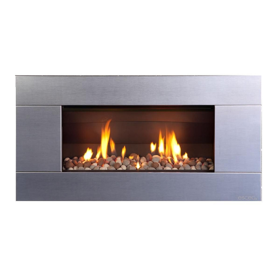
Page 5: Product Description
The dimensioned drawing below shows the size of opening that must be created to fit the ST900. The wall directly above the fireplace should be finished / clad / lined after the fireplace has been installed, unless there is an access hatch or the chase is open to the ceiling cavity, which allows the flue to be installed after the wall has been lined. -
Page 6: Hearth And Floor Clearances
630167_3_Manual_Installation_US_R emotion Hearth and Floor Clearances: There should be at least 4” clearance between the bottom of the ST900 fireplace and any horizontal surface below, for example hearths and floors. Wall and Cabinet Clearances: There must be a minimum of 4” clearance from the sides of the fascia to any protruding side walls or cabinetry. - Page 7 ST900. Note: Escea does not recommend placement of items on the mantles shown in the diagram to the right. This is because of the potential for items placed on or above the mantle to be affected by the heat rising from the appliance.
-
Page 8: Corner Installations
ST900 = 19,500 BTU/h max on Natural Gas High Altitude Installations When installing this appliance at an elevation above 2000 feet, it may be necessary to decrease the input rating by changing the existing burner orifice to a smaller size. -
Page 9: Power Supply
630167_3_Manual_Installation_US_R emotion Battery-Pack Power Supply: The ST900 runs on a battery pack. This battery pack uses 3x C cell batteries. To ensure that only fresh batteries are used, batteries are not supplied with the fireplace. To access the battery pack, remove the fascia (described in section 11.0) and the battery pack will be on the lower right hand side. -
Page 10: Installing The Flue System
630167_3_Manual_Installation_US_R emotion 12.0 Installing the Flue System: Ensure all flue components are Simpson Duravent Direct Vent Pro 5” x 8,” or a compatible equivalent. Note: Consult Appendix A at the end of this installation manual (section 24.0) to ensure correct length of flue is calculated. There are two basic types of Balanced Flue System installations: •... - Page 11 630167_3_Manual_Installation_US_R emotion 12.5 Vertical Only Flue Diagram: Use this diagram to determine what percentage of flue restriction is required to ensure safe and correct operation of the ST900 Direct Vent Decorative Gas Fireplace. See Section 13.0...
- Page 12 630167_3_Manual_Installation_US_R emotion 12.6 Horizontally Terminating Flue Diagram: Use this diagram to determine what percentage of flue restriction is required to ensure safe and correct operation of the ST900 Direct Vent Decorative Gas Fireplace. See Section 13.0...
- Page 13 630167_3_Manual_Installation_US_R emotion 12.7 Vertically Terminating flue with a Horizontal Offset: Use this diagram to determine what percentage of flue restriction is required to ensure safe and correct operation of the ST900 Direct Vent Decorative Gas Fireplace. See Section 13.0...
- Page 14 630167_3_Manual_Installation_US_R emotion 12.8 Standard Flueing Configurations: The following flue components are available from your escea distributor/retailer in kitset form. DVF H DVF V...
- Page 15 630167_3_Manual_Installation_US_R emotion 12.9 Locating the Flue Terminal: The flue terminal must be located using the information given in the following excerpt from ANSI Z21.88-2005 Vented Gas Fireplace Fireplaces.
- Page 16 630167_3_Manual_Installation_US_R emotion 12.10 Supporting the flue system: Wall straps are required to fix the flue system in place for each installation. This will ensure that no undue strain is placed on flue components once installed. For a flue offset or horizontal run, it is recommended that wall straps be used to the flue system with a spacing of 3’...
-
Page 17: Fitting The Flue Restrictor
630167_3_Manual_Installation_US_R emotion 13.0 Fitting the Flue Restrictor: If your flueing configuration requires that you fit a flue restrictor (see graph in section 12.5, 12.6, 12.7 of this manual to find out if your configuration requires a flue restrictor), follow the instructions below. -
Page 18: Converting To Propane Gas
630167_3_Manual_Installation_US_R emotion 14.0 Converting to Propane Gas: Where a conversion to propane gas is needed, the following steps should be followed 14.1 First you need to remove the burner by removing the screw holding it in place on the left hand side of the firebox (Fig. 1). Then remove the 1.9mm burner jet (Fig. - Page 19 Now, put the gas data (Propane sticker shown) ST900 sticker supplied in the conversion kit in onto the Edition dataplate of the ST900 in the position shown. Note: This will need to be completed on the English language as well as the French language dataplates. (English language...
-
Page 20: Placing The Fuel Bed
630167_3_Manual_Installation_US_R emotion 15.0 Placing the Fuel Bed Media: Your ST900 Gas fireplace will be supplied with a Fuel Bed kit. Follow the instructions below for the Fuel Bed kit that applies to you. 15.1 Driftwood Fuel Bed: First scatter one layer of the supplied white stones evenly across the base of the firebox, ensuring there are no stones or driftwood pieces inside the pilot flame surround guard. -
Page 21: Re-Fitting The Glass Assembly
To clean the glass, remove it as described in section 11.0 and clean inside and out using standard window cleaner. Do not allow glass to become excessively dirty as this will be difficult to remove. If you require a replacement glass assembly one is available through escea retailers or dealers using the product code: 802207 WARNING: DO NOT ATTEMPT TO CLEAN THE GLASS WHILE IT IS HOT. -
Page 22: Checking Operating Pressure
Checking Operating Pressure: WARNING: The regulator that is supplied with the fireplace MUST NOT BE REMOVED. Removal of the regulator, or replacing it with one not intended for use with an Escea fireplace, will void the limited appliance warranty. This is done at the regulator located at the front LH corner of the appliance. -
Page 23: Covering Up The Fireplace
‘Escea’ logo on the front]. The ST900 fascia uses these four hooks for attaching to the fireplace. Do this by lining up the fascia hooks with the receptacles on the sides of the fireplace. Lift the fascia so that the hooks are above the receptacles, and let it drop down into position until it is secure and free from movement. - Page 24 19.3 Cleaning the ST900 Fascia: The fascia must be cold before starting any form of maintenance or cleaning. If your Stainless Steel fascia requires cleaning, 3M Stainless Steel cleaner (or equivalent) is recommended.
-
Page 25: Operating Instructions
630167_3_Manual_Installation_US_R emotion 20.0 Operating Instructions:... - Page 26 Switching on the ST900: Note: If this is the first time running the ST900 the air will need to be purged from the gas lines. To do this, follow the instructions below to switch the fire on and then switch it off.
- Page 27 630167_3_Manual_Installation_US_R emotion 19.4 Switching off the ST900: To turn off the fire, push the OFF button, to shut down the gas flow to the fire and switch it off. The OFF display will now appear in the display. 19.5 Setting the control mode for the fireplace: There are three different modes for controlling the appliance: >...
- Page 28 630167_3_Manual_Installation_US_R emotion > Program mode: By default the program mode is not enabled. To enable program mode, enter configuration mode by pressing and holding the OFF button for 40 seconds, selecting “Programming” and selecting “yes” (For more information on configuration mode see section 19.9). There are two types of program mode: a Daily mode and a Weekly mode.
- Page 29 Similarly, if ‘Flame Down’ is pressed while the unit is in the ‘pilot’ flame position, nothing will happen. To shut down the gas flow to the ST900, press the On/Off button and the LED will begin to blink and the unit will emit a beep.
- Page 30 630167_3_Manual_Installation_US_R emotion 19.10 Pairing the Remote to the Control Unit: Install batteries to the battery pack and after a while the valve motor will start moving (if not wait one minute from the time of installing batteries). Once the valve has finished moving, press the OFF button on the remote control for 40 seconds.
- Page 31 630167_3_Manual_Installation_US_R emotion 19.11 Initial configuration: To enter the configuration menu, press the OFF button on the remote control for 40 seconds. During this time the screen may go blank, this is normal. After 40 seconds, the configuration menu appears. It is possible to configure the appliance with the following options: Thermostat: This option enables or disables the auto thermostat mode.
-
Page 32: Sounds And Smells
630167_3_Manual_Installation_US_R emotion 21.0 Sounds and Smells: Note: Each time the fireplace is lit from cold the glass will fog up with condensation. This is normal and the condensation will disappear within a few minutes once the glass heats up. 21.1 Sounds: It is possible that you will hear some sounds from your gas appliance. -
Page 33: Annual Service Check
630167_3_Manual_Installation_US_R emotion 22.0 Annual Service Check: The ST900 Fireplace should be serviced annually to ensure it continues to operate in a safe manner. This annual service check should involve the following Clean & test thermocouple Check glass assembly gasket Clean pilot and main burner jets... -
Page 34: Appendix
630167_3_Manual_Installation_US_R emotion 24.0 Appendix A: Points to note when planning the Installation of the Escea DV flue: This flue system cannot be cut to length. Correct lengths must be selected for each installation. The listed length of the flue pipe is not the installed length. 1 ½” needs to be subtracted for each join to determine the installed length of each piece of flue pipe. - Page 35 630167_3_Manual_Installation_US_R emotion 24.1 Appendix B: 24.2 Appendix C: Clearances to Combustible Surfaces:...
- Page 36 630167_3_Manual_Installation_US_R emotion 24.3 Appendix D: Replacement Parts: Replacement parts for the ST900 gas fireplace are available from all Escea retailers or distributors. 802042 ST Replacement remote controller (if lost or damaged beyond repair) 802207 ST900 Replacement glass Kit 802100 ST900 Gas Fireplace White Ceramic Stones Conversion Kit...
-
Page 37: Limited Warranty
ESCEA operating and maintenance instructions, then for the first period of twelve (12) months from the date of purchase ESCEA will pay to the dealer who sold the appliance, a pre determined sum to repair or replace any part of the Product that is deemed by ESCEA to be faulty. - Page 38 Except as provided herein, Escea is not responsible for direct, special, incidental or consequential loss or damages resulting from any breach of warranty or condition, or under any other legal theory, including but not limited to the loss of any of the following: use;...
- Page 41 Gas supply MUST be isolated before any service operation is carried out on this appliance. Ce manual est disponsible en Français sur demande. www.escea.net Manufactured By: Escea International Limited, 375b Green Valley Road, Griffen GA 30224 USA. Ph: 866 615 3096 | info@escea.net...
- Page 42 630167_3_Manual_ Service_ST900_US_R emotion Contents: DIS ASSEMBLY Isolate power and gas supply Remove fascia Remove glass assembly Remove firebox contents Remove Control Tray [if required] SERVICE Check glass assembly Clean pilot and main burner jet Clean burner thermocouple Paint firebox [if required] Inspect flue system [if possible] 10.0...
- Page 43 Ensure the fascia has cooled before attempting to remove it. The ST900 fascia attaches to the fire by four hooks. To remove the fascia, simply lift it upwards 5/8” 3/4”, and pull towards you. Care should always be taken when handling the fascia.
- Page 44 630167_3_Manual_ Service_ST900_US_R emotion Remove Firebox Contents: Ensure the firebox contents have cooled down completely before attempting to touch or remove any part. First remove all fuel bed media (Driftwood and white stones or Coals) and place them carefully to the side somewhere they will not be damaged.
- Page 45 630167_3_Manual_ Service_ST900_US_R emotion Remove Control Tray required]: If the thermocouple needs to be replaced, or the Control Tray needs to be cleaned, it may be necessary to remove the control tray from the appliance. First the main gas connection, Valve to Pilot tube, and Valve to Burner tubes should be disconnected.
- Page 46 It is important to ensure that the flow of combustion and ventilation air is not obstructed. 11.0 General Clean and Inspection: A general clean of the ST900 should be undertaken by wiping down or dusting all accessible areas and surfaces.
- Page 47 14.0 Re fit the Fascia The ST900 fascia uses these four hooks for attaching to the fire. Do this by lining up the fascia hooks with the receptacles on the sides of the fire. Lift the fascia so that the hooks are above the receptacles, and let it drop down into position until it is secure and free from movement.
-
Page 48: Troubleshooting
630167_3_Manual_ Service_ST900_US_R emotion 15.0 Troubleshooting Use the following troubleshooting chart to diagnose and fault find operational issues with the ST900 gas fireplaces. Problem Cause Error message LCD display Solution No batteries or flat batteries in control unit 10 beeps Battery error... - Page 49 If your Granite or Travertine fascia requires cleaning, you must use the supplied blue microfiber cloth or a damp non-abrasive cloth, to give it a gentle wipe. Manufactured by: Escea Ltd, PO Box 5277 Dunedin NZ, Ph: 03 478 8220, e: info@escea.com ...
Need help?
Do you have a question about the ST900 and is the answer not in the manual?
Questions and answers