Table of Contents
Advertisement
Quick Links
Advertisement
Table of Contents

Related Manuals for FLIR Voyager III


Summary of Contents for FLIR Voyager III
- Page 1 Voyager III Operator’s Manual 432-0005-00-10 Revision 100 September 2011...
- Page 2 © FLIR Systems, Inc., 2011. All rights reserved worldwide. No parts of this manual, in whole or in part, may be copied, photocopied, translated, or transmitted to any electronic medium or machine readable form without the prior written permission of FLIR Systems, Inc.
-
Page 3: Table Of Contents
Joystick Control Unit (JCU) ......................11 Multiple JCUs and Other Devices ....................11 Video Display......................12 Thermal Imaging ...........................12 Video Screen Icons ........................13 CHAPTER 2 Voyager III Joystick Control Unit ..........15 JCU Introduction......................15 JCU Buttons.......................15 Power/DIM Button .........................16 MENU Button ..........................16 USER Button ..........................16... - Page 4 The Bootup Process....................23 Standby Mode......................25 JCU Power Menu...................... 26 Factory Default Settings.................... 28 CHAPTER 4 Voyager III Firefighter Mode and Tracking ........ 31 Overview........................31 Using Firefighter Mode....................31 Using Voyager III Tracking..................33 Setup for Tracking ........................
- Page 5 ......................69 Installing the VLC Player ......................69 Advanced Configuration Topics................. 71 Changing Voyager III Camera Static IP Address ................72 Changing the IP Address of the JCU ................... 74 Enabling Universal Plug and Play (UPnP) ..................75 Using the Webcam Feature Remotely ..................77 Configuring the Camera to Output to a Remote Device ...............
- Page 6 Contents 432-0005-00-10 Rev 100 Voyager III Operator’s Manual...
-
Page 7: Chapter 1 Voyager Iii Overview
• Voyager III Installation Guide (FLIR Doc. # 432-0005-00-12) includes information about electrical connections and physical installation. • Voyager III Quick Start Guide (FLIR Doc. # 432-0005-00-11) is a set of double- sided cards that show the functions executed by the various JCU buttons, puck movements, and on-screen symbols. -
Page 8: Documentation Conventions
You may also refer to the Resources Web page for up-to-date documentation: http://www.flir.com/cvs/americas/en/maritime/resources/ Documentation Conventions For safety, and to achieve the highest levels of performance from the Voyager III system, always follow the warnings and cautions in this manual when handling and operating the Voyager III camera system. -
Page 9: System Description
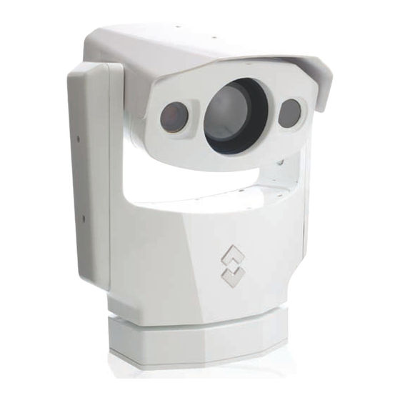
The Voyager III includes a camera body to install on the deck house or mast location of your choice, a bulkhead box for installation below deck, and one or more joystick control units (JCU) for installation at the primary pilot station and any other location where you want to be able to operate the camera. - Page 10 Internet connection, letting you view what is happening near your vessel even when you are miles away. The Voyager III easily integrates with other navigation equipment such as radar or GPS and communicates through the standard National Marine Electronics Association (NMEA) 0183 protocol.
-
Page 11: System Components
• Connector cables • Joystick control unit (JCU) and weather cover This manual describes how the Voyager III system operates. It assumes that your system is installed and ready to use. For details about installing the system, see the Voyager III Installation Guide The Voyager III Camera Body The camera body’s pan/tilt mechanism allows the operator to look 360°... -
Page 12: Voyager Iii Bulkhead Box
Voyager III Overview In its default setting, Voyager III zooms digitally from the wide field of view (FOV) camera to the narrow FOV camera. At the point when the wide FOV reaches 2X zoom, the system switches over to the narrow FOV camera and zooms digitally to its maximum magnification. -
Page 13: Joystick Control Unit (Jcu)
Voyager III Installation Guide Joystick Control Unit (JCU) The JCU is the primary control device for the Voyager III system. The JCU is used to power up the camera or put it in a standby state, to operate the pan (rotation) and tilt movement of the camera, to control the Voyager III tracking features, and to configure the camera settings by means of on-screen menus. -
Page 14: Video Display
Video Display The two thermal imagers that are part of the Voyager III system do not produce images from visible light like an ordinary camera does or like the human eye does. Rather, they use thermal infrared energy to produce images by sensing subtle differences in temperature and generating images based on those differences. -
Page 15: Video Screen Icons
User Programmable Button Menu System Setup Menu About Help Menu Point: Disabled Park Press MENU to exit Joystick Up/Down to select Joystick Left/Right to change Scene Icon Position Icon Elevation Icon PC Icon JCU Icon 432-0005-00-10 Rev 100 — Voyager III Operator’s Manual... - Page 16 Voyager III Overview 432-0005-00-10 Rev 100 — Voyager III Operator’s Manual...
-
Page 17: Chapter 2 Voyager Iii Joystick Control Unit
Control Unit JCU Introduction The JCU is the primary method of controlling the Voyager III camera. You use it to move the camera (pan or tilt), electronically zoom the camera in and out, switch between infrared and visible-light cameras, adjust the image quality, enable or disable the video tracker, and access the on-screen menus. -
Page 18: Power/Dim Button
In many cases, you will not need to modify the factory default configuration settings of your Voyager III system. However, the system gives you many options that you may want to tailor to your own needs. These settings are available through on-screen menus. -
Page 19: Scene Button
Based on personal preferences, one of the other color settings (or color palettes) can be chosen as a default. 432-0005-00-10 Rev 100 — Voyager III Operator’s Manual... -
Page 20: Home Button
HOME buttons in unison. Note: This button sequence is essentially a hard shutdown. The JCU does not go into a countdown mode or display the Power Menu. The system immediately goes into global standby mode. 432-0005-00-10 Rev 100 — Voyager III Operator’s Manual... -
Page 21: Button Summary
It can also be pushed in (like a mouse click) or pulled out. It is used to move the pan/tilt position of the camera, change the focus, and zoom in and out. 432-0005-00-10 Rev 100 — Voyager III Operator’s Manual... -
Page 22: Tilting The Camera
(click) or push it right/left to select a menu item. If you are using the Voyager III tracking feature, you use the puck to control the tracking acquisition window and other aspects of tracking. See “Joystick Operation for Tracking”... -
Page 23: Focusing The Camera
The Autofocus scale shows progress of the focus operation Use the manual focus controls for coarse focus adjustment and the autofocus feature for fine focus adjustments of the thermal image. 432-0005-00-10 Rev 100 — Voyager III Operator’s Manual... -
Page 24: Jcu Display
The Power Menu displays on the LCD so you can choose various standby modes. See “JCU Power Menu” on page 26 for details about using this menu. JCU powered on with backlit display and buttons 432-0005-00-10 Rev 100 — Voyager III Operator’s Manual... -
Page 25: Chapter 3 Voyager Iii System Startup
CHAPTER 3 System Startup and Shutdown The Voyager III camera does not have an on/off switch. Instead, its power state is controlled by the JCU. Generally, the camera is never completely off but in a standby state waiting for a “wake” command from the JCU. - Page 26 In general, the following sequence occurs: Two FLIR splash screens display. Initially the screen at the left appears. Then another splash screen with two important notices appears. Product Not for use as a...
-
Page 27: Standby Mode
If Camera, System, or Global Stndby is selected, the LCD displays Goodbye, the camera moves to the parked position (head rotated down) and goes into standby state. 432-0005-00-10 Rev 100 — Voyager III Operator’s Manual... -
Page 28: Jcu Power Menu
Power Menu displays when you enter the menu. Use the puck to scroll down through the other menu options. To exit the Power Menu, scroll down to the Cancel entry and push the puck in. 432-0005-00-10 Rev 100 — Voyager III Operator’s Manual... - Page 29 After entering calibration mode, you will be instructed to move the puck to the maximum extent possible in each direction separately. After that has been done, pushing the puck in moves to the next step. For example, Rotate CW/CCW 432-0005-00-10 Rev 100 — Voyager III Operator’s Manual...
-
Page 30: Factory Default Settings
The Cancel option causes the JCU to exit the Power Menu and return to its normal state. Factory Default Settings Table 3.1 shows the factory default settings for the Voyager III configuration options and the JCU buttons. Chapter 5, "Voyager III System Configuration," on page 43 describes how to modify and update settings. - Page 31 Thermal Color Disabled TTM Message Disabled Twist-to-Pan Mode Enabled USER button (press and hold) Display User Programmable Button Menu USER button (short press) Toggle Video Polarity Video Polarity Black Hot Webcam Disabled 432-0005-00-10 Rev 100 — Voyager III Operator’s Manual...
- Page 32 Voyager III System Startup 432-0005-00-10 Rev 100 — Voyager III Operator’s Manual...
-
Page 33: Chapter 4 Voyager Iii Firefighter Mode And Tracking
CHAPTER 4 Mode and Tracking Overview The chapter provides instructions for using two specialized features of the Voyager III system that are particularly useful in rescue operations: • Firefighter mode • Video tracking Using Firefighter Mode When the system is in firefighter mode, the estimated temperature of a target area is monitored and displayed on the screen. - Page 34 Voyager III Firefighter Mode and Tracking Caution: A number of factors can affect the accuracy of the Voyager III temperature reading such as the distance to the target, humidity, and other atmospheric conditions. While the Firefighter Mode features of your Voyager III...
-
Page 35: Using Voyager Iii Tracking
The ability to identify a target and keep the camera automatically focused on it is an important feature of your Voyager III system. Tracking can be used, for example, to keep a person in view who has been swept overboard until a rescue operation is completed or to follow a ship that is in distress. - Page 36 It has three states, indicated by the color: • White indicates that the tracker is in acquisition mode and not actively tracking a target. The area within the tracking gate identifies a potential target. 432-0005-00-10 Rev 100 — Voyager III Operator’s Manual...
- Page 37 If you plan to use tracking, some initial setup is required. Entering a tracking session significantly alters the way the Voyager III system works. Tracking affects 432-0005-00-10 Rev 100 — Voyager III Operator’s Manual...
-
Page 38: Setup For Tracking
Setup for Tracking If you plan to use the Voyager III tracking module, you must first: • Associate Toggle Tracker with the long press of the USER button. This is the only way to turn tracking on and off. -
Page 39: Tracking Concepts
Note: Again, the behavior of the system when the active tracking algorithm is SCENE is different. Rather than a green tracking gate, you will see multiple green cross hairs scattered across the entire scene. 432-0005-00-10 Rev 100 — Voyager III Operator’s Manual... -
Page 40: Tracking Algorithms
“coast,” predict where the target will be next based on its previous rate of change, and attempt to reacquire it. If the target cannot be clearly identified within the coast period, you will need to reacquire it manually. 432-0005-00-10 Rev 100 — Voyager III Operator’s Manual... -
Page 41: Joystick Operation For Tracking
• Change the vertical and horizontal position of the tracking gate (joystick). • Move the horizontal and vertical offset of the region being tracked (press and hold MENU button and use puck). 432-0005-00-10 Rev 100 — Voyager III Operator’s Manual... - Page 42 (unless you quickly reacquire, as described in the previous section). You also can hold down the MENU button and cycle through the four tracking algorithms using puck movements. 432-0005-00-10 Rev 100 — Voyager III Operator’s Manual...
- Page 43 You hold down the MENU button and use the joystick to move the tracking gate to the left. This shifts the scene so that the missing part of the boat comes into view. 432-0005-00-10 Rev 100 — Voyager III Operator’s Manual...
- Page 44 Move track offset down Left No Response Move track offset left Right No Response Move track offset right Twist Counter Clockwise Move track offset left No Response Twist Clockwise Move track offset right No Response 432-0005-00-10 Rev 100 — Voyager III Operator’s Manual...
-
Page 45: Chapter 5 Voyager Iii System Configuration
Overview This chapter describes how to configure the system options using on-screen menus. To operate the Voyager III camera does not require modifying any of the factory configuration settings. However, these menus let you: • Choose configuration options that match your personal preferences or provide optimal performance under varying conditions, such as a default color scheme. -
Page 46: Main Menu
If you are in a submenu, you may need to press the MENU button multiple times to exit. The currently active menu item is designated by the FLIR logo next to it. Push the puck in or move it left/right to select an item. Another menu displays if the item is a menu, or the value changes if it is a functional option. -
Page 47: Firefighter Menu
NMEA Web site: http://www.nmea.org/content/nmea_standards/nmea_standards.asp When NMEA is being used, the Voyager III acts as a listener and receives messages from the main control unit that is monitoring various sending devices in... - Page 48 Voyager III System Configuration the system, such as radar, GPS, or independent input ports. The Voyager III connects to the other equipment via a serial cable or a direct connection. The NMEA protocol allows the camera to automatically point toward vessels and other objects that show up on the display and to track their movement.
-
Page 49: Nmea Mode
Dwell time determines how long the camera remains on a particular target. The ability of the Voyager III to accurately track a target depends on the quality of the data sent from the radar unit. The ability of the radar to effectively track a... -
Page 50: Bwc Message
NMEA Target Tracking Messages (TTM) provided by the radar unit. While it is possible to select up to 100 targets to be tracked by Voyager III (refer to the radar or GPS documentation on how to designate a target), typically the operator selects five or less. -
Page 51: Target Dwell
Voyager III system and is not aligned with it. For example, if the Voyager III system is located to one side of a large boat some distance from a radar system, you can specify values for the mounting offset to ensure greater accuracy of tracking. -
Page 52: Set Thermal Color Default
COLOR button. See “COLOR Button” on page 17 for details. Color Thermal Video Disabled. Day and night pallets (white/black or red/ black) display as you press the JCU COLOR button. This is the factory default setting. 432-0005-00-10 Rev 100 — Voyager III Operator’s Manual... -
Page 53: Test Pattern
Test Pattern Quite often the video from the Voyager III camera can be optimized by adjusting the monitor that is being used to show the video. The Display Test Pattern function is useful for setting up the monitor to give the best detail and contrast. -
Page 54: Set Symbology Menu
The PC icon only appears if the system has discovered a PC on the network. This happens only when you have completed the setup to enable the use of the system as a webcam. See Chapter 6, "Voyager III Webcam Interface," on page Icon Display Mode The general display of icons on the screen is controlled by the setting of Icon Display Mode. -
Page 55: Elevation Icon
Note: The PC, JCU, and Elevation icons do not display in minimal mode even when their icon settings are enabled. Hide All. None of the icons display permanently, except for the FLIR logo and the Position Indicator and icons for the following special modes: •... -
Page 56: Short Press
When you select System Setup Menu from the main menu, the following on-screen menu displays. Align Thermal Images Foveal View: Disabled Gyro Stabilization: Enabled Joystick Mode: Airplane Twist-to-Pan Mode: Disabled Webcam: Enabled Surveillance Menu Analog Video Menu Tracker/PIP Menu 432-0005-00-10 Rev 100 — Voyager III Operator’s Manual... -
Page 57: Align Thermal Images
An unlock icon may also displays momentarily when you modify the gyro stabilization setting if Point is disabled. If Point is enabled, the lock icon displays and remains on the screen indicating that the camera movement is constrained (Point enabled). 432-0005-00-10 Rev 100 — Voyager III Operator’s Manual... -
Page 58: Joystick Mode
A quick push in initiates autofocus. Note: When you are using the Voyager III tracker, Twist-to-Pan Mode also affects how you use the joystick puck to manage tracking features. See Table 4.1 and Table 4.3 on page 42 for a summary. -
Page 59: Webcam
Voyager III System Configuration Webcam Use this option to enable or disable the use of the Voyager III from a PC on a local or remote connection. Setting up the integration of the system so that it can be accessed from a computer is a separate activity. Enabling the webcam feature sets up the system to allow the video to be displayed remotely. -
Page 60: Analog Video Menu
Choose one of four types of display for the primary and secondary output: • OSD Video is a blended, processed view of output from the three cameras included in the Voyager III—WFOV, NFOV, and visible—and includes on- screen icons and menus. This is the factory default setting for the primary display. -
Page 61: Tracker/Pip Menu
Tracker/PIP Menu Your Voyager III system includes a tracker that lets you choose a target area of the display and have the tracker keep the camera focused on that area. Tracking is discussed in “Using Voyager III Tracking” on page 33. -
Page 62: About Help Menu
Version Information Selecting Version Information displays the software version information for the Voyager III camera you are using. If you are having any problems with the camera, have this information available when contacting FLIR technical support. An example of the display is shown below. -
Page 63: Point And Park
Enabling Point turns off the horizontal (pan) stabilization while retaining the tilt stabilization. This can be helpful when you want to use Voyager III as an aide to navigation and keep the camera pointing in the same position relative to the vessel as it turns. - Page 64 While in Park position, the Park icon displays on the video screen. Touching the joystick or any of the buttons on the JCU returns the camera to its previous state (before going into park). 432-0005-00-10 Rev 100 — Voyager III Operator’s Manual...
-
Page 65: Chapter 6 Voyager Iii Webcam Interface
If your local area network (LAN) on your vessel is set up with access to the Internet, the Voyager III webcam feature can be extended so that you can access the camera remotely through the Internet. This setup would let you keep an eye on your vessel from anywhere in the world as long as you can find an Internet connection. -
Page 66: Basic Webcam Configuration
See “Installing the VLC Player” on page 69 for details. Configuration Steps Configuring the Voyager III webcam feature for local use involves the following steps: Configure your local PC to use an IP address in the same range as the Voyager III camera. - Page 67 Most PCs are configured to obtain an IP address automatically from the network. You need to change the network settings for the PC to correspond to the Voyager III camera. How you do this will vary depending on which operating system your PC is using.
-
Page 68: Using The Webcam Interface
The webcam control screen looks like the following figure. If you see an ActiveX warning, right click the message and choose the option to install the ActiveX control. It may take a moment for the video to start streaming. 432-0005-00-10 Rev 100 — Voyager III Operator’s Manual... -
Page 69: Controlling Camera Position
The camera symbol indicates the direction the Voyager III camera is pointing relative to the bow of the vessel. While you can use the Home button to return the camera to its home position, you cannot change the home position through the GUI. -
Page 70: Image Mode Control
Using the DLTV controls, you can select the daylight camera as your video input stream. When Video is selected, use the other settings to move the camera view in and out and to adjust the field of vision. 432-0005-00-10 Rev 100 — Voyager III Operator’s Manual... -
Page 71: Web Browser Configuration
Voyager III Webcam Interface Web Browser Configuration The Voyager III webcam feature should be used with Microsoft Internet Explorer 8 or higher. Browser Security Settings In order to be able to download the required VLC Player or run it as an ActiveX control in your browser, you may need to change some IE security settings or respond to security warnings when prompted. - Page 72 For example, you may only want to use VLC with video files so you can uncheck other file type associations. Click Next to continue. Choose a location for the installed files or accept the default. 432-0005-00-10 Rev 100 — Voyager III Operator’s Manual...
-
Page 73: Advanced Configuration Topics
Make sure you know how to manage and configure the other equipment in the network (for example, the cable, DSL or wireless modem/router used to connect to the Internet). FLIR technical support can only provide limited support in this regard. -
Page 74: Changing Voyager Iii Camera Static Ip Address
HTTP Webcam You may want to change the IP address for the Voyager III camera from the default value (192.168.250.116) to an address that is within the address space of the existing IP network on the vessel. For example, you may already have devices such as IP cameras, PCs, and routers attached to a local area network (LAN). - Page 75 When this screen appears, click the link to log in as the basic user. You can ignore the User and Password fields. The Help screen displays. Click the LAN Settings tab on the left. 432-0005-00-10 Rev 100 — Voyager III Operator’s Manual...
-
Page 76: Changing The Ip Address Of The Jcu
IP address automatically from your local network. Changing the IP Address of the JCU The JCU communicates through the ethernet IP protocol just like the Voyager III camera does. Each JCU comes with a static IP address assigned. If you plan to... -
Page 77: Enabling Universal Plug And Play (Upnp)
A UPnP compatible device from any vendor can dynamically join a network, obtain an IP address, announce its name, convey its capabilities upon request, and learn about the presence and capabilities of other devices. 432-0005-00-10 Rev 100 — Voyager III Operator’s Manual... - Page 78 Voyager III cameras and JCUs are UPnP devices so they broadcast their presence on the network. A PC configured to accept UPnP broadcasts will show all UPnP devices discovered under My Network Places.
-
Page 79: Using The Webcam Feature Remotely
Configuring this kind of network is outside the scope of this manual. The following diagram shows a typical scenario where a laptop in a remote location is being used to connect to the Voyager III camera over the Internet. It is assumed the router/gateway will perform Network Address Translation (NAT) and port forwarding. -
Page 80: Configuring The Camera To Output To A Remote Device
Voyager III Webcam Interface Warning: To protect against unauthorized access to your camera from other Internet users, you must take steps to protect your connection. FLIR recommends that you set up a firewall on your router. Configuring the Camera to Output to a Remote Device In some circumstances, you may have a need to send output from the camera to be viewed on a video display at a remote location. - Page 81 After you enter the external IP address, scroll down the page and click the Save button. Then repeat the same steps for the other two devices. Caution: Remember to click Save before selecting another device or your changes will not be saved. 432-0005-00-10 Rev 100 — Voyager III Operator’s Manual...
-
Page 82: Custom Network Applications
The SDK is available for download at no charge from the FLIR Network Systems Web site. The SDK helps software developers create SDK-based applications that make use of the rich features in the Nexus application. -
Page 83: Resources Available
Training If you are interested in learning more about thermal imaging cameras, FLIR offers complimentary training courses at the Infrared Training Center: http://www.flir.com/training... - Page 84 Voyager III Webcam Interface 432-0005-00-10 Rev 100 — Voyager III Operator’s Manual...
-
Page 85: Chapter 7 Voyager Iii Reference
Application Programming Interface NMEA Bearing and Distance to Waypoint, Great Circle CIDR Classless Inter-Domain Routing DHCP Dynamic Host Configuration Protocol Export Administration Regulations Electromagnetic Interference Flat Field Correction FLIR Forward Looking Infrared 432-0005-00-10 Rev 100 — Voyager III Operator’s Manual... - Page 86 National Marine Electronics Association On-Screen Display Pan/Tilt Power Over Ethernet NMEA Radar System Data Real-time Transport Protocol SCTE Society of Cable Telecommunications Engineers Software Developer’s Kit NMEA Target Tracking Message Volts, Direct Current Visible 432-0005-00-10 Rev 100 — Voyager III Operator’s Manual...
-
Page 87: List Of Icons
The shaded triangle shows the approximate camera field of view (FOV). Elevation (Tilt) Shows the vertical tilt of the camera. The shaded triangle shows the approximate camera position. 432-0005-00-10 Rev 100 — Voyager III Operator’s Manual... - Page 88 Indicates a PC on the network has a connection with the camera. You can use the PC to perform basic camera controls and view the video output. See Chapter 6, "Voyager III Webcam Interface," on page 63 for details on integrating with a computer.
-
Page 89: System Specifications
The Voyager III system includes the thermal imaging components listed in Table 7.2. If the components you have are different from those listed here, please contact FLIR immediately using the contact information printed on the back of this guide. 432-0005-00-10 Rev 100 — Voyager III Operator’s Manual... - Page 90 Quick Start Guide Provided on CD or printed 432-0005-00-11 Installation Guide Provided on CD or printed 432-0005-00-12 Table 7.3 lists the optional accessories you can purchase for your Voyager III system. Voyager III Accessories TABLE 7.3 Accessories Description Part Number...
-
Page 91: System Overview
BNC Terminated, 75’ 308-0164-75 BNC Terminated, 100’ 308-0164-100 Power Accessory Injector – DC/DC PoE 4113746 System Overview Table 7.4 lists general characteristics of your Voyager III system. Voyager III Overview TABLE 7.4 Attribute Value General Size 15” x 23” Weight 45 lb. -
Page 92: Troubleshooting Tips
If the camera still does not produce an image, contact the FLIR dealer or reseller who provided the camera, or contact FLIR directly (contact information is provided on the rear cover of this manual). - Page 93 Image too dark or too light By default, the Voyager III thermal camera uses an Automatic Gain Control (AGC) setting that has proven to be superior for most applications. However, a specific environment may benefit from a different AGC setting. For example, a very cold background (such as the sky) could cause the camera to use a wider temperature range than appropriate.
- Page 94 In general, the camera will respond to the last command received and there is no way to set priority, given that IP networks use a “best effort” delivery protocol. 432-0005-00-10 Rev 100 — Voyager III Operator’s Manual...
- Page 95 NOTES...
- Page 96 PH:+ 1 888 747 3547 (Apps) FX: + 1 805 685 2711 sales@flir.com EUROPE CS Eurasian Headquarters FLIR Systems CVS BV Charles Petitweg 21 4847 NW Teteringen - Breda Netherlands PH: + 31 (0) 765 79 41 94 FX: + 31 (0) 765 79 41 99 flir@flir.com...
Need help?
Do you have a question about the Voyager III and is the answer not in the manual?
Questions and answers