FLIR M400 Operator's Manual
Hide thumbs
Also See for M400:
- Operator's manual (102 pages) ,
- Installation manual (59 pages) ,
- Quick start setup (2 pages)
Table of Contents
Advertisement
Quick Links
Advertisement
Table of Contents

Related Manuals for FLIR M400


Summary of Contents for FLIR M400
- Page 1 Operator’s Manual M400...
- Page 2 © 2015 FLIR Systems, Inc. All rights reserved worldwide. No parts of this manual, in whole or in part, may be copied, photocopied, translated, or transmitted to any electronic medium or machine readable form without the prior written permission of FLIR Systems, Inc.Names and marks appearing on the products herein are either registered trademarks or trademarks of FLIR Systems, Inc.
-
Page 3: Table Of Contents
Park Mode ..................13 The Bootup Process ................13 Powering the Camera..............13 Powering the JCU II..............14 JCU II Power Menu ................15 Standby States................15 M400 Joystick Control Unit Introduction..................16 JCU II Buttons ..................16 Power Button ................16 Menu Button ................16 Scene Button—IR imaging only..........17 Color Button—IR Imaging only ..........17... - Page 4 Display Camera and JCU II IP Address........18 JCU II Joystick..................18 Tilting the Camera ................18 Rotating the Camera ..............19 Zooming the Camera..............19 Button Summary................19 M400 System Configuration Overview ....................20 Main Menu..................20 Park camera: ................21 InstAlert/Exit InstAlert mode: ..........21 IceAlert/Exit IceAlert mode: ............21 Surveillance: ................22...
- Page 5 Next Waypoint (BWC): ............29 Radar target (TTM): ..............29 IP Interface and PC Operations M400 Web Browser Interface .............30 View Camera and JCU II IP Address ...........31 Camera Web Server Login Accounts ...........31 Log in to the Camera Web Page ..........31 Setup and Configuration Menus ...........36...
- Page 6 Contents Changing the IP Address of the JCU II........50 Enabling Universal Plug and Play (UPnP) .........51 UPnP Overview ................51 Enabling the UPnP User Interface..........52 M400 Reference Information Introduction..................53 Acronyms ...................53 List of Icons ..................54 System Specifications ................57 Troubleshooting Tips ................57 Video not displayed on monitor ..........57...
-
Page 7: M400 Overview
M400 Overview General Information This manual describes the operation of the M400 cameras. If you need help or have additional questions, please call to speak with our support experts; refer to the phone numbers listed on the back cover of this manual. -
Page 8: Documentation Conventions
Caution: Be careful not to leave fingerprints on the M400 optics. Caution: The M400 requires a power supply of 12 Vdc to 24 Vdc nominal, 5.5 A maximum @ 24 Vdc, 11 A maximum @ 12 Vdc. Absolute voltage range: 12 Vdc to 32 Vdc. Operating the system outside of the specified input voltage range or the specified operating temperature range can cause permanent damage. -
Page 9: System Description
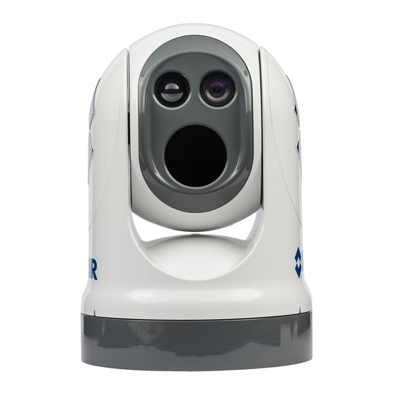
System Description System Description The multi-sensor M400 is a stabilized maritime thermal and high definition (HD) visible-light camera system for use on most types of vessels. The long wave infrared (LWIR) thermal camera provides excellent nighttime visibility and situational awareness, without any form of natural or artificial illumination. -
Page 10: M400 Components
The JCU II has various buttons, an LCD display, and the joystick. The joystick can be moved left and right or forward and back, and rotated in either direction. “M400 Joystick Control Unit” on page 16 describes the functions of the JCU II in detail. -
Page 11: Thermal Video Display
FLIR Systems, Inc. offers a comprehensive selection of training courses to help you to get the best performance and value from your thermal camera. Find out more at the FLIR training Web page: http://www.flir.com/training... -
Page 12: Position Indicator Icons
Thermal Video Display Position indicator icons The azimuth position indicator shows the direction the camera is pointing relative to the vessel. The shaded triangle shows the approximate camera field of view (FOV). The elevation position indicator shows the vertical tilt of the Azimuth Elevation camera above or below the horizontal plane of the vessel. -
Page 13: M400 System Startup
M400 System Startup System Startup and Shutdown The M400 camera does not have an on/off switch. Instead, its power state is controlled by the JCU II. Generally, the camera is never completely off but in a Park mode or standby state waiting for a “wake”... -
Page 14: Powering The Jcu Ii
Select camera camera ID, such as M400. When more than one camera is found on the network, the JCU II attempts to reconnect to the last camera it was connected to, or if it has not connected to a camera, it will prompt the user to select a camera. -
Page 15: Jcu Ii Power Menu
JCU II Power Menu JCU II Power Menu The JCU II LCD screen generally shows the ID of the camera that is connected to the JCU II. The various functions are accessed from a set of menus, with each menu entry selectable in the JCU II display. -
Page 16: M400 Joystick Control Unit
Introduction The Joystick Control Unit (JCU II) is the primary method of controlling the M400 camera. Use it to move the camera, zoom the camera, switch between infrared and visible-light cameras, adjust the image settings, and access the on-screen menus. -
Page 17: Scene Button-Ir Imaging Only
• Menu – Exit Menu Back Select Scene Button—IR imaging only The M400 thermal sensor automatically adjusts to changing conditions providing optimized high-contrast images. The preset automatic gain control (AGC) settings offer the most balance and image quality for specific conditions. Experiment with the different settings to find out which settings work best in different conditions. -
Page 18: Focus Buttons
JCU II Joystick Focus Buttons The M400 thermal camera can be focused either manually or automatically. The visible-light camera is always focused automatically. The manual focus buttons are effective only when the IR camera is the Active Camera. the – button will move the focus nearer... -
Page 19: Rotating The Camera
Use the joystick to rotate the camera to the left and right. Push the joystick to the right and the M400 will pivot to the right. Push the joystick to the left and the M400 will pivot left. Zooming the Camera Twisting the joystick causes the camera to zoom in (clockwise) or zoom out (counterclockwise). -
Page 20: M400 System Configuration
Overview This chapter describes how to configure the system options using on-screen-display (OSD) menus. Operating the M400 camera does not require modifying any of the factory configuration settings. However, the OSD menus allow setting the following: • Choose configuration options that match personal preferences such as Joystick Mode or the default color scheme. -
Page 21: Park Camera
Stand-by) except that the video is turned off. To exit Park position and return to normal operation, press the Home button. The camera will then return to Home position. The Park position can be reconfigured by an admin user through the web browser interface. See “M400 Web Browser Interface” on page 30. -
Page 22: Surveillance
Main Menu Surveillance: When the camera is in surveillance mode, it pans continuously left and right, until it is taken out of surveillance mode or until the JCU II is used to move the camera. The camera does not automatically resume panning; enable surveillance again by pressing a User button (if it is programmed to enable this mode) or selecting it in the main menu. -
Page 23: Spotlight
Image Settings Menu The following main menu buttons provide additional choices for system settings and information. End of menu symbol Menu will loop to the other end Spotlight: Select this option and then select one of the active spotlight modes (On, Flash, SOS). -
Page 24: Stabilization
Selecting Minimal turns off most of the on-screen icons except when their corresponding controls are actively in use. The pan position (azimuth) icon, tilt (elevation) position icon, and the FLIR logo are always displayed. Other icons such as home and scene display on the screen only momentarily when they are changed. -
Page 25: Icon & Text Color
Set-up Menu Icon & text color: Red/White VIS low light mode: On/Off Set-up Menu When Setup is selected from the main menu, the following OSD menu is shown. Save current settings as start-up defaults: Select this option to store the current camera settings described below for start-up or anytime Restore settings from defaults is selected. -
Page 26: Calibration & Diagnostics
Set Az & El zero reference: Icons on the video show the direction the camera is facing in relation to an outline of a ship. The M400 camera has a “forward” direction adjustment which has been set at the factory. After the camera is installed, both the azimuth and elevation should be set to account for variations required during installation so that the icons on the video show the expected angular position of the camera. -
Page 27: User Interface Preferences Menu
Additional information regarding the protocol can be found on the NMEA Web site: http://www.nmea.org/content/nmea_standards/nmea_standards.asp. When NMEA is being used, the M400 acts as a listener and receives messages from the main control unit that is monitoring various sending devices in the system, such as radar, GPS, or independent input ports. - Page 28 Additional settings such as target dwell time affect how the messages are processed. Dwell time determines how long the camera remains on a particular target. The ability of the M400 to accurately track a target depends on the quality of the data sent from the radar unit.
-
Page 29: Nmea Settings
Icon Display Mode. While it is possible to select up to 100 targets to be tracked by M400 (refer to the radar or GPS documentation on how to designate a target), typically the operator selects five or less. Once targets are selected, the camera will point toward each sequentially, and track it using position data sent from the radar unit. -
Page 30: Ip Interface And Pc Operations
Web browser when a PC or a laptop is connected to the network. The M400 camera and JCU II are shipped with Dynamic Host Configuration Protocol (DHCP) enabled to assign IP addresses. -
Page 31: View Camera And Jcu Ii Ip Address
M400 Web Browser Interface View Camera and JCU II IP Address Connect the camera and JCU II together through the switch and power on both the camera and the switch. (The JCU II is a PoE device getting power from the switch.) On the JCU II, press and hold the COLOR button while pushing the joystick forward. - Page 32 The Live Video page will be displayed, with a live image from the camera on the left part of the page and a virtual joystick and function buttons on the right part of the page. Next to the FLIR logo along the top of the screen are some menu choices, including Live Video (the red text indicates it is selected), Setup, Maintenance, Help, and Log out.
- Page 33 If it is necessary to contact FLIR Technical Support for assistance, it will be helpful to have the information from this page (such as Software Version) on hand.
- Page 34 M400 Web Browser Interface The functions of the buttons appearing for the M400 cameras are described below: Zoom In/Zoom Out These buttons zoom the active camera (IR or daylight). Plus zooms the camera in; minus zooms the camera out. Toggle Video Source This button changes the source of the Live Video image between the IR camera and the daylight camera.
- Page 35 M400 Web Browser Interface Home Click moves the camera to the Home position; Click and Hold sets the current pan and tilt position of the camera as the Home position. Function Keys When selected, the keypad changes to an OSD control panel. Select the back arrow to return to the main keypad.
-
Page 36: Setup And Configuration Menus
Additional configuration options are available that are not described in this manual. For more information on setting or changing these camera parameters refer to the Nexus IP Camera Configuration Guide (FLIR Doc #427-0030-00-28) or contact the local FLIR representative or FLIR Technical Support. -
Page 37: Setup->Ir->Agc Scene Presets
M400 Web Browser Interface Setup->IR->AGC Scene Presets The AGC parameters affect how the overall video image appears. The default Auto algorithm is suitable for most installations, but in some cases one of the other selections may provide a more appealing image, depending on personal preferences. Be aware the settings that are optimal at one time may be less optimal a short time later, since conditions such as weather and time of day affect the image and are constantly changing. -
Page 38: Setup->Surveillance->Scan List
M400 Web Browser Interface Setup->Surveillance->Scan List To setup Presets: position camera, select Preset ID Click Set, then Save Setup->Surveillance->Auto Scan To start Auto Scan: select width and speed, then select Start Set Autoscan at Startup: select speed, select limits, click Save The Relative Auto Scan (Surveillance mode) can be started and the settings changed from the OSD menu, JCU II (UPB), or the web page. -
Page 39: Setup->Osd
M400 Web Browser Interface Setup->OSD Make selections on the OSD Web page to set the content of each level of Display Icons. Scroll down and select to enable or hide each icon for the Full, Minimal, and Custom icon sets. -
Page 40: Maintenance Menus
M400 Web Browser Interface Maintenance Menus After making configuration changes, click the Save button at the bottom of the page. After saving, it is also necessary to stop and restart the server. The server has a configuration that is active and running, and another configuration that is saved. -
Page 41: Maintenance->Server->Server Status
The admin and expert log in accounts can change LAN settings. Maintenance->Server->LAN Settings The M400 system is shipped with DHCP IP address mode enabled. Some networks may require that a static IP address is set. The camera IP address, mask, and gateway is shown in the figure below. -
Page 42: Maintenance->Server->Security Functions
M400 Web Browser Interface Maintenance->Server->Security Functions Use the Security Options page to restrict access through the camera web server to specific IP addresses and to set and change passwords. • To limit which computers have access to the web browser interface simply enter a computer’s IP address and click Add. - Page 43 M400 Web Browser Interface • The expert log in, shown below, can use the Live Video page, the Setup page, the Maintenance page Server menus, and can reset the user password or select to allow the user log in account to change their own password, as well as restrict access to specific IP addresses.
-
Page 44: Maintenance->Sensor->Devices->Pan & Tilt
M400 Web Browser Interface Maintenance->Sensor->Devices->Pan & Tilt Startup Mode Select an action the camera will perform at startup (power cycle or server reset). Scroll down to Save Select an action from the menu Azimuth and Elevation Offsets After the camera is installed, both the azimuth and elevation may be set to account for variations required during installation so that the icons on the video show the expected angular position of the camera. - Page 45 M400 Web Browser Interface Setting Park Position The default park position is defined as 0° azimuth and -90° elevation. If a non-zero Elevation Offset is set or a different park position is desired, adjust the Park position as follows: 1. Using the JCU II, drive the camera to the desired park position.
-
Page 46: Changing Video Outputs
M400 Web Browser Interface Changing Video Outputs The M400 camera system has two cameras with different video streams which are then processed to provide multiple display formats and video resolutions. Use the following web pages to control these video streams and how they are affected by Active Camera selections from the JCU II. -
Page 47: Maintenance->Sensor->Modules->Video
M400 Web Browser Interface Maintenance->Sensor->Modules->Video VIDEO 0 is the daylight camera (DLTV) video stream, VIDEO 2, shown above and at the right, is the infrared camera video stream, and VIDEO 4 is the video stream shown on the Live Video web page. -
Page 48: Maintenance->Sensor->Modules->Radar Interface
M400 Web Browser Interface Maintenance->Sensor->Modules->Radar Interface 432-0012-00-10 Version 100 December 2015... -
Page 49: Geo-Referencing Of The Sensors
M400 Web Browser Interface Geo-Referencing of the Sensors The Camera Server and the Radar Server can each have a Georeference location. When the camera is installed on a vessel, the location information can come from a GPS and gyrocompass and the information is available as NMEA data directly from those devices or through the radar device. -
Page 50: Firmware Update
Accessing the JCU II Web Interface The JCU II communicates through the Ethernet IP protocol just like the M400 camera does. Changing the IP Address of the JCU II On the JCU II, the IP address is displayed by pressing the COLOR button and pushing the joystick forward at the same time. -
Page 51: Enabling Universal Plug And Play (Upnp)
M400 cameras and JCU IIs are UPnP devices so they broadcast their presence on the network. A PC configured to accept UPnP broadcasts will show all UPnP devices discovered under My Network Places. -
Page 52: Enabling The Upnp User Interface
Enabling Universal Plug and Play (UPnP) Enabling the UPnP User Interface In some cases, Windows will discover UPnP devices and provide its own user interface to control them. Windows Vista and Windows 7 automatically detect network devices in the Network page. If UPnP devices are hidden, a prompt at the top of the screen will ask to display hidden devices. -
Page 53: M400 Reference Information
M400 Reference Information Introduction This chapter includes a glossary of acronyms, a list of symbols used in on-screen-display (OSD), and a number of lists and tables that summarize system information and show how features vary by camera model. It also includes a set of tips for troubleshooting issues. -
Page 54: List Of Icons
List of Icons Acronyms TABLE 6.1 Acronym/Term Definition NTSC National Television System Committee on-screen-display Pan/Tilt Phase Alternating Line Power over Ethernet SCTE Society of Cable Telecommunications Engineers Software Developer’s Kit UPnP Universal Plug and Play Volts, Direct Current Visible (visible-band camera reference) List of Icons Table 6.2 lists the icons that may be shown on the screen during various operations, with a brief description of their meaning. - Page 55 List of Icons Video Display Icons (Continued) TABLE 6.2 Icon Name Description Elevation (Tilt) Shows the vertical tilt of the camera. The shaded triangle shows the approximate camera position. Focus Scale Shown when autofocus is invoked to indicate the progress of the operation.
- Page 56 List of Icons Video Display Icons (Continued) TABLE 6.2 Icon Name Description NMEA TTM Receiving NMEA messages using the NMEA Tracked Target Message Message (TTM) sentence format has been enabled; this is also known as radar tracking The camera is shutting down. Power down Scene: Night One of four scene presets (automatic gain control settings)
-
Page 57: System Specifications
Troubleshooting Tips This section includes information that may help with common issues that may arise during operation of the M400 system. Video not displayed on monitor The camera will not display video if it is in standby mode. Power cycle the camera and allow the system to complete the bootup cycle prior to JCU II connection. -
Page 58: Cleaning
If the camera still does not produce an image, contact the FLIR dealer or reseller who provided the camera, or contact FLIR directly (contact information is provided on the rear cover of this manual). -
Page 59: Image Too Dark Or Too Light
Troubleshooting Tips Image too dark or too light By default, the M400 thermal camera uses an automatic gain control (AGC) setting that has proven to be superior for most applications. However, a specific environment may benefit from a different AGC setting. For example, a very cold background (such as the sky) could cause the camera to use a wider temperature range than appropriate. - Page 60 FLIR Systems, Inc. CS World Headquarters FLIR Systems, Inc. 6769 Hollister Ave. Goleta, CA 93117 PH: +1 888 747 3547, Option 5 maritimecamerasupport@flir.com 432-0012-00-10 Rev. 100 December 2015...
Need help?
Do you have a question about the M400 and is the answer not in the manual?
Questions and answers