QNAP VioStor User Manual
Hide thumbs
Also See for VioStor:
- User manual (244 pages) ,
- User manual (352 pages) ,
- User manual (235 pages)

Related Manuals for QNAP VioStor


Summary of Contents for QNAP VioStor
- Page 1 ETWORK IDEO ECORDER QNAP V ECORDING YSTEM User Manual (Version: 5.1.0) © 2015. QNAP Systems, Inc. All Rights Reserved.
- Page 2 Further, the ® or ™ symbols are not used in the text. LIMITED WARRANTY In no event shall the liability of QNAP Systems, Inc. (QNAP) exceed the price paid for the product from direct, indirect, special, incidental, or consequential software, or its documentation.
- Page 3 Important Notice Reading instructions Read the safety warnings and user manual carefully before using this product. Power supply This product can only be used with the power supply provided by the manufacturer. Service Please contact qualified technicians for any technical enquires. Do not repair this product by yourself to avoid any voltage danger and other risks caused by opening this product cover.
- Page 4 Regulatory Notice FCC STATEMENT This equipment has been tested and found to comply with the limits for a Class B digital device, pursuant to Part 15 of FCC Rules. These limits are designed to provide reasonable protection against harmful interference in a residential installation.
-
Page 5: Table Of Contents
Table of Contents Table of Contents ......................5 Safety Warning ......................11 Chapter 1. Introduction ..................12 Overview ....................12 Hardware Illustration ................13 1.2.1 VS – 12164 / 12156 / 12148 / 12140U-RP Pro+ ......13 1.2.2 VS – 12164 / 12156 / 12148 / 12140U-RP Pro ........ 14 1.2.3 VS –... - Page 6 6.1.4 Export Video Files with Digital Watermark ........133 6.1.5 Enable Recording Video Files ............134 6.1.6 Average Time-Divided Playback ............135 Play Video Files in the QNAP QVR Client for Windows ......136 Watermark Proof..................137 Access the Recording Data ..............139 6.4.1 Microsoft Networking (SMB/CIFS) ..........
- Page 7 Chapter 7. Surveillance Settings ................141 Camera Settings ..................141 7.1.1 Camera Overview ................141 7.1.2 Camera Configuration ..............141 User Defined Multi-stream ....................... 151 Smart Recording ..........................154 Edge Recording ..........................158 7.1.3 Flexible Channel Mode ..............162 7.1.4 Event Management ................ 164 Traditional Mode ..........................
- Page 8 9.1.2 Storage Manager ................233 Volume Management ........................233 RAID 0 ............................. 234 2-drive models or above........................234 RAID Management ........................... 237 Hard Disk S.M.A.R.T ........................253 9.1.3 Network ..................254 TCP/IP .............................. 254 DDNS Service ..........................262 9.1.4 Security ..................263 Security Level ...........................
- Page 9 11.3.1 How to use QSCM Lite on NVR client PC ........343 11.3.2 Usability Reminder and Suggestions ..........347 11.3.3 QSCM Lite Client Specification ............. 347 11.4 Comparison between VioStor CMS & QSCM Lite ........347 Qstart ......................349 12.1 Introduction ................... 349 12.2...
- Page 10 12.4 Qstart Mode ................... 352 12.5 Network Switch Control (Embedded) ............ 355 12.5.1 Topology: ..................355 12.5.2 Switch Control Chart: ..............356 12.5.3 Event Notifications: ..............357 12.5.4 Compatibility List: ................ 358 LCD Panel ....................359 Troubleshooting ..................365 Appendix A Configuration Examples ..............
-
Page 11: Safety Warning
Safety Warning This product can operate normally in the temperature of 0ºC–40ºC and relative humidity of 0%–90%. Please make sure the environment is well-ventilated. The power cord and devices connected to this product must provide correct supply voltage. Do not place this product in direct sunlight or near chemicals. Make sure the temperature and humidity of the environment are in optimized level. -
Page 12: Chapter 1. Introduction
Introduction 1.1 Overview The QNAP VioStor NVR (hereafter referred to as the NVR or the VioStor) is the high performance network surveillance solution for network-based monitoring of IP cameras, video recording, playback, and remote data access. Up to 128 channels from multiple QNAP NVR servers can be monitored simultaneously. -
Page 13: Hardware Illustration
1.2 Hardware Illustration 1.2.1 VS – 12164 / 12156 / 12148 / 12140U-RP Pro+ Power Button LED Indicators: 10 GbE, Status, LAN, eSATA (Reserved) eSATA x 2 (Reserved) Gigabit LAN x 4 USB 2.0 x 4 USB 3.0 x 2 Expansion Slot x 2 (Reserved) Password &... -
Page 14: Vs - 12164 / 12156 / 12148 / 12140U-Rp Pro
1.2.2 VS – 12164 / 12156 / 12148 / 12140U-RP Pro Power button LED indicators: 10 GbE, Status, LAN, eSATA Select button(Reserved) Expansion slot x 1 (reserved) Gigabit LAN x 4 USB 3.0 x 2 USB 2.0 x 4 Password & network settings reset button eSATA x 2 (reserved) 10. -
Page 15: Vs - 8148 / 8140 / 8132 / 8124U-Rp Pro
1.2.3 VS – 8148 / 8140 / 8132 / 8124U-RP Pro+ Enter Button Power Button Select Button LED Indicators: 10 GbE, Status, LAN, eSATA (Reserved) eSATA x 2 (Reserved) USB 2.0 x 4 Gigabit LAN x 4 USB 3.0 x 2 10. -
Page 16: Vs - 8148 / 8140 / 8132 / 8124U-Rp Pro
1.2.4 VS – 8148 / 8140 / 8132 / 8124U-RP Pro Enter button Power button Select button LED indicators: 10 GbE, Status, LAN, eSATA(Reserved) Expansion slot x 2 (reserved) Gigabit LAN x 2 USB 3.0 x 2 USB 2.0 x 4 10. -
Page 17: Vs - 8148 / 8140 / 8132 / 8124 Pro
1.2.5 VS – 8148 / 8140 / 8132 / 8124 Pro+ USB 3.0 One-touch -video-backup button Power button Hard drive LEDs Select button Enter button LED indicators: Status, LAN, USB, eSATA (Reserved), 10 GbE Tray lock Release button 10. Power connector 11. -
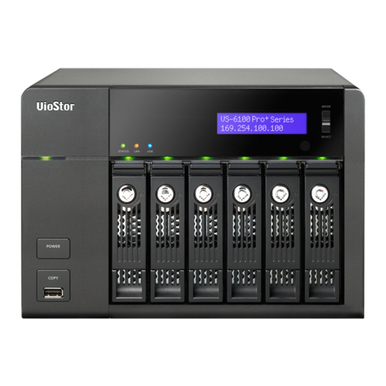
Page 18: Vs - 6120 / 6116 / 6112 Pro
1.2.6 VS – 6120 / 6116 / 6112 Pro+ One-touch -video-backup button USB 2.0 LED indicators: Status, LAN, USB, Power, HDD1-6 Power button Select button Enter button Power connector K-Lock Security Slot Gigabit LAN x 2 10. Audio In/Out 11. Password & Network Settings Reset Button 12. -
Page 19: Vs - 6020 / 6016 / 6012 Pro
1.2.7 VS – 6020 / 6016 / 6012 Pro One-touch -video-backup button USB 2.0 LED indicators: Status, LAN, USB, eSATA(Reserved), HDD1–6 Power button Select button Enter button Power connector Gigabit LAN x 2 USB 2.0 x 4 10. eSATA x 2 (reserved) 11. -
Page 20: Vs - 4116 / 4112 / 4108U-Rp Pro
1.2.8 VS – 4116 / 4112 / 4108U-RP Pro+ USB 2.0 One-touch -video-backup button LED indicators: USB, Status, HDD1–4, LAN Power button Power connector HDMI Gigabit LAN x 2 USB 3.0 x 2 USB 2.0 x 2 10. DI/DO 11. RS-485 (reserved) 12. -
Page 21: Vs - 4016 / 4012 / 4008U-Rp Pro
1.2.9 VS – 4016 / 4012 / 4008U-RP Pro One-touch -video-backup button USB 2.0 LED indicators: Status, LAN, USB, eSATA(Reserved), HDD1–4 Power button Power connector Gigabit LAN x 2 USB 2.0 x 4 eSATA x 2 (reserved) 10. Password & network settings reset button... -
Page 22: Vs - 4116 / 4112 / 4108 Pro
1.2.10 VS – 4116 / 4112 / 4108 Pro+ One-touch -video-backup button USB 2.0 LED indicators: Status, LAN, USB, HDD1–4 Power button Select button Enter button Power connector K-Lock Security Slot Gigabit LAN x 2 10. Audio In/Out 11. Password & network settings reset button 12. -
Page 23: Vs - 4016 / 4012 / 4008 Pro
1.2.11 VS – 4016 / 4012 / 4008 Pro One-touch- video-backup button USB 2.0 LED indicators: Status, LAN, USB, eSATA(Reserved), HDD1–4 Power button Select button Enter button Power connector Gigabit LAN x 2 USB 2.0 x 4 10. eSATA x 2 (reserved) 11. -
Page 24: Vs - 2212 / 2208 / 2204 Pro
1.2.12 VS – 2212 / 2208 / 2204 Pro+ One-touch-video-backup button USB 3.0 LED Indicators: LAN, HDD1, HDD2 Power Button Power Connector Gigabit LAN x 2 USB 3.0 x 2 Password & Network Settings Reset Button K-Lock Security Slot 10. Mic Input/ audio output 11. -
Page 25: Vs - 2112 / 2108 / 2104 Pro
1.2.13 VS – 2112 / 2108 / 2104 Pro+ One-touch-video-backup button USB 3.0 LED Indicators: LAN, HDD1, HDD2 Power Button Power Connector Gigabit LAN x 2 USB 2.0 x 4 Password & Network Settings Reset Button K-Lock Security Slot 10. Audio In/Out 11. -
Page 26: Vs - 2012 / 2008 / 2004 Pro
1.2.14 VS – 2012 / 2008 / 2004 Pro One-touch -video-backup button USB 2.0 LED indicators: HDD1, HDD2, LAN, eSATA (Reserved) Power button Power connector Gigabit LAN x 2 USB 2.0 x 2 eSATA x 2 (reserved) 10. Password & network settings reset button 11. -
Page 27: Vs - S2212 / S2208 / S2204 Pro
1.2.15 VS – S2212 / S2208 / S2204 Pro + LED indicators: Status, LAN, HDD1, HDD2, USB (Backup) Power button One-touch -video-backup button USB 3.0 x 2 Password & network settings reset button Mic Input/ audio output USB 3.0 Gigabit LAN x 2 HDMI 10. -
Page 28: Vs - 2108 / 2104 L
1.2.16 VS – 2108 / 2104 L One-touch-auto-video-backup button USB 2.0 LED Indicators: USB, status, HDD1, HDD2, LAN, power Power button Power connector Gigabit LAN USB 3.0 x 2 Password & network settings reset button K-Lock security slot 10. Power cord hook... -
Page 29: Chapter 2. Install The Nvr
For the information of hardware installation, see the ‘Quick Installation Guide’ (QIG) in the product package. The QIG can also be found in the product CD-ROM or QNAP website (http://www.qnapsecurity.com). 2.1 Personal Computer Requirements For better system performance, the computer should at least fulfill the following requirements: No. - Page 30 2.6GHz or above 32-bit), Mozilla Firefox 33.0 H.264/MPEG-4/ Core i7 CPU 2.8GHz CD-ROM drive or MxPEG or above Internet Download M-JPEG Quad core CPU Recommended 2.33GHz or above resolution: 1280 x More than 48 H.264/MPEG-4/ Core i7 CPU 3.4GHz 720 pixels or above MxPEG or above...
- Page 31 Security Settings of the Web Browser Please make sure the security level of the IE browser in Internet Options is set to Medium or lower. Add your NVR’s IP address to the list of Trusted sites. =>...
-
Page 32: Browse Cd-Rom
QIG: View the hardware installation instructions of the NVR. QVR: The setup program for the QNAP QVR Client, an application to see the live view and play videos recorded by the NVR. If you were unable to install the QNAP QVR Client when connecting to the monitoring/playback page of the NVR, install the plug-in from the CD-ROM. -
Page 33: Hard Disk Drives Compatibility List
This product works with 2.5-inch and 3.5-inch SATA hard disk drives from popular hard disk brands. For the hard disk compatibility list, please visit http://www.qnapsecurity.com/n/en/product_x_grade/. QNAP disclaims any responsibility for product damage/malfunction or data loss/recovery due to misuse or improper installation of hard disks in any occasions for any reasons. -
Page 34: Check System Status
2.5 Check System Status LED Display & System Status Overview Color LED Status Description A hard drive on the NVR is being formatted The NVR is being initialized Flashes green The system firmware is being updated and red RAID rebuilding is in process alternately Online RAID Capacity Expansion is in every 0.5 sec... - Page 35 Green The NVR is ready Orange The NVR is connected to the network Orange The NVR is being accessed from the Flashes orange network 10 GbE* Green (Reserved) The hard drive data is being accessed and Flashes red a read/write error occurs during the process HDD (Hard Red/...
- Page 36 Buzzer (can be disabled in ‘System Settings’ > ‘Hardware’ >’Buzzer’) Beep sound No. of Times Description Short beep (0.5 sec) The NVR is starting up The NVR is being shut down (software shutdown) The reset button is pressed The system firmware has been updated Short beep (0.5 sec) The NVR data cannot be copied to the external device by pressing the...
-
Page 37: System Configuration
2.6 System Configuration Install Qfinder Run the product CD, the following menu is shown. Click ‘Install Qfinder’. You can also download it from: http://www.qnapsecurity.com/n/en/product/app_page.php Follow the instructions to install the Finder. Upon successful installation, run the Finder. If the Finder is blocked by the firewall, unblock it. The Finder detects the NVR servers on the local network. - Page 38 Click ‘Apply’ to execute the quick setup. Add IP Cameras Please follow the steps below to add IP cameras. Go to Surveillance Settings Please login to the NVR as an administrator and click the Surveillance Settings shortcut on the QVR desktop. Go to [Camera Configuration] ->...
- Page 39 Live View Click the Monitor shortcut on the QVR desktop to go to monitoring page. If it is your first time connecting to the NVR monitoring page, you will need to install the add-on. The live video from the IP cameras configured on the NVR and the recording status of each channel are shown.
-
Page 40: Chapter 3. Use The Nvr By Local Display
Chapter 3. Use the NVR by Local Display Note: This feature is supported by the VioStor Pro(+) Series NVR only. The models include VS-12164U-RP Pro(+), VS-12156U-RP Pro(+), VS-12148U-RP Pro(+), VS-12140U-RP Pro(+), VS-8148U-RP Pro(+), VS-8140U-RP Pro(+), VS-8132U-RP Pro(+), VS-8124U-RP Pro(+), VS-8148 Pro+, VS-8140 Pro+, VS-8132 Pro+, VS-8124... - Page 41 When the NVR is turned on, the login screen will be shown. Select the language. Enter the administrator name and password. If the NVR has not been configured, skip the login page and enter Quick Configuration (refer to Chapter 3.1). Default user name: admin Default password: admin...
- Page 42 Click to select the display language. If a USB keyboard is connected, click to choose the keyboard layout. Click the keyboard icon enter the necessary information if a USB keyboard is not available. The monitoring page will be shown upon successful login, refer to Chapter 3.3 for details.
-
Page 43: Quick Configuration (Manual Setup Or Quick Setup)
3.1 Quick Configuration (Manual Setup or Quick Setup) If the NVR has not been configured, Quick Configuration Wizard will be shown. Follow the instructions of the wizard to complete the system setup. Note: All the changes will be effective only after applying the settings in the last step. - Page 44 3. You can now check that all of the NVR and Camera settings fit your needs. 4. To start the setup process, click “Proceed”.
-
Page 45: Manual Setup
3.1.2 Manual Setup Follow these procedures to setup the NVR. 1) Enter the NVR name and administrator password. 2) Set the time zone, date and time. 3) Configure the network settings. - Page 46 4) Select the disk configuration. 5) In the Summary, you can confirm your settings and click “Apply” to finish.
-
Page 48: Surveillance Settings
3.2 Surveillance Settings To manage the surveillance settings such as administrator password, network and time settings, click on the monitoring screen. Note that this button (option) will be shown for administrator access only. Select the language and click the icons to configure the settings. - Page 50 圖示 說明 Main Menu Back to Monitor Control Panel Surveillance Settings File Station Recording Backup and Storage Expansion Background Tasks External Devices Notification Options Search Help Desktop Preferences...
-
Page 51: Monitoring
3.3 Monitoring Upon successful login, the monitoring screen will be shown. Monitor the IP cameras, change the display mode, enable or disable manual recording, control the PTZ cameras, and so on. Select monitoring mode View video Camera image and IP list camera info PTZ camera control panel... - Page 52 Options: Configure the event notification settings, video window display settings, screen resolution, etc. CPU Status: Display system CPU usage Hard drives Status: Display hard drive usage About: View the server name, NVR model, and firmware version. Logout: Logout the NVR. Manual recording: Enable or disable recording on the IP camera.
- Page 53 Event Notification Icon Description Event notification: When the alarm recording is enabled and an event is detected, this icon will be shown. Click this icon to view the alert details. The alert sound can be turned on or off. To clear all the logs, click ‘Clear All’.
- Page 54 PTZ Control Panel The term ‘PTZ’ stands for ‘Pan/Tilt/Zoom’. If the IP camera supports PTZ, use the control panel on the NVR to adjust the viewing angle of the IP camera. These functions are available depending on the camera models. Please consult the camera's documentation for details.
- Page 55 Display Mode The NVR supports various display modes for monitoring. Click the correct icon to switch the display mode. Icon Description Full screen Single-channel mode 2-channel mode (click the downwards arrow to choose another 2-channel mode) 3-channel mode (click the downwards arrow to choose another 3-channel mode) 4-channel mode 6-channel mode...
- Page 56 Live View Screen Upon successful configuration of the IP cameras, enter the monitoring screen to view the live video from the cameras. If the camera supports pan and tilt functions, click the channel on the screen and adjust the viewing angle with a mouse. If zooming is supported, scroll the mouse wheel to zoom in or zoom out the video.
- Page 57 Camera Status The camera status is indicated by the icons shown below: Icon Camera Status Scheduled or continuous recording is in process This IP camera supports audio function This IP camera supports PTZ function Manual recording is enabled The recording triggered by advanced event management (‘Camera Settings’ >...
- Page 58 Connection Message If the NVR fails to display the video from an IP camera, a message will be shown in the channel window to indicate the status. Message Description If the IP camera is located on remote network or the Internet, it may Connecting take some time to establish a connection to the camera.
- Page 59 and enable the function. After that, you can select the Mount type, including wall, ceiling, and floor and then select Dewarping mode, including Perimeter mode, Quad mode, and PTZ mode. Remark 1: To see a list of camera models that support panomorph lenses, please visit http://www.qnapsecurity.com/n/en/qa/con_show.php?op=showone&cid= 128.
- Page 60 Options To configure advanced monitor settings, click The following options are listed under the ‘General’ tab. Event Notification: When ‘Enable alert for all surveillance events’ option is enabled and a surveillance event is triggered, the alert icon will be instantly shown on the monitoring page.
- Page 61 The following options are provided under the ‘Video’ tab. Highlight the video window when an event is triggered: The video window will flash if an event is triggered. Display unauthorized channels: Select this option to show channels that the user does not have the access rights to.
- Page 62 If the monitor model cannot be detected, the NVR will provide resolution options of 1920x1080, 1400x1050, 1280x1024, and 1024x768.
-
Page 63: Video Playback
3.4 Video Playback The videos on the NVR can be played using the local display. To use this feature, click on the monitoring screen. Most of the icons on the playback screen are the same as those on the monitoring screen. Please refer to Chapter 3.2 for the icon description. - Page 64 Playback Settings: Play, pause, stop, reverse play a video file, or select to play the previous or next file. When playing a video, use the scroll bar to adjust the playback speed or click on the digital zoom icon to zoom in/out the video. Right click on the IP camera channel to select the following options: Full screen Keep aspect ratio...
- Page 65 mode, and PTZ mode. Remark 1: To discover what camera models can be installed with panomorph lenses, please visit http://www.qnapsecurity.com/n/en/qa/con_show.php?op=showone&cid=128. Remark 2: The function is only available when the video stream resolution is higher than 640x480 on the monitoring page. Remark 3: If Dewarping mode is in PTZ mode, for the channel, you can use the PTZ control panel or mouse (by holding down the mouse left button, and then moving the mouse or turning the mouse wheel) to change viewing angles or...
-
Page 66: Video Conversion & Export
Standard AVI file: Convert recording files to standard AVI file. More time is needed to export, but no additional codecs are required. Optimized QNAP AVI file: Convert files using an enhanced QNAP codec. Less time is needed to export, but the QNAP codec is required. - Page 67 Enter the file name of the video file. Click ‘OK’ to convert the video files to an AVI file and save them to the external USB storage device.
-
Page 68: Chapter 4. Qvr Basics And Desktop
The intuitive, multi-window and multi-tasking QVR GUI makes it incredibly easy to manage your VioStor NVR, utilize its rich surveillance applications, and install a rich set of applications in the App Center on demand to expand your VioStor NVR experience. -
Page 69: Connect To The Nvr
When accessing the NVR via Internet Explorer, you will be prompted to install the ActiveX add-on. To view the live video with Google Chrome, Mozilla Firefox or by using the QNAP QVR Client on Windows PC, please visit http://www.qnapsecurity.com/download.asp... -
Page 70: Using The Qvr Desktop
Toolbar Main Menu Click to show the Main Menu. It includes three parts: 1) QNAP applications; 2) system features and settings. Items under “APPLICATIONS” are developed by QNAP to enhance your NVR experience. Items under “SYSTEMS” are key system features designed to manage or optimize your NVR. - Page 71 show the desktop. Monitor page Click to enter monitor page Playback page Click to enter playback page Background Task Click to review and control all tasks running in the background (such as HDD SMART scanning.) External Devices Click to list all external devices that are connected to the NVR via its USB ports. Click the device listed to open the File Station for that device.
- Page 72 Notification and Alerts Click to check for recent system errors and warning notifications. Click “Clear All” to clear all entries from the list. To review all the historical event notifications, click the “Event Notifications” header to open the System Logs. For more details regarding System Logs, please refer to the chapter on System Logs.
- Page 73 Personal Setting Admin Control: Click to customize your user specific settings, change your user password, restart/shut down the NVR or log out your user account. Options (...
- Page 74 Profile: Specify your user email address. Wallpaper: Change the default wallpaper or upload your own wallpaper. Change Password: Change your login password.
- Page 75 Miscellaneous: Warn me when leaving QVR: Check this option, and users will be prompted for confirmation each time they leave the QVR Desktop (such as clicking the back icon ( ) in the browser or close the browser ( ).
- Page 76 all the current desktop settings (such as the “windows opened before your logout”) will be kept after you login the NVR the next time. Show the desktop switching button: Check this option to hide the next desktop button ( ) and last desktop button ( ) and only display them when you move your mouse cursor close to the buttons.
- Page 77 Online Resource Click to display a list of online references, including the Quick Start Guide, QVR Help, Tutorials, and QNAP Forum. Customer Service is available here. Language Click to choose your preferred language for the UI.
- Page 78 Desktop Preferences Click to choose the application icon displaying style and select your preferred application opening mode on the desktop. Application icons can be switched between small thumbnails ( ) and detailed thumbnails ) and applications can be opened in the tab mode or the...
- Page 79 window mode. For the tab mode, the window will be opened to fit the entire NVR Desktop and only one application window can be displayed at once, while in the window mode, the application window can be resized and reshaped to a desirable style. Please note: if you login the NVR using a mobile device, only the tab mode is available.
- Page 80 System Health: The status of the NVR system is indicated in this section. Click the header to open the “System Status” page. HDD Health: The status of the HDDs currently installed in the NVR will be shown in here. X1 means that only one HDD is currently installed in the NVR. For multiple HDDs installed in the NVR, the status indicated is only for the HDD with the worst condition.
- Page 81 disconnect or block a user or IP, right click the user and choose the desired actions. Click the “Online Users” header to open the corresponding page in “System Logs” for details. Scheduled Tasks: Tasks scheduled are listed here. Click the task dropdown list to list only the chosen category and the time drop down list to specify the time range for tasks to be listed.
-
Page 82: Chapter 5. Remote Monitoring
Use Google Chrome, Mozilla Firefox, or Microsoft Internet Explorer and QNAP QVR Client to monitor the IP cameras of the NVR. Note: QNAP QVR Client is a client application developed by QNAP Systems, inc., used to locally or remotely access QNAP NVR servers for performing video monitoring and playback functions. -
Page 83: Monitoring Page
5.1 Monitoring Page Upon successfully logging in, click on the QVR desktop to go to the monitoring page. Select the display language. Start to configure the system settings and use the monitoring and recording functions of the server. The following table consists of the icons and their descriptions in the monitoring page. - Page 84 Server list: Up to 128 channels from multiple QNAP NVR servers can be monitored. E-map: Upload E-map(s) and indicate the locations of the IP cameras.
- Page 85 Interactive Control Buttons Whenever you move the mouse cursor over a camera channel, the supported function buttons of the camera will show up for quick access. Icon Description Manual recording (Note 1): Enable or disable manual recording on the selected channel. The administrator can enable or disable this option on the surveillance settings page.
- Page 86 Preset position: Select the preset positions of PTZ cameras. Digital zoom (Note 5): Enable/disable digital zoom. Instant playback: On the Live-view page, whenever you want to look back to check suspicious events of a camera channel you just missed, just hit ‘Instant Playback’...
- Page 87 taken, it is caused by the network environment but not a system error. Applied to specific fisheye cameras After enabling the feature, you can select Mount type, including wall, ceiling, and floor and then select Dewarping mode, including Panorama (Full View), Panorama (Dual View), and Rectangle.
- Page 88 When the digital zoom function is enabled on multiple IP cameras, the zooming function will be affected if the computer performance is not high enough. Properties Streaming: Use custom settings Always stream from the server: Select this option to stream the audio and video data from the NVR.
- Page 89 window. Shrink image to fit window, maintaining aspect ratio Shrink image by 1/2, 1/4, 1/8… and so on to fit window Video Processing: Turn on ‘Deinterlace’ when there are interlaced lines on the video. Video Resolution: Specify to adjust the resolution automatically or use a fixed resolution.
-
Page 91: Live Video Window
5.1.1 Live Video Window The live videos of the IP cameras configured on the NVR are shown on the monitoring page. Click the channel window to use the features supported by the IP camera, e.g. digital zoom or pan/tilt/zoom. Camera Status The camera status is indicated by the icons shown below: Icon Camera Status... - Page 92 The alarm input 2 of the IP camera has been triggered The alarm input 3 of the IP camera has been triggered A moving object has been detected Digital zoom is enabled Connection Message When the NVR fails to display the video of an IP camera, a message will be shown in the channel window to indicate the status.
-
Page 93: Display Mode
5.1.2 Display Mode The NVR supports different display modes for viewing the monitoring channels. 6-channel 12-channel Sequential Single 9-channel Page 3-cha mode mode channel mode Number nnel Settings único mode único mode Multi-channe -channel 4-channel Full 8-channel 2-chann Sequential l mode mode mode Screen... - Page 94 Icon Description Digital zoom: Select a channel and click this button to enable the digital zoom function. This function can also be enabled by right clicking the display window of the PTZ camera. Press button to zoom in or button to zoom out. You can also use the mouse wheel to operate the digital zoom function.
-
Page 95: Multi-Server Monitoring
5.1.4 Multi-server Monitoring Follow the steps below to use the multi-server monitoring feature of the NVR. Click ‘Server List’ on the monitoring page. Click ‘Auto Detect’ to search for the NVR on the LAN and add the server to the server list. Click ‘Add’... -
Page 96: Monitor Settings
5.1.5 Monitor Settings To configure advanced monitor settings, click The following options are provided under the ‘General’ tab. Event Notification: When ‘Enable alert for all surveillance events’ option is enabled and a surveillance event is triggered, the alert icon will be shown on the monitoring page instantly. - Page 97 PTZ Control Panel: Select to show or hide the PTZ control panel. The following options are provided under the ‘Video’ tab. Streaming Stream from the server: If the IP camera cannot be connected from the computer, select this option and the video will be streamed from the NVR. This option does not require extra port mapping configuration;...
- Page 98 that have not been configured. The following options are provided under the ‘Snapshot’ tab. Snapshot Specify the location where the snapshots are saved and the image format (JPEG, BMP or TIFF). Show timestamp and camera name: Show the timestamp and the camera name on the snapshot.
-
Page 99: Instant Playback
5.1.6 Instant Playback On the Live-view page, whenever you want to look back to check suspicious events of a camera channel you just missed, just hit the ‘Instant Playback’ button to bring up the window to review recent feeds. While you don’t have to switch to the playback page to do so, you can still have full live views of other channels simultaneously. -
Page 100: Same-Screen Ip Camera Configurations
5.1.7 Same-screen IP Camera Configurations On the Live-view page, you can directly configure IP camera settings when needed without leaving the Live-view page, maintaining seamless s monitoring so you won’t miss any suspicious events. Please wait a moment for the system to process your request (depends on available network bandwidth). -
Page 101: Auto Cruising
5.1.8 Auto Cruising The auto cruising feature of the NVR is used to configure the PTZ cameras to cruise according to the preset positions and the staying time set for each preset position. To use the auto cruising feature, follow the steps below. On the monitoring page of the NVR, click and select ‘Connect to camera homepage’... - Page 102 Add: To add a setting for auto cruising, select the ‘Preset Name’ from the drop-down menu and enter the staying time (interval, in seconds). Click ‘Add’. Update: To change a setting on the list, highlight the selection. Select another preset position from the drop-down menu and/or change the staying time (interval).
- Page 103 Delete: To delete a setting, highlight a selection on the list and click ‘Delete’. To delete more than one setting, press and hold the Ctrl key and select the settings. Then click ‘Delete’. After configuring the auto cruising settings, select the option ‘Enable auto cruising’...
-
Page 104: Qdewarp
20 settings on the auto cruising list. 5.1.9 Qdewarp Fisheye cameras are widely used to monitor larger areas. QNAP Qdewarp allows fisheye cameras to use their full features. You only need to configure the fisheye camera’s installation location (ceiling, wall, or desk), then you can start using multiple QNAP Qdewarp modes. - Page 105 1P3R Providing 3 regional screens in the upper side, and one panorama screen in the down side 1P6R Providing 3 regional screens in the upper side and down side respectively, and one panorama screen in the center Providing 4 regional screens Providing 9 regional screens Dual Providing 2 panorama screens...
-
Page 106: Roi (Region Of Interest)
5.1.10 ROI (Region of Interest) ROI monitoring mode provides 2 monitoring layouts. You can choose a 5 or 7 split layout, and select a region of interest for monitoring. Please follow the below steps to configure the ROI. Click on the monitoring page, select , then the system will automatically go into the ROI monitoring mode. -
Page 107: E-Map
5.2 E-map The E-map feature of the NVR is provided to for users to upload electronic maps to the system to indicate the locations of the IP cameras. Users can drag and drop the camera icons* to the E-map and enable event alert to receive instant notification when an event occurs to the IP camera. -
Page 108: Icons And Description
5.2.1 Icons and Description Icon Description Enable E-map edit mode. E-map edit mode in use. Click this icon to disable the edit mode. Add an E-map. Edit the name of an E-map. Remove a map or a camera icon. Event alert not in use. Click this icon to enable event alerts on the E-map. -
Page 109: Add A Map Set Or An E-Map
5.2.2 Add a Map Set or an E-map To add a map set or an E-map to indicate the locations of the IP cameras, click to enable Edit mode. A list of IP cameras configured on the NVR will be shown on the left. Click ‘Default’ and then to add an E-map. - Page 110 To add one or multiple E-maps, e.g. office1 and office2, under an E-map, e.g. floor1, click the E-map icon of floor1 and then click to add the E-maps one by one. The icon of floor1 will be changed to when more than one E-map is added. To add another E-map of the same level of floor1, select ‘Default’...
-
Page 111: Edit A Map Name
5.2.3 Edit a Map Name To edit the name of an E-map, select the E-map and click . Enter the new name and click ‘OK’. To change the picture of the E-map, delete the E-map and add the new file. 5.2.4 Delete a Map Set or an E-map To delete an E-map, select the map and click... -
Page 112: Indicate Ip Cameras On An E-Map
5.2.5 Indicate IP Cameras on an E-map After uploading the E-maps, drag and drop the IP camera icons to the E-map(s) to indicate the camera location. The camera name will appear under the E-map on the top left column. When an icon of a fixed body or fixed dome IP camera dropped to the E-map, right click the camera icon and adjust the icon direction. - Page 113 single-channel mode on the monitoring screen. You can choose the Double-click action on the Camera Icon in “Emap Options” by clicking Open live view: Whether or not Edit mode is enabled, the view of IP camera will be shown in single-channel mode on the monitoring screen. ...
-
Page 115: Enable/Disable Event Alert
5.2.6 Enable/Disable Event Alert To enable event alerts on an E-map, click... - Page 116 When an event occurs to an IP camera on the E-map, the camera icon will flash and indicate the event type. The E-map with the IP camera on which an event is triggered will be shown immediately*. Double click on the camera/alert icon and the monitor screen will switch to display the alert camera channel in single-channel view on the monitor screen automatically.
- Page 117 The event type occurring to an IP camera can be identified by the camera icon on an E-map. Icon Description A moving object has been detected The alarm input 1 of the IP camera has been triggered The alarm input 2 of the IP camera has been triggered The alarm input 3 of the IP camera has been triggered An unidentified event has been triggered...
-
Page 118: Remote Monitoring From The Qnap Qvr Client For Windows
5.3 Remote Monitoring from the QNAP QVR Client for Windows After installing the QNAP QVR Client for Windows, click Start → All Programs → QNAP → QVR → Surveillance Client to open the QNAP QVR Client for Windows. The following window will be shown. -
Page 119: Chapter 6. Play Video Files
When accessing the NVR via Internet Explorer, you will be prompted to install the ActiveX add-on. To play the recording files by Google Chrome, Mozilla Firefox or QNAP QVR Client on Windows PC, please visit http://www.qnapsecurity.com/download.asp... -
Page 120: Playback Page
6.1 Playback Page Click the playback button on the monitoring page or the QVR desktop. The playback page will be shown. You can search and play the video files on the NVR servers. To return to the monitoring page, click . - Page 121 The following table consists of the icons and their descriptions in the playback page. Icons Description Configure the options such as playing mode, snapshot settings, and digital watermark Multi-view mode (up to 16-view mode) Control all views: Control the playback settings of all the playback windows Convert the video files on the NVR to AVI files Select the playback video type (alarm recordings, regular...
- Page 122 zoom is enabled ( ), you can use your mouse wheel to use digital zoom function.
- Page 123 Playback and Speed Control Shuttle Bar Playback Control Button: Play/pause recording files Speed up Speed down Last frame Next frame Right side of shuttle bar is normal play, and left side of shuttle bar is reverse play. When you drag the playback control button to right, it will play normally.
-
Page 124: Play Video Files From Nvr
6.1.1 Play Video Files from NVR Follow the steps below to play the video files on the remote NVR servers. Drag and drop camera(s) from the server/camera tree to the respective playback window(s) to select the channel(s) for playback. Select the playback date from time interval. You can examine each channel to know the time range when the files are recorded for each IP camera. - Page 125 and floor and then select Dewarping mode, including Panorama (Full View), Panorama (Dual View), and Rectangle. Remark 1: If the Mount type is Wall, only Panorama (Full View), and Rectangle are supported in Dewarping mode. Remark 2: If Dewarping mode is Rectangle, you can use PTZ control panel to operate PTZ functions, excluding digital zoom.
-
Page 126: Intelligent Video Analytics (Iva)
6.1.2 Intelligent Video Analytics (IVA) The NVR supports intelligent video analytics for video data search. The following features are supported: Motion detection: Detects the movements of the objects in the video. Foreign object: Detects new objects in the video. ... - Page 127 Configure the IVA settings for video search. Select the detection mode: Motion detection, Foreign object, Missing object, Out of focus, or Camera occlusion. Multiple options can be selected. Adjust the sensitivity for object detection. Adjust the time interval for detecting the foreign objects and missing objects.
- Page 128 Note: The Interval slide bar appears only when ‘Foreign object’ or ‘Missing object’ is selected. Define the detection zone. Mouse over the edge of the red zone and use the mouse to define the detection zone. Click ‘Select all’ to highlight the entire area.
- Page 129 Other options: Double click an entry on the search result dialog to play the video. The player will play the video starting from 15 seconds before the event to 15 seconds after the event. Right click an entry on the search result dialog to export the video (AVI format)
- Page 130 and save it to the computer. The exported video starts from 15 seconds before the event to 15 seconds after the event.
-
Page 131: Export Nvr Videos
6.1.3 Export NVR Videos To convert the video files on the NVR and export the file, please follow the steps below. 1. Select an IP camera and click to ‘Convert to AVI file’. 2. Select recording type, start time and end time for video exporting. Choose the recording type. - Page 132 Choose the exporting resolution. Select to keep the aspect ratio of exported file or not. Select the file format (video compression) of the exported file. You can select to include a time stamp and the channel name in the exported file or to add comments (will have one more txt file saved as same file name in the same folder).
-
Page 133: Export Video Files With Digital Watermark
Digital watermarks can be added to the exported videos and snapshots in the playback page. The watermark cannot be removed and can only be verified by the QNAP Watermark Proof software. To use digital watermarking in the playback page, follow the steps below. -
Page 134: Enable Recording Video Files
6.1.5 Enable Recording Video Files Please follow the below steps to enable recording video files in the playback page. 1. Click to enable AVI files 2. Select the video files and start playback... -
Page 135: Average Time-Divided Playback
6.1.6 Average Time-Divided Playback Click to designate a channel for Average Time-Divided Playback. This can be divided for 4 channel or 9 channel display mode. -
Page 136: Play Video Files In The Qnap Qvr Client For Windows
6.2 Play Video Files in the QNAP QVR Client for Windows Click Start → All Programs → QNAP → QVR Client → Surveillance Client to open the QNAP QVR Client for Windows. The following window will be shown. Enter IP address/port, user name and password to log into the NVR. -
Page 137: Watermark Proof
6.3 Watermark Proof The Watermark Proof utility is installed automatically along with the QNAP QVR Client for Windows. From the Windows Start menu, select ‘All Programs’ > ‘QNAP’ > ‘QVR Client’ to locate ‘Watermark Proof’. Run Watermark Proof. The following window will be shown. - Page 138 has been modified, or is not exported with digital watermark, or not an NVR video file, the proof result will be shown as ‘Failed’.
-
Page 139: Access The Recording Data
6.4 Access the Recording Data The recording data on the NVR can be accessed by the following services: Microsoft Networking (SMB/CIFS) FTP Server (FTP) Note: To access the video files by these protocols, enter the user name and password ... - Page 140 Note: You cannot play recording files via double click here.
-
Page 141: Chapter 7. Surveillance Settings
Chapter 7. Surveillance Settings To enter the surveillance settings page of the NVR, login to the monitoring page as an administrator and click 7.1 Camera Settings 7.1.1 Camera Overview You can view a camera preview and more information, including the camera name, IP address, connection status, recording setting, days recorded, recording file size, free disk space, CPU usage and internet bandwidth. - Page 143 Please follow these steps to add a new camera. Click to add a camera. ‘Search camera(s) automatically’ is enabled by default. You can select the search type: UDP/UPnP or ONVIF.
- Page 144 You can also cancel this search and manually add the camera. Select the camera brand, model, name, IP address or domain name of the camera and the user name and the password to login to the camera. And select whether or not to enable the recording. The NVR provides an interface for the users to enter the JPEG CGI command of the IP cameras in order to receive the video and audio streaming data from the IP cameras and monitor, record, and playback the video of the IP cameras on the...
- Page 145 Configure the video compression, recording resolution, frame rate, and quality. Enable audio recording, manual recording, recording data retention, real-time digital watermarking, and auto snapshot settings. For further information regarding cameras that support “User defined Multi-stream” and “Smart Recording”, please refer to the list described in that section. Multi Stream: You can set the configuration of every stream.
- Page 146 When you are happy with your settings, click ‘Apply’ to enable these camera settings. Audio recording (optional): To enable the audio recording, click ‘Enable audio recording on this camera’. Enable panomorph support: For the specific camera models with panomorph lens, you can enable this option. Note: To know the camera models which can be installed with panomorph lens, please visit http://www.qnapsecurity.com/faq_detail.asp?faq_id=718.
- Page 147 M. Edge Recording: When Edge Recording is enabled on VioStor NVR, the camera can save the recording files on its local storage (such as a SD card) even when the connection to the NVR suddenly becomes unavailable. After the connection is resumed, the NVR will check its recording files and compare the recording schedule set by users.
- Page 148 schedule recording for that period of time. Note: Starting and stopping manual recording will not affect scheduled or alarm recording tasks. They are independent processes. When applying the changes, the recording operation will be temporarily paused (maximum 1 minute) and then restart. The settings of the snapshot folder are global settings which will be applied to every channel.
- Page 149 Click Apply to apply the settings. Note: All the settings will not take effect until ‘Apply’ is clicked. When applying the changes, the recording operation will temporarily stop (for a maximum of one minute) and then restart. Export / Import camera settings This helps you backup and replicate camera settings to another NVR (it must be the same model).
- Page 150 The export file name rule is: Surveillance_qvrOnlyBackup_[date].bin Add generic IP camera support with a CGI command Follow the steps below to configure the IP camera: Select ‘Generic Model’ for the camera brand. Select ‘Generic JPEG’ for the camera model. Enter the CGI path of the IP camera in the ‘HTTP URL’ field. Enter the camera name or the IP address of the camera.
- Page 151 Virtual Camera The era of high-megapixel cameras has come. It not only means clearer and higher-quality videos, but also a larger coverage area for cameras. You can select an area of a camera’s field of view as a virtual camera, and also view physical and virtual cameras from the view management page for easier monitoring.
- Page 152 Virtual camera’s application 1. In the view management page, you can add a virtual camera to a view. 2. In the monitor page, you can drag virtual cameras into any window to monitor it.
-
Page 153: User Defined Multi-Stream
Fortunately, with the introduction of multi-stream technology, users now can choose the main stream for recording files and the sub stream for live view. The multi-stream technology was already supported by VioStor NVR before firmware... -
Page 154: Smart Recording
v4.1.0. However, stream properties such as resolution, frame rate, and compression mechanism could not be changed by users. The multi-stream feature in firmware v4.1.0 has been enhanced. Users can configure stream properties after selecting “User Defined” from the drop-down list on the user interface, and users can choose stream properties based on their needs. - Page 155 The VioStor NVR supports two recording modes: Round-the-clock Recording mode and Smart Recording mode, and they are described below: Round-the-clock Recording mode: The same stream from the camera is used for both regular recording and alarm recording. To use this function, please select one camera stream from the stream list.
- Page 156 As more cameras will be supported for Smart Recording in the future, please be sure to check out our camera compatibility list from time to time for your camera selection. How to Configure Smart Recording? Go to the “Camera Configure” to add a camera which supports user defined multi-stream.
- Page 157 Please note: Scheduled Recording and Alarm Recording must be enabled first. Limitations and Restrictions: A camera stream can only be selected as for either Regular Recording or Alarm Recording. The number of streams supported and stream properties (such as codec, resolution, frame rate and quality) vary based on camera models, and the same property value may not be available as other properties are changed.
-
Page 158: Edge Recording
Edge Recording How to Configure Edge Recording? Go to the camera settings page. Before adding this camera to the NVR, please ensure that the camera time is synchronized with that of the NVR. The NVR will apply the settings in the edge profile to the AXIS camera automatically. - Page 159 After enabling Edge Recording, please check if the camera is recording videos. If not, please enable “Continuous Recording” and make sure that the SD card is not full or damaged. After enabling Edge Recording, please make sure that "Recording Settings" have been enabled on the camera page and select “NVRedgeProfile”...
- Page 160 Please configure the “Remove recordings older than“ setting for the SD- card. Go to the Camera Settings page. Please enable Edge Recording. Go to “Surveillance Settings” >“Recovery Management” to configure the recovery schedule, and check the recovery status and the status of Edge Recording attempts.
- Page 161 page. Modification of Edge Recording related configuration is not supported on local display Please make sure that the SD card can function properly and is formatted to VFAT and not EXT4. The codec setting of videos recovered from Edge Recording is fixed as H.264. Edge Recording will only check and recover recording files in the scheduled period.
-
Page 162: Flexible Channel Mode
7.1.2.1 Flexible Channel Mode Applicable to the VS-2200 Pro+ series (including VS-2212 Pro+, VS-2208 Pro+, VS-2204 Pro+). Switch to the flexible channel mode on QVR desktop -> [Surveillance Settings] -> System Settings] -> [Advanced Settings] Definitions: D1 here means the number of channels where the recording resolution is lower than HD here means the number of channels where the recording resolution exceeds D1, but is lower than HD. - Page 163 the number of actual recording channels by using the recording resolution index automatically. The recording resolution index of Full HD channel, HD channel, and D1 channel is 4, 2 and 1. The amount of recording resolution indexes of the device cannot exceed 4 times the number of camera licenses.
-
Page 164: Event Management
7.1.3 Event Management The NVR provides ‘Traditional Mode’ and ‘Advanced Mode’ for event management. Select ‘Traditional Mode’ to use the standard alarm settings in response to the alarm events. To use advanced event management, select ‘Advanced Mode’. Traditional Mode Alarm Settings Select a channel (IP camera/video server) on the list and configure the alarm settings. - Page 165 E-mail SMTP Server Supports sending email alerts to inform administrators of system errors and warnings. To receive email alerts, configure the SMTP server. E-mail (SMTP) server address: Enter the SMTP server name, for example, smtp.gmail.com. Port number: Enter the port number for the SMTP server. The default port number is 25.
- Page 166 To avoid excessive alert emails due to similar surveillance events, you can set a time period here. After configuration, you will not receive alert emails for similar surveillance events in the defined period of time. The settings here, except the notifications for specific surveillance events and advanced settings, will be synced with [Control Panel] ->...
- Page 167 occur. You can also decide whether you want to receive SMS message when motion detection and alarm input events occur. You can toggle SMS messages for specific surveillance events here. A maximum of two phone numbers are allowed. Advanced Settings To avoid excessive SMS messages due to similar surveillance events, you can set a time period here.
-
Page 168: Advanced Mode
Advanced Mode The advanced mode consists of the event and action sections. Define the action to take for each event triggered on the IP cameras or the video servers connected to the NVR. To configure the advanced event management by the ‘Advanced Mode’, select an event type on the left event list and configure the actions to take on the right. - Page 169 Button Description Edit Edit an event. This button cannot be used to edit camera disconnection. Add an external event. This button is not applicable to the camera events and the NVR events. Delete an external event. This button is not applicable to the camera events and the NVR events.
- Page 170 Alarm input This option allows the NVR to trigger an action when the alarm input of the IP camera or the video server is triggered. Select ‘Camera event’ from the ‘Event List’. Locate the channel which supports alarm input and click ‘Alarm Input’. Next, click the edit button, enable this option, configure the settings, and click ‘Apply’.
- Page 171 right (discussed in the later sections). Recording failure (NVR event) This option allows the NVR to trigger an action when the video recording of the IP camera or the video server fails due to the hard disk bad blocks, file system crash, or other reasons.
- Page 172 The settings will be shown on the graphical table. Click ‘Apply’ to save the settings. To use the same schedule for all the events, click ‘Apply to All Events’. Select to use the default schedule or a formerly created schedule from the list. The default alarm settings are active all day, every day.
- Page 173 Actions: The NVR supports different actions which can be activated when the selected events are triggered on the IP cameras or the video servers. The actions include video recording, email alert, SMS alert, buzzer, PTZ camera control, alarm output, and logic output.
- Page 174 Start recording when the event starts and stop recording when the event ends. Option (ii) is applicable to duration events only. A duration event is an event with a start and end time and lasts for a set period of time. It does not include the events related to status changes, such as a camera disconnection or NVR recording failure.
- Page 175 Alarm output Select to activate the alarm device connected to the IP camera when an event is triggered. The following options are available: Enter the number of second(s) the alarm device will be active for when the event is triggered. Activate the alarm device when the event starts and stop the alarm device when the event ends.
- Page 176 To allow the system administrator to receive an instant SMS alert when an event is triggered, enter the SMS server settings. The default SMS service provider is Clickatell. To add other SMS service providers, click ‘Add’ and enter the provider's name and the URL template text. Click ‘Select from the list’...
- Page 177 disconnection or NVR recording failure. If the action is triggered by a duration event and both settings (i, ii) are enabled, the NVR will execute the second setting (ii) only. Click ‘Select from the list’ to select an action setting which has been configured before.
- Page 178 and fisheye mode is designed for fisheye cameras. Icon Description Edit: Edit view Remove: Remove view. View thumbnail:When you hover over , it will show thumbnails to show your customized view. Normal Mode You can choose a customized view in the left view tree list in monitor mode. Edit View:...
- Page 179 Add customize layout: You can add a customized layout as a new layout 1. To choose a type of layout, for example you can choose 6x6.
- Page 180 2. To edit the Layout, you can click a square and draw a larger square. And you can double click the combined region to restore it. Or you can click ‘Restore’ to restore the original layout.
- Page 181 To finish, click ‘Save’ and it will show on left tree list. To edit the layout, choose the layout, edit it in the right zone, then click ‘Save’. To delete a layout, choose the layout then click ‘Delete’.
- Page 182 Fisheye Mode Fisheye mode provides the below view modes: View Mode Description 9R Mode Provides 9 regional screens 4R Mode Provides 4 regional screens 1O8R Mode Provides an original screen in the center, and 8 regional screens around it 1P6R Mode Provides an original screen in the center, and 6 regional screens around it Dual Panorama...
- Page 183 panorama screen 1O3R Mode Provides an original screen, and 3 regional screens R Mode Provides one regional screen Full Panorama Provides one panorama screen View Name : The view name cannot be duplicated. You can find your customized view mode. How to edit view mode:...
-
Page 186: System Settings
7.2 System Settings 7.2.1 Advanced Settings You can configure the advanced recording settings in this section. Maximum period for each recording file Specify the maximum length of each recording file (maximum 15 minutes). When the available storage is less than…% Specify if the NVR should overwrite the oldest recordings or stop recording when the available storage capacity is less than the specified percentage of the total storage capacity. -
Page 187: Flexible Channel Mode Setting
Pre-/Post-alarm recordings Start recording video…second(s) before the event occurs: Enter the number of seconds to start the recording before an event occurs. Stop video recording…second(s) after the event ends: Enter the number of seconds to stop the recording after an event ends. The maximum number of seconds for the above settings is 300 (5 minutes.) ... - Page 188 To change the channel mode, go to QVR desktop -> [Surveillance Settings] -> [System Settings] -> [Advanced Settings]. There is the fixed channel mode (default) and the flexible channel mode. After changing to the flexible channel mode, compared with the fixed channel mode, the maximum recording channels will become 4.
-
Page 189: Privilege Settings
7.2.2 Privilege Settings You can check the rights of camera management for all users. You can also modify access right of monitoring, playback, PTZ control, and audio for a general user. If you want to add a user, please go to [Control Panel] -> [Privilege Settings] -> [Users]. -
Page 190: Protocol Management
7.2.3 Protocol Management RTP (Real-time Transfer Protocol) is a standardized packet format for delivering real-time audio and video data of the IP cameras on the Internet. The real-time data transfer is monitored and controlled by RTP (also RTCP). The default setting is 6100–6299. -
Page 191: Surveillance Logs
7.3 Surveillance Logs This page shows the surveillance logs such as camera connection, motion detection, and camera authentication failure. Please Note: The logs are currently only available in English. 7.3.1 Surveillance Logs... -
Page 192: Push Service
7.4 Push Service The push service allows you to receive notifications on mobile devices when motion detection or alarm events occur. To use the push service, please ensure you have the right to receive push notifications and enable the myQNAPcloud remote access services on the server. - Page 193 Click to drag the edit recovery schedule. 2. Recovery Status: Status for the recovery of recorded data. Available when edge recording is in use. You can monitor the recovery status in this tab. 3. Edge Recording Status: Status of edge recording You can check time synchronization between the NVR and cameras, the status of cameras set up for edge recording, and the details of recording files stored on camera’s SD...
-
Page 195: License Management
After purchasing a license, you can add extra recording channels. You can click “Install License” to begin installing the license to the NVR. 7.6.1 License Activation Online Activation Step1. If your VioStor NVR is connected to the Internet, please select “Online Activation”. - Page 196 Step2. Enter the Product Authorization Key (PAK) code to activate the license.
- Page 197 Step3. The License has been activated. Please click [FINISH] button to close the window. Step4. The additional camera license will be displayed in the license management list after the license activation.
-
Page 198: Offline Activation
Offline Activation Step1. If the VioStor NVR is behind a firewall or doesn’t have an Internet connection, please select “Offline Activation”. Step2. Please copy the system UDI and go to the License Store for offline license activation. - Page 199 Step3. Please login to the License Store with your registered account. Step4. At Offline Activation page, please fill out the UDI and PAK fields and then click the [Activate] button.
- Page 200 Step5. You will receive an email with an attached permission file after the offline activation is verified. Step6. Please check the email and download the permission file. The permission file can only be used on the VioStor NVR with the UDI you specified. Please do not decompress the permission file.
- Page 201 Step7. Please go back to the offline activation page on your VioStor NVR. You will need import the permission file to activate the license. Step8. The license has been activated.
-
Page 202: License Deactivation
7.6.2 License Deactivation Please select the “License deactivate” button to begin the process of deactivating a license. If your VioStor NVR is connected to the Internet, please select “Online deactivation”. If not, please select “Offline deactivation”. Online Deactivation Step 1: After you press the “License deactivate” button, you will be prompted to... - Page 203 Step 2: Please select “Online Deactivation”. Step 3: The system will prompt you to confirm your choice to remove the license. If you are sure about deactivating the license, check “Yes, I want to remove the license from the system.”...
- Page 204 Step 5: And now you will see that the status of the license has changed to “Deactivated”. Note: If you want to transfer the License to another VioStor NVR, please download the “deactivation ticket” from the icon “” (under the “Action” column). Then contact...
-
Page 205: Offline Deactivation
Offline Deactivation Step 1: After you press the “License deactivate” button, you will be prompted to confirm that you want to deactivate the license. Step 2: Please select “Offline Deactivation”. - Page 206 Step 3: Please read the instructions carefully. After you deactivate the license on the system, you will need to download the deactivation ticket and visit the QNAP license store to complete the deactivation. http://license.qnap.com/deactivate.html Step 4: The system will prompt you to confirm your choice to remove the license. If you are sure about deactivating the license, check “Yes, I want to remove the license...
- Page 207 Step 5: The system will show that the license had been deactivated. Please download the deactivated ticket from the column “Action”. Step 6: Then please go to the QNAP license store, import the deactivation ticket and then enter the code in the box. Please click “Apply” after you finish all these steps.
- Page 208 Step 7: The license store will show “License deactivated”. Note: If you want to transfer the License to another VioStor NVR, please download the “deactivation ticket” from the icon “” (under the “Action” column). Then contact QNAP support for help.
-
Page 209: On-Line Users List (Only For Upgrade From Previous Version)
7.7 On-line Users List (Only for Upgrade from Previous Version) This page shows the information of the users before you upgraded to QVR 5.0, e.g. the user name, IP address, and login time. Please Note: The logs are currently only available in English. -
Page 210: Backup & Expansion
8. Backup & Expansion 8.1 External Backup The NVR supports instant and scheduled data backup between the internal disk volumes on the NVR and external USB storage devices. To use this feature, follow the steps below. Connect one or more external storage devices to the USB interfaces of the NVR. Click “Create a job”. - Page 211 Select the backup locations. Select an external disk volume* from the drop-down menu. The NVR supports EXT3, EXT4, FAT, NTFS, and HFS+ file systems. The general information of the storage device will be shown. Click “Next”. Configure the replication schedule.
- Page 212 Choose between immediate backup and scheduled backup. The options are: Back up Now: Immediately copies files that are different from the source folder to the target folder. Schedule: Copies files that are new, changed, and renamed from the source folder to the target folder according to the schedule. •...
- Page 213 Configure backup channel. If the backup channel settings are not changed, the system will back up all recording channels by default. You can click “Backup channel” to configure the backup channels.
- Page 214 Configure backup duration and files If the backup duration settings are not changed, the system will back up all of the recording files on the specified days by default. Set the number of days that the latest recordings should be backed up. If 3 days are entered, the recordings of today, yesterday and the day before yesterday will be backed up.
- Page 215 Configure backup channel. If the backup channel settings are not changed, the system will back up all of the recording channels by default. You can click “Backup channel” to configure backup channels.
- Page 216 Configure backup duration If the backup duration settings are not changed, the system will back up all of the recording files on the specified days by default. You can click “Backup duration and files” to configure backup duration and files Enable “Include auto snapshots”...
- Page 217 10. Confirm the settings and click “Next”. 11. Click “Finish” to exit the wizard.
-
Page 218: One Touch Video Backup
8.2 One Touch Video Backup This option is valid only for series with a One Touch Video Backup button. Enable this option to allow users to connect an external storage device to the front USB port and press the “One Touch Video Backup” button to back up recording files. To use this function, please follow the steps below: 1. - Page 219 4. Configure backup duration and files If the backup duration settings are not changed, the system will back up all of the recording files on the specified days by default. Set the number of days that the latest recordings should be backed up. If 3 days are entered, the recordings of today, yesterday and the day before yesterday will be backed up.
- Page 220 Enable “Include auto snapshots” to also copy the auto snapshot files when the recordings are configured to back up. Advanced Settings include the ability to overwrite old recordings and to enable password protection. When “Enable password protection” is applied, you will need to enter the password to playback recording files via (Open playback files).
-
Page 221: Remote Replication
8.3 Remote Replication Use the remote replication feature to copy the recording data of the local NVR to a remote QNAP network attached storage (NAS). The remote QNAP NAS is hereafter referred to as ‘the remote storage device’. Note: Before using this function, make sure the Microsoft networking service of the remote storage device is enabled, and the corresponding path and user access right has been correctly configured. - Page 222 Select ‘Back up alarm recordings only (instead of all recordings)’, the NVR will only copy the alarm recording data to the remote storage device. If this option is unselected, the NVR will back up all of the recording data to the remote storage device.
- Page 223 4. Configure the remote replication schedule For example, to enable the NVR to copy the recording data automatically to the remote storage device at 01:15 every Monday, please do the following: Select ‘Replication Schedule’, select ‘Weekly’, enter 01 Hour: 15 minute, and select ‘Monday’.
- Page 224 6. The NVR displays the latest 10 remote replication records. In the above example: When the status is shown as ‘Failed (Remote access error)’: Check to see if the remote storage device is running and if the network settings are correct. When the status is shown as ‘Failed (An internal error occurred)’: Check the hard ...
-
Page 225: Storage Expansion
Making the right storage decision with regard to storage expansion is truly important to save money & time for all users. The various QNAP Turbo NAS models are the solution that expands on the storage capacity of the NVR to save more recording files. - Page 226 VioStor NVR series. The following is suggested limitation of the network throughput for specific NVR models: VS-8100 Pro+/8100U-RP Pro (+)/12100U-RP Pro (+) series: 360 Mbps. VS-2100 Pro+/4100 Pro+/6100 Pro+ series: 160 Mbps.
- Page 227 Note: The status of an NVR will become after storage expansion assignment is completed. Step2: Please make sure that the StorageExpansion QPKG has been installed on the NAS and enable Storage Expansion. Go to “Camera Setting” “Storage Expansion” to configure relevant settings on the page.
- Page 228 Click “Overview” then the “Add” button. Please enter the IP, port, username, password, destination, volume and cache count for the NAS.
- Page 229 Note: Destination Folder: The folder created on the NAS to save recording files. Volume: The volume assigned for storage expansion. Backup buffer: The time period for recording files to be moved to the NAS. The range is from 2-48 hours. Config NAS: Modify NAS settings on this page.
- Page 230 Review all of the configured settings and recording storage details under “Overview”. The page will automatically refresh the status every fifteen minutes.
-
Page 231: Control Panel
9. Control Panel 9.1 System Settings 9.1.1 General Settings System Administration Enter the name of the NVR. The NVR name supports maximum 14 characters and can be a combination of the alphabets (a-z, A-Z), numbers (0-9), and dash (-). Space ( ), period (.), or pure number are not allowed. - Page 232 • The display time of the recordings will be incorrect. The time of the event log displayed will be inconsistent with the actual time when • an action occurs. Synchronize with an Internet time server automatically Turn on this option to synchronize the date and time of the NVR automatically with an NTP (Network Time Protocol) server.
-
Page 233: Storage Manager
9.1.2 Storage Manager Volume Management This page shows the model, size, and current status of the hard drives on the NVR. You can format and check the hard drives, and scan the bad blocks on the hard drives. When the hard drives have been formatted, the NVR will create the following default share folders: •... -
Page 234: Raid 0
Disk Configuration Applied NVR Models Single disk volume All models RAID 0 2-drive models or above RAID 1, JBOD (just a bunch of disks) 2-drive models or above RAID 5, RAID 6, RAID 5+hot spare 4-drive models or above RAID 6+hot spare 5-drive models or above RAID 10 4-drive models or above... - Page 235 the sum of the capacity of all member hard drives. RAID 1 Mirroring Disk Volume RAID 1 duplicates the data between two hard drives to provide disk mirroring. To create a RAID 1 array, a minimum of 2 hard drives are required. The storage capacity of a RAID 1 disk volume is equal to the size of the smallest hard drive.
- Page 236 RAID 6 Disk Volume The data are striped across all the hard drives in a RAID 6 array. RAID 6 differs from RAID 5 that a second set of parity information is stored across the member drives in the array. It tolerates failure of two hard drives.
-
Page 237: Raid Management
RAID Management You can perform online RAID capacity expansion (RAID 1, 5, 6, 10) and online RAID level migration (single disk, RAID 1, 5, 10), add a hard drive member to a RAID 5, 6, or 10 configuration, configure a spare hard drive (RAID 5, 6, 10) with the data retained, enable Bitmap, recover a RAID configuration, and set a global spare on this page. - Page 238 Click “Change” for the first hard drive to be replaced. Follow the instructions to proceed. Tip: After replacing the hard drive, the description field shows “You can replace this drive”. This means you can replace the hard drive to a larger one or skip this step if the hard drives have been replaced already.
- Page 239 When the description displays “Please insert the new drive”, plug in the new hard drive to the drive slot. After plugging in the hard drive, wait for the NVR to beep. The system will start rebuilding. After rebuilding has completed, repeat the steps above to replace other hard drives.
- Page 240 After changing the hard drives and disk rebuilding has completed, click “Expand Capacity” to execute RAID capacity expansion. Click “OK” to proceed. The NVR beeps and starts to expand the capacity. The process may take from hours to tens of hours to finish depending on the drive size.
- Page 241 Tip: If the description still shows “You can replace this hard drive” and the status of the drive volume says “Ready”, it means the RAID volume is still expandable. Migrate (Online RAID Level Migration) During the initial setup of the NVR, you bought a 250GB hard drive and configured it as single disk.
- Page 242 Plug in the new 250GB hard drives to drive slots 2 and 3 of NVR. The NVR will detect the new hard drives. The status of the new hard drives is “Unmounted”. Go to “Storage Manager” > “RAID Management”, click “Migrate” from the “Action.” Select one or more available drives and the migration method.
- Page 243 Note that all the data on the selected hard drive will be cleared. Click “OK” to confirm. When migration is in process, the required time and total drive capacity after migration are shown in the description field. The NVR will enter “Read only” mode when migration is in process during 11%–49% to assure the data of the RAID configuration will be consistent after RAID migration completes.
- Page 244 formatted as single disk volume on the NVR, you can add this hard drive to the RAID 5 or RAID 6 configuration. You are recommended to use hard disk drives of the same storage capacity for the RAID configuration. Select the RAID 5 or RAID 6 configuration on the “RAID Management” page and click “Add Hard Drive”.
- Page 245 The original data on the RAID 5, 6, or 10 disk volume will be retained. After the configuration completes, the status of the disk volume will become “Ready”. Note: A hot spare drive must be removed from the disk volume before executing the following action: Online RAID capacity •...
- Page 246 The volume status will be • recovered to normal after synchronization. If the disconnected drive member is damaged, the RAID • recovery function will not work. Standard QNAP RAID 5 Standard QNAP RAID 6 RAID 5 RAID 6 Degraded N-1 &...
- Page 247 replacement) RAID If re-plugging in all If re- plugging in all Recovery original hard drive to original hard drives to (RAID Status: the NVR and they can the NVR and they can Not Active) be spun up, identified, be spun up, identified, accessed, and the hard accessed, and the hard drive superblock is not...
- Page 248 member Add hard drive RAID 5 * 4 RAID 5 * 5 member Add hard drive RAID 5 * 4 RAID 5 * 6 member Add hard drive RAID 5 * 4 RAID 5 * 7 member Add hard drive RAID 5 * 4 RAID 5 * 8 member...
- Page 249 Add hard drive RAID 6 * 5 RAID 6 * 7 member Add hard drive RAID 6 * 5 RAID 6 * 8 member Add hard drive RAID 6 * 6 RAID 6 * 7 member Add hard drive RAID 6 * 6 RAID 6 * 8 member Add hard drive...
- Page 250 expansion Online RAID capacity RAID 6 * 5 RAID 6 * 5 expansion Online RAID capacity RAID 6 * 6 RAID 6 * 6 expansion Online RAID capacity RAID 6 * 7 RAID 6 * 7 expansion Online RAID capacity RAID 6 * 8 RAID 6 * 8 expansion...
- Page 251 migration Online RAID level Single * 1 RAID 6 * 5 migration Online RAID level Single * 1 RAID 6 * 6 migration Online RAID level Single * 1 RAID 6 * 7 migration Online RAID level Single * 1 RAID 6 * 8 migration Online RAID level...
- Page 252 Online RAID level RAID 1 * 2 RAID 6 * 6 migration Online RAID level RAID 1 * 2 RAID 6 * 7 migration Online RAID level RAID 1 * 2 RAID 6 * 8 migration Online RAID level RAID 1 * 2 RAID 10 * 4 migration Online RAID level...
-
Page 253: Hard Disk S.m.a.r.t
Hard Disk S.M.A.R.T Monitor the hard disk drives (HDD) health, temperature, and the usage status by HDD S.M.A.R.T. (Self-Monitoring Analysis and Reporting Technology). The following information of each hard drive on the NVR is available. Field Description Summary Display the hard drive S.M.A.R.T. summary and the latest test result. Hard disk Display the hard drive details, for example, model, serial number, HDD information... -
Page 254: Network
9.1.3 Network TCP/IP (i) IP Address Configure the TCP/IP settings, DNS Server and default Gateway of the NVR on this page. Click to edit the network settings. For the NVR with two LAN ports, users can connect both network interfaces to two different switches and configure the TCP/IP settings. - Page 255 Network Speed Select the network transfer rate according to the network environment to which the NVR is connected. Select auto negotiation and the NVR will adjust the transfer rate automatically. Obtain the IP address settings automatically via DHCP If the network supports DHCP, select this option and the NVR will automatically obtain the IP address and network settings.
- Page 256 DHCP Server A DHCP (Dynamic Host Configuration Protocol) server assigns IP addresses to the clients on a network. Select “Enable DHCP Server” to set the NVR a DHCP server if there is none on the local network where the NVR locates. Note: Do not enable DHCP server if there is one the local network to avoid IP •...
- Page 257 A DNS (Domain Name Service) server translates between a domain name (such as google.com) and an IP address (74.125.31.105). Configure the NVR to obtain a DNS server address automatically or specify the IP address of a DNS server. Primary DNS Server: Enter the IP address of the primary DNS server. Secondary DNS Server: Enter the IP address of the secondary DNS server.
- Page 258 The NVR supports port trunking which combines two Ethernet interfaces into one to increase the bandwidth and offers load balancing and fault tolerance (also known as failover). Load balancing is a feature which distributes the workload evenly across two Ethernet interfaces for higher redundancy. Failover is the capability to switch over to a standby network interface (also known as the slave interface) when the primary network interface (also known as the master interface) does not correspond correctly to maintain high availability.
- Page 259 3. Select a port trunking group to use. Click “Apply”. 4. Click “here” to connect to the login page.
- Page 260 5. Click the Edit button under “IP Address” to edit the network settings. Note: Make sure the Ethernet interfaces are connected to the correct switch and the switch has been configured to support the port trunking mode selected on the NVR. The port trunking options available on the NVR: Field Description...
- Page 261 outgoing packets between the Ethernet trunking. Make sure interfaces, using the same one for each static trunking is specific destination when possible. It enabled on the transmits based on the selected transmit switch. hash policy. The default policy is a simple slave count operating on Layer 2 where the source MAC address is coupled with destination MAC address.
-
Page 262: Ddns Service
Balance-alb Balance-alb is similar to balance-tlb but also General switches (Adaptive Load attempts to redistribute incoming (receive Balancing) load balancing) for IPV4 traffic. This setup does not require any special switch support or configuration. The receive load balancing is achieved by ARP negotiation sent by the local system on their way out and overwrites the source hardware address with the unique hardware address of one of the... -
Page 263: Security
9.1.4 Security Security Level Specify the IP address or the network domain from which the connections to the NVR are allowed or denied. When the connection of a host server is denied, all the protocols of that server are not allowed to connect to the NVR. After changing the settings, click “Apply”... -
Page 265: Hardware
9.1.5 Hardware Configure the hardware functions of the NVR. General Enable configuration reset switch When this function is turned on, you can press the reset button for 3 seconds to reset the administrator password and the system settings to default. The disk data will be retained. - Page 266 TCP/IP configuration: If port trunking is enabled (dual LAN models only), the port • trunking mode will be reset to “Active Backup (Failover)”. • System port: 80 (system service port). • Security level: Low (Allow all connections). • LCD panel password: (blank)*. *This feature is only provided by the NVR models with LCD panels.
-
Page 267: Buzzer
* This function is disabled by default. Buzzer Enable alarm buzzer Turn on this option to allow the alarm buzzer to beep when certain system operations (startup, shutdown, or firmware upgrade) are executed or system events (error or warning) occur. -
Page 268: Smart Fan
Smart Fan Smart Fan Configuration: Enable smart fan (recommended) Select to use the default smart fan settings or define the settings manually. When the system default settings are selected, the fan rotation speed will be automatically adjusted when the NVR temperature, CPU temperature, and hard •... -
Page 269: Power
9.1.6 Power Power Recovery Configure the NVR to resume to the previous power-on or power-off status, turn on, or remain off when the AC power resumes after a power outage. -
Page 270: Notification
9.1.7 Notification E-mail SMTP Server The NVR supports email alerts to inform the administrator of system errors and warning. To receive alerts by email, configure the SMTP server. SMTP server: Enter the SMTP server name, for example, smtp.gmail.com. Port number: Enter the port number for the SMTP server. -
Page 271: Sms Smsc Settings
SMSC Settings Configure the SMSC server settings to send SMS messages to specified phone numbers from the NVR. The default SMS service provider is Clickatell. You can add your own SMS service provider by selecting “Add SMS Provider” from the drop-down menu. -
Page 272: Firmware Update
9.1.8 Firmware Update Live Update Select “Automatically check if a newer version is available when logging into the NVR web administration interface” to allow the NVR to automatically check if a new firmware version is available for download from the Internet. If a new firmware is found, you will be notified after logging in the NVR as an administrator. -
Page 273: Firmware Update
Update Firmware by QNAP Qfinder The NVR firmware can be updated by the QNAP Qfinder. Follow the steps below: 1. Select a NVR model and choose “Update Firmware” from the “Tools” menu. - Page 274 2. Login the NVR as an administrator. 3. Browse and select the firmware for the NVR. Click “Start” to update the system. Note: The NVR servers of the same model on the same LAN can be updated by the Finder at the same time. Administrator access is required for system update.
-
Page 275: Backup/Restore
9.1.9 Backup/Restore Backup/Restore Settings Back up System Settings To back up all the settings, including the user accounts, server name, network configuration and so on, click “Backup” and select to open or save the setting file. Restore System Settings To restore all the settings, click “Browse” to select a previously saved setting file and click “Restore”. -
Page 276: Restore To Factory Default
Restore to Factory Default To reset all the system settings to default, click “RESET” and then click “OK”. Caution: When “RESET” is pressed on this page, all the disk data, user accounts, shared folders, and system settings will be cleared and restored to default. Always back up all the important data and system settings before resetting the NVR. -
Page 277: External Device
9.1.10 External Device External Storage The NVR supports external USB storage devices* for backup and data storage. Connect the external storage device to a USB interface of the NVR, when the device is successfully detected, the details will be shown on this page. Storage Information Select a storage device and click Storage Information to check for its details. - Page 278 Format The external storage device can be formatted as EXT3, EXT4, FAT32, NTFS, or HFS+ (Mac only) file system. Click “Format” and select the option from the drop-down menu. The NVR supports external drive encryption. To encrypt an external storage device, click “Encryption”.
- Page 279 Eject “Eject” offers two different options. “Disconnect disk partition” allows you to remove a single disk partition or a disk drive in a multi-drive enclosure. “Remove external device” allows you to disconnect external storage devices without the risk of losing any data when the device is removed.
- Page 280 Note: The external storage device cannot be locked if a real-time or scheduled backup job is running on the device. To disable the backup job, go to “Control Panel” > “External Device” > “External Storage” 1. To lock an encrypted external storage device, click “Encryption Management”. 2.
- Page 281 Unlock the device 1. To unlock an encrypted external storage device, click “Encryption Management”. 2. Select “Unlock this device”. Click “Next”.
- Page 282 Enter the encryption password or upload the key file. Select “Save encryption key” to save the password in a hidden location on a hard drive of the NVR. The NVR will unlock the encrypted external storage device automatically every time the device is connected.
- Page 283 Select to change the encryption password or download the encryption key file to the local PC. Click “Next”.
-
Page 284: Ups
By enabling the UPS (Uninterruptible Power Supply) support, you can protect your NVR from abnormal system shutdown caused by power disruption. In the event of a power failure the NVR will shut down automatically or enter auto-protection mode by probing the power status of the connected UPS unit. Standalone mode –... - Page 285 SNMP-based UPS. 2. Select the option “Enable UPS Support”. 3. Select “APC UPS with SNMP management” from the “Protocol” drop down menu. 4. Enter the IP address of the SNMP-based UPS. Choose between whether the NVR will shut down or enter auto-protection mode after AC power fails.
- Page 286 connected to the UPS by a USB cable. Choose between whether the NVR will shut down or enter auto-protection mode after AC power fails. Specify the time in minutes that the NVR should wait before executing the option you have selected. After the NVR enters auto-protection mode, the NVR resumes the previous operation status when the power restores.
- Page 287 6. Click “Apply All” to confirm. Note: To allow the UPS device to send SNMP alerts to the QNAP NVR in case of power loss, you may have to enter the IP address of the NVR in the configuration page of the UPS device.
- Page 288 • If the NVR is powered off, it will remain off. Difference between auto-protection mode and power-off mode Mode Advantage Disadvantage Auto-protection The NVR resumes after power If the power outage lasts until mode recovery. the UPS is turned off, the NVR may suffer from abnormal shutdown.
-
Page 289: System Status
9.1.11 System Status System Information View the summary of system information such as the server name, memory, firmware and system up time on this page. Network Status View the current network settings and statistics on this page and they are displayed based on network interfaces. -
Page 290: Resource Monitor
Resource Monitor You can view the CPU usage, disk usage, and bandwidth transfer statistics of the NVR on this page. • CPU Usage: This tab shows the CPU usage of the NVR. Memory Usage: This tab shows the memory usage of the NVR by real-time •... - Page 291 Disk Usage: This tab shows the disk space usage of each disk volume and its • shared folders. Bandwidth Usage: This tab provides information about bandwidth transfer of each • available LAN port of the NVR.
- Page 292 • Process: This tab shows information about the processes running on the NVR.
-
Page 293: System Logs
9.1.12 System Logs Recording Statistics The NVR can store 10,000 recent event logs, including warning, error, and information messages. If the NVR does not function correctly, refer to the event logs for troubleshooting. System Connection Logs The NVR supports recording HTTP, FTP, Telnet, SSH, AFP, SAMBA, and iSCSI connections. -
Page 294: Online Users
Start Logging: Turn on this option to archive the connection logs. The NVR generates a CSV file automatically and saves it to a specified folder when the number of logs reaches the upper limit. The file-level access logs are available on this page. The NVR will record the logs when users access, create, delete, move, or rename any files or folders via the connection type specified in “Options”. - Page 295 Tip: You can disconnect the IP connection, add it to the blocked IP list and select how long you want it to be blocked. Advanced Log Search Advanced log search is provided to search for system event logs, system connection logs and online users based on user preferences.
-
Page 296: Privilege Settings
9.2 Privilege Settings The NVR supports 3 types of users: 1. administrator The system default administrator accounts are ‘admin’ and ‘supervisor’ (default password: admin). Both of them have the rights of system administration, monitoring, and playback. The administrators cannot be deleted. They have the rights to create and delete new administrators, system managers, and general users, and change their passwords. - Page 297 Create a User To create a user on the NVR, click “Create”. Follow the instructions of the wizard to complete the details.
-
Page 298: Network Services
9.3 Network Services 9.3.1 Win Microsoft Networking To allow access to the NVR on Microsoft Windows Network, enable file service for Microsoft networking. Specify also how the users will be authenticated. Advanced Options... - Page 299 WINS server: If the local network has a WINS server installed, specify the IP address. The NVR will automatically register its name and IP address with WINS service. If you have a WINS server on your network and want to use this server, enter the WINS server IP. Do not turn on this option if you are not sure about the settings.
-
Page 300: Ftp
Name resolution priority: You can select to use DNS server or WINS server to resolve client host names from IP addresses. When you set up your NVR to use a WINS server or to be a WINS server, you can choose to use DNS or WINS first for name resolution. When WINS is enabled, the default setting is “Try WINS then DNS”. - Page 301 To use the FTP service of the NVR, enable this function. Open an IE browser and enter ftp://NVR IP. Enter the username and the password to login the FTP service. Protocol Type: Select to use standard FTP connection or SSL/TLS encrypted FTP. Select the correct protocol type in your client FTP software to ensure successful connection.
-
Page 302: Advanced
Advanced Passive FTP Port Range: You can use the default port range (55536-56559) or specify a port range larger than 1023. When using this function, make sure you have opened the ports on your router or firewall. Respond with external IP address for passive FTP connection request: When passive FTP connection is in use, the FTP server (NVR) is behind a router, and a remote computer cannot connect to the FTP server over the WAN, enable this function. -
Page 303: Qnap Applications
10. QNAP Applications 10.1 myQNAPcloud Service The myQNAPcloud service is a function which provides host name registration, mapping of the dynamic NVR IP to a domain name, and auto port mapping of UPnP router on the local network. Use the myQNAPcloud... - Page 304 2. Click “Start”. 3. Please use your myQNAPcloud ID(QID) and password to login. (Click "Create myQNAPcloud account" if you don't have myQNAPcloud account.)
- Page 305 4. Enter a name to register your NVR and click “Next”.
- Page 306 5. The wizard will configure your router automatically.
- Page 307 6. Review the summary page and click “Finish” to complete the wizard.
-
Page 308: Manage And Configure Your Myqnapcloud Account
Manage and configure your myQNAPcloud account Click “Manage myQNAPcloud Account” on top of the page after launching myQNAPcloud or log into your account at http://www.myqnapcloud.com. - Page 309 After click your login ID(QID) and password in “Sign in” , you can enter your device name in “Enter device name” to search your devices. Or you can select “My Devices” from the drop down menu in left side to review all your device published services and details, including the name, DDNS address, LAN and WAN IP.
- Page 310 Or, select button “My Account” in top left corner to check your profile, change your password and monitor your account activity.
-
Page 312: Access Nvr Services Via The Myqnapcloud Website
Access NVR services via the myQNAPcloud website To access the NVR services via the myQNAPcloud website, specify the NVR you registered with in the search box and click search button in the right. The published public NVR services will be listed. -
Page 313: Auto Router Configuration
Enter the access code to browse private services. After entering the user name and access code, you can browse private services. Note: For configuration on private NVR services, please refer to the DDNS/Cloud Portal section later in this chapter. Auto Router Configuration In “Remote Access Services”... - Page 314 Click “Rescan” to detect the router if no UPnP router is found on the local network and “Diagnostics” to check the diagnostic logs. If the UPnP router is incompatible with the NVR, click and then click “UPnP Router Compatibility Feedback...” (http://www.qnap.com/go/compatibility_router.html) to contact the technical support.
-
Page 315: My Ddns
NVR. If the router does not support UPnP, users are required to configure port forwarding manually on the router. Please refer • to the links below: • Application note: http://www.qnap.com/go/notes.html • FAQ: http://www.qnap.com/faq UPnP router compatibility list: •... -
Page 316: Cloud Portal
NVR has changed. To use the myQNAPcloud service, make sure the NVR has been connected to an UPnP router and the Internet. Note: The myQNAPcloud name of each QNAP NVR is unique. One • myQNAPcloud name can only be used with one NVR. - Page 317 Set myQNAPcloud Access Code for private services: Enter a code of 6-16 characters (a-z, A-Z, 0-9 only). The code is required when NVR users attempt to view the private NVR services on the myQNAPcloud website. Note: If a disabled NVR service is published, the service will not be accessible even the corresponding icon is shown on myQNAPcloud website (http://www.myQNAPcloud.com).
- Page 318 Then click “Apply” to save the settings. To send the instructions of the myQNAPcloud service to users via email, select the user(s) and click the “Send Invitation” button.
- Page 319 Note: To use this function, the mail server settings must be properly configured in “Control Panel” > “System Settings” > “Notification” > “SMTP Server”. Enter the email address. Click “Send”.
-
Page 320: Cloud Services
Amazon S3 (Simple Storage Service) is an online storage web service provided by Amazon Web Services. QNAP VioStor NVR supports Amazon S3 to allow the users to back up the data from the NVR to Amazon S3, or download it from Amazon S3 to the NVR at anytime. Besides, the users can also create scheduled replication job for daily, weekly, or monthly backup. -
Page 321: Create Remote Replication Job On Amazon S3
Network Time Protocol (NTP). Follow the steps below to create a remote replication job on Amazon S3. Step 1: Login your VioStor NVR and go to "myQNAPcloud" > "Cloud Service" > "Amazon S3". Click "Create New Replicating Job". - Page 322 Step2: Enter the job name. Step3: Select usage Type (Upload or download) from the dropdown menu. Then input the access key, private key and remote path. A bucket is the root directory on Amazon S3. You can do remote host testing by clicking "TEST". Other settings are optional.
- Page 323 Step4: Specify the local path as Network Share/ Directory. Select the network share from dropdown menu and input the directory.
- Page 324 Step5: Specify your replication schedule.
- Page 325 Step6: Click "Finish" to complete the setup.
- Page 326 Upon successful job creation you will see the status of the replication job(s). You can edit or delete them if necessary.
-
Page 327: File Station
10.2 File Station The File Station allows the users to access the NVR on the Internet and manage the files by a web browser. Number Item Description Search Search by name, type(music, movie, photo...) or select advanced search View mode Change the View mode Create folder Create a folder in shared folders... - Page 328 You can upload, download, rename, move, copy, or delete the files and folder on the NVR. Uploading files To use this feature, install Adobe Flash plug-in for your web browser. 1. Select a folder and click 2. Click “Browse” to select the file(s). 3.
- Page 329 Note: The maximum size of a file that can be uploaded to the NVR by the File Station is 2GB without JAVA plug-in. Downloading files 1. Select a file or folder to download. 2. Right click the mouse and select “Download” to download the file. Please note that if all files within a folder are selected, they will be compressed and downloaded as a zip file.
- Page 330 Renaming files or folders: 1. Select a file or folder to rename. 2. Right click the mouse and select “Rename” to rename the file. 3. Enter the new file or folder name and click “OK”. Copying files or folders 1. Select the files or folders to copy. 2.
- Page 331 The File Station supports smart search of files, sub-folders, and folders on the NVR. You can search a file or folder by all or part of the file or folder name, or by the file extension.
-
Page 332: App Center
The App Center is a digital platform for distribution of NVR apps. Users can search for, install, remove and update apps developed by QNAP or third party apps through the App Center to expand the services and add new features on the NVR. - Page 333 This newly installed app will then show up in "My Apps". Note: • Make sure the NVR is connected to the Internet. • QNAP is not responsible for troubleshooting any issues caused by the open source software/add-ons. • When installing an add-on which requires a prerequisite app, the prerequisite add-on will be added to the installation queue automatically prior to the dependent add-on.
- Page 334 Offline Installation To install apps when the NVR is offline or beta apps that are not officially available on the QNAP App server, users can download the app application (*.qpkg) from the QNAP security website (http://www.qnapsecurity.com/) or forum (http://forum.qnapsecurity.com/index.php), unzip the files, and click "Install...
-
Page 335: Qnap Surveillance Central Management (Qscm Lite)
QNAP Surveillance Central Management Lite (referred to as “QSCM Lite” in the following context) is a pioneering, powerful and free App supported by QNAP VioStor NVR (with firmware QVR 5.0 and above), that turns your NVR into a CMS server to manage up to 16 QNAP NVRs and 256 cameras. - Page 336 Step 2: Go to All Apps. Step 3: Click “Add QSCM Lite to QVR”...
- Page 337 Step 4: Start downloading QSCM Lite Step 5: After QSCM Lite has been downloaded, the system will automatically install QSCM Lite.
- Page 338 Step 6: When the option to “Open” appears, QSCM Lite has been successfully installed. Step 7: QSCM Lite will now be listed in My Apps, with the default Open status. QVR 5.0 is now a CMS server.
-
Page 339: Offline Installation
QSCM Lite can be turned off to disable the CMS server function if needed. Offline installation If the NVR is not connected to the Internet, an offline installation is available. Step 1: Download QSCM Lite from the QNAP Security website (http://www.qnapsecurity.com/download.asp). Step 2: Unzip the files... - Page 340 Step 4: Click "Install Manually" Step 5: Find the unzipped QSCM Lite, and click [Install]...
- Page 341 Step 6: Click OK Step 7: The NVR will then install QSCM Lite...
- Page 342 Step 8: Click OK Step 9: QSCM Lite will now be listed in My Apps, with the default Open status. QVR 5.0 is now a CMS server. If needed, QSCM Lite can be turned off to disable the CMS server function.
-
Page 343: Installation Reminders And Suggestions
11.2.3 Installation Reminders and Suggestions QSCM Lite can only be installed to QNAP NVR with firmware version 5.0 or above. When enabling QSCM Lite on QVR 5.0, you have 2 options: 1. Do not record camera footage to this server, and have it act as a pure CMS server. - Page 344 Step 2: Go to the App Center on the QVR 5.0 desktop. Or, the Main Menu of QVR 5.0 Step 3: Click on the QSCM Lite icon to go to the QSCM Lite login page...
- Page 345 Step 4: The system will automatically redirect to the QSCM Lite login page, and you can log in by using the default username/password (admin/admin). Step 5: The first page you will see after logging into QSCM Lite is the live view page. Before you have configured QSCM Lite, no camera feedback will be displayed.
- Page 346 Note: VioStor CMS is a high-performance turnkey CMS solution. The CMS Server supports up to a maximum of 128 multi-server monitoring and management. Users can monitor up to a maximum of 1,024 IP cameras with up to 64 channels per screen.
-
Page 347: Usability Reminder And Suggestions
QNAP VioStor NVR series and also supports a variety of brand-name IP cameras. For detailed VioStor CMS information, please refer to: http://www.qnapsecurity.com/pro_detail_featurecms.asp?p_id=273 11.3.2 Usability Reminder and Suggestions If you have the server performing as both a CMS and NVR server simultaneously, it is strongly recommended to open just one live view page (either QVR 5.0 live... - Page 348 Key Feature Enhancement and Management The QSCM Lite client specification is mostly synchronized with the VioStor CMS client specification The specification difference between the QSCM Lite client & VioStor CMS client is subject to change without prior notification.
-
Page 349: Qstart
PoE switch. (VioStor now only supports the scenario of one PoE switch, please avoid cascade PoE cases.) 2. Do not set your device to a static IP, including the client PC and the VioStor NVR, DHCP settings only. - Page 350 VioStor will detect if there is a DHCP server on the same LAN. If a DHCP server is detected, it will proceed to the Quick Setup page. If not, users will be asked to enable the NVR’s DHCP server to start initialization.
-
Page 352: Qstart Mode
Please note: Users cannot modify network settings (DHCP/Static) in Qstart mode. The channel number is based on the port number of the switch. (For example, if a VS-2112 Pro+ connects to a 24-port switch, the table will show channel 1 to channel 24 regardless of the NVR's supported channels.) ... - Page 353 Auto port detection and configuration: If devices are connected to other ports, the system will automatically detect the change and move all settings (excluding advanced settings) to the new ports. Users do not have to set it up all over again. Add a supported camera to the port: ...
- Page 354 Please note: If you enable Qstart mode again, all of your camera settings will be erased. Qstart desktop icon Provides users with Qstart on/off status on the VioStor desktop. Qstart is enabled: Qstart is disabled: Users can decide whether to show the icon or not.
-
Page 355: Network Switch Control (Embedded)
Please note: VioStor will not only enable Qstart mode but also show the Qstart desktop icon once users finish initializing Qstart. 12.5 Network Switch Control (Embedded) 12.5.1 Topology: Show the switch's complete connection relationship The diagram will display supported switches, cameras, VioStor NVR, and other devices (including PCs, laptops, unsupported switches, and other unknown devices.) -
Page 356: Switch Control Chart
Switch Camera QNAP NVR Other Device Users can choose different ways to display the topology (top/right/left/bottom). Clicking the device's IP address will open that IP address in your browser. Clicking on a camera will open the camera's settings page. 12.5.2 Switch Control Chart:... -
Page 357: Event Notifications
Off On Off On Off Off On On Off On Off On On On On 12.5.3 Event Notifications: 13. Enter the log list by selecting Event Notifications in Switch Control. This table shows behaviors relevant to the switch only. Users can keep track of the situation between switch... -
Page 358: Compatibility List
13.1.1 Compatibility List: Brand Model VS-6120 Pro+/ 6116 Pro+/ 6112 Pro+ QNAP VS-4116 Pro+/ 4112 Pro+/ 4108 Pro+ VS-2112 Pro+/ 2108 Pro+/ 2104 Pro+ Switch ZyXEL GS2210-24HP GS2210-8HP EtherWAN EX76402 EX22402 eten PSG-6010VM PSG-6018VM PSG-7026VM IP Camera AXIS、ACTi、SONY、Panasonic、VIVOTEK Please note: The performance of Qstart will vary across different switch brands. If... -
Page 359: Lcd Panel
14. LCD Panel * This section is applicable to the NVR models with an LCD panel only. The NVR provides a handy LCD panel for users to perform the disk configuration and view the system information. When the NVR has started up, the server name and the IP address will be shown: N V R 5 F 4 D E 3 1 6 9 . - Page 360 For example, when five hard drives have been installed, the LCD panel shows: C o n f i s k s ? R A I → Press the ‘Select’ button to browse more options, e.g. RAID 6. Press the ‘Enter’ button and the following message shows. Press the ‘Select’ button to select ‘Yes’...
- Page 361 View the system information by the LCD panel When the LCD panel shows the server name and the IP address, press the ‘Enter’ button to enter the Main Menu. The Main Menu consists of the following items: 1. TCP/IP 2. Physical disk 3.
- Page 362 Physical disk In Physical disk, the following options are available: Disk Info Back to Main Menu The disk info shows the temperature and the capacity of the hard disk drive. s k : 1 T e m p : 5 0 °...
- Page 363 System This section shows the system temperature and the rotation speed of the system fan. C P U T e m p : ° S y s T e m p : ° S y s F a n : 8 6 5 R P M Shut down Use this option to turn off the NVR.
- Page 364 System Messages When the NVR encounters system error, an error message will be shown on the LCD panel. Press the ‘Enter’ button to view the message. Press the ‘Enter’ button again to view the next message. S y s t e m E r r o r ! C h e c k L o g s...
-
Page 365: Troubleshooting
15. Troubleshooting The monitoring screen did not display. Please check the following: a. Check if the ActiveX add-on has been installed when logging in the monitoring page of the NVR. Set the security level to ‘Medium’ or lower in Internet Options of the IE browser. b. - Page 366 IP cameras. The E-map cannot be displayed correctly. Please check the file format. The NVR supports E-map in JPEG only. I cannot find the NVR by the QNAP Finder.
- Page 367 a. Check if the NVR has been turned on. b. Connect the local PC and the NVR to the same subnet. c. Install the latest version of Finder from www.qnapsecurity.com. d. Run Finder again to search for the NVR. Make sure all the firewall software on the computer have been turned off;...
-
Page 368: Appendix A Configuration Examples
Appendix A Configuration Examples Environment 1: The NVR, the IP camera, and the monitoring PC are all on the same network IP address 192.168.1.1 192.168.1.100 Camera 1 192.168.1.101 Camera 2 192.168.1.102 Camera 3 192.168.1.103 In the example, add the IP cameras to the NVR by entering the IP addresses of the IP cameras. - Page 369 Environment 2: The NVR and the IP camera are installed behind the router, while the monitoring PC is located remotely IP address Mapped port on the router 192.168.1.1 8000 Camera 1 192.168.1.101 8001 Camera 2 192.168.1.102 8002 Camera 3 192.168.1.103 8003 Router public IP 219.87.144.205...
- Page 370 To allow a remote PC to connect to the NVR and the IP cameras, do the following: Step 1. Set up the port mapping (virtual server) on the router. From Forward to 219.87.144.205:8000 192.168.1.1:80 219.87.144.205:8001 192.168.1.101:80 219.87.144.205:8002 192.168.1.102:80 219.87.144.205:8003 192.168.1.103:80 Step 2.
- Page 371 Environment 3: The NVR and the IP camera are all located remotely IP address 219.87.144.205 Camera 1 61.62.100.101 Camera 2 61.62.100.102 Camera 3 61.62.100.103 In this example, add the IP camera to the NVR by adding its IP address to the ‘IP Address’...
- Page 372 Environment 4: The NVR and the IP camera are installed behind the router IP address NVR 1 192.168.1.101 NVR 2 192.168.1.102 NVR 3 192.168.1.103 Router public IP 219.87.145.205 In the example, to allow a remote PC to connect to each NVR by FTP, do the following: Step 1.
-
Page 373: Technical Support
Technical Support QNAP provides dedicated online support and customer service via instant messenger. Online Support: http://www.qnapsecurity.com/onlinesupport.asp Facebook: https://www.facebook.com/nvr.qnap Forum: http://forum.qnapsecurity.com Technical Support in the USA and Canada: Email: q_supportus@qnap.com TEL: +1-909-595-2782 Address: 168 University Parkway, Pomona CA 91768 Service Hours: 08:00-17:00 (GMT- 08:00 Pacific Time, Monday to Friday) -
Page 374: Gnu General Public License
GNU GENERAL PUBLIC LICENSE Version 3, 29 June 2007 Copyright © 2007 Free Software Foundation, Inc. <http://fsf.org/> Everyone is permitted to copy and distribute verbatim copies of this license document, but changing it is not allowed. Preamble The GNU General Public License is a free, copyleft license for software and other kinds of works. - Page 375 them these terms so they know their rights. Developers that use the GNU GPL protect your rights with two steps: (1) assert copyright on the software, and (2) offer you this License giving you legal permission to copy, distribute and/or modify it. For the developers' and authors' protection, the GPL clearly explains that there is no warranty for this free software.
- Page 376 organizations. To ‘modify’ a work means to copy from or adapt all or part of the work in a fashion requiring copyright permission, other than the making of an exact copy. The resulting work is called a ‘modified version’ of the earlier work or a work ‘based on’ the earlier work.
- Page 377 as a whole, that (a) is included in the normal form of packaging a Major Component, but which is not part of that Major Component, and (b) serves only to enable use of the work with that Major Component, or to implement a Standard Interface for which an implementation is available to the public in source code form.
- Page 378 do not control copyright. Those thus making or running the covered works for you must do so exclusively on your behalf, under your direction and control, on terms that prohibit them from making any copies of your copyrighted material outside their relationship with you.
- Page 379 relevant date. b) The work must carry prominent notices stating that it is released under this License and any conditions added under section 7. This requirement modifies the requirement in section 4 to ‘keep intact all notices’. c) You must license the entire work, as a whole, under this License to anyone who comes into possession of a copy.
- Page 380 c) Convey individual copies of the object code with a copy of the written offer to provide the Corresponding Source. This alternative is allowed only occasionally and noncommercially, and only if you received the object code with such an offer, in accord with subsection 6b.
- Page 381 If you convey an object code work under this section in, or with, or specifically for use in, a User Product, and the conveying occurs as part of a transaction in which the right of possession and use of the User Product is transferred to the recipient in perpetuity or for a fixed term (regardless of how the transaction is characterized), the Corresponding Source conveyed under this section must be accompanied by the Installation Information.
- Page 382 covered work, you may (if authorized by the copyright holders of that material) supplement the terms of this License with terms: a) Disclaiming warranty or limiting liability differently from the terms of sections 15 and 16 of this License; or b) Requiring preservation of specified reasonable legal notices or author attributions in that material or in the Appropriate Legal Notices displayed by works containing it;...
- Page 383 automatically terminate your rights under this License (including any patent licenses granted under the third paragraph of section 11). However, if you cease all violation of this License, then your license from a particular copyright holder is reinstated (a) provisionally, unless and until the copyright holder explicitly and finally terminates your license, and (b) permanently, if the copyright holder fails to notify you of the violation by some reasonable means prior to 60 days after the cessation.
- Page 384 each party to that transaction who receives a copy of the work also receives whatever licenses to the work the party's predecessor in interest had or could give under the previous paragraph, plus a right to possession of the Corresponding Source of the work from the predecessor in interest, if the predecessor has it or can get it with reasonable efforts.
- Page 385 Corresponding Source of the work is not available for anyone to copy, free of charge and under the terms of this License, through a publicly available network server or other readily accessible means, then you must either (1) cause the Corresponding Source to be so available, or (2) arrange to deprive yourself of the benefit of the patent license for this particular work, or (3) arrange, in a manner consistent with the requirements of this License, to extend the patent license to downstream recipients.
- Page 386 conditions of this License. If you cannot convey a covered work so as to satisfy simultaneously your obligations under this License and any other pertinent obligations, then as a consequence you may not convey it at all. For example, if you agree to terms that obligate you to collect a royalty for further conveying from those to whom you convey the Program, the only way you could satisfy both those terms and this License would be to refrain entirely from conveying the Program.
-
Page 387: Limitation Of Liability
HOLDERS AND/OR OTHER PARTIES PROVIDE THE PROGRAM ‘AS IS’ WITHOUT WARRANTY OF ANY KIND, EITHER EXPRESSED OR IMPLIED, INCLUDING, BUT NOT LIMITED TO, THE IMPLIED WARRANTIES OF MERCHANTABILITY AND FITNESS FOR A PARTICULAR PURPOSE. THE ENTIRE RISK AS TO THE QUALITY AND PERFORMANCE OF THE PROGRAM IS WITH YOU.
Need help?
Do you have a question about the VioStor and is the answer not in the manual?
Questions and answers