
Related Manuals for QNAP NVR-101


Summary of Contents for QNAP NVR-101
-
Page 1: User Manual
NVR-101 Network Video Recorder User Manual Version: 1.0.0 ©Copyright 2008. QNAP Systems, Inc. All Rights Reserved... - Page 2 All brands and products names referred to are trademarks of their respective holders. LIMITED WARRANTY In no event shall the liability of QNAP Systems, Inc. (QNAP) exceed the price paid for the product from direct, indirect, special, incidental, or consequential software, or its documentation. QNAP makes no warranty or representation, expressed,...
- Page 3 Important Notice Reading instruction Please read the safety warnings and user manual carefully before using this product. Power supply This product can only be used with the power supply provided by the manufacturer. Service Please contact qualified technicians for any technical enquires. Do not repair this product by yourself to avoid any voltage danger and other risks caused by opening this product cover.
-
Page 4: Table Of Contents
Table of Contents Table of Contents ..................4 Safety Warning ..................7 Chapter 1 Introduction .................8 Product Overview ..............8 Features...................8 System Architecture..............11 Check Package Contents ............13 Hardware Illustration..............14 Chapter 2 Install NVR.................15 Install Hardware ..............17 System Configuration ............... 20 Chapter 3 Start to Use NVR ..............28 Connect to NVR ............... - Page 5 5.2.1 Server Name..............48 5.2.2 Date & Time..............49 5.2.3 View System Settings............. 50 Network Settings ............51 5.3.1 TCP/IP Configuration ............51 5.3.2 DDNS (Dynamic Domain Name) Service......52 5.3.3 File Services..............53 5.3.4 Protocol Management ............. 54 5.3.5 View Network Settings............
- Page 6 5.8.1 Event Logs..............78 5.8.2 System Information ............79 Chapter 6 System Maintenance ............80 Reset Administrator Password and Network Settings ..... 80 Power Outage or Abnormal Shutdown......... 81 Mirrored Disk Hot Swapping ............81 Chapter 7 Troubleshooting ..............82 Appendix A Hard Disk Compatibility List ..........85 Appendix B LED Indication..............87 Appendix C Dynamic Domain Name Registration ........89 Appendix D Product Specifications............93...
-
Page 7: Safety Warning
Safety Warning This product can operate normally in the temperature of 0ºC ~35ºC and relative humidity of 0%~85%. Please make sure the environment is well-ventilated. The power cord and devices connected to this product must provide correct supply voltage. Do not place this product in direct sunlight or near chemicals. Make sure the temperature and humidity of the environment are in optimized level. -
Page 8: Chapter 1 Introduction
Chapter 1 Introduction Product Overview Thank you for choosing NVR-101 Network Video Recorder (hereafter referred to as NVR). NVR is a dedicated network storage device for storing the recordings of network cameras actively. It integrates the advanced recording functions of popular network cameras into a user-friendly web UI. - Page 9 Picture-in-Picture Smart control of PTZ (Pan, Tilt, Zoom) & speed dome camera by direct clicking on video screen. Support monitoring preset position control. E-map function for easy preview of the camera location. Real-time e-mail notification to user upon alert events. Easy playback searching by date &...
- Page 10 High Reliability and Smart Features Support extra secure data protection by RAID 1 (Mirroring) technology. Support RAID 0, JBOD (Just a Bunch of Disks/ Linear) disk volume configuration. Intelligent automatic system startup when power resumes after power outage. Support UPS (Uninterruptible Power Supply) system for 24x7 services. Convenient video backup to external USB storage by One Touch auto video backup button.
-
Page 11: System Architecture
System Architecture The following illustrations show how NVR can be applied in different network environment. Network Surveillance Installation for SOHO and SMB Remote Monitoring and Playback over the Internet... - Page 12 Central Surveillance Deployment for International Enterprise...
-
Page 13: Check Package Contents
Check Package Contents Please check that your NVR package contains all the following items: Network Video Recorder Adaptor Power Cord CD-ROM (User manual & Quick Installation Screws Guide utility inclusive) Ethernet Cable... -
Page 14: Hardware Illustration
Hardware Illustration One Touch Auto Video Backup Button USB 2.0 Port LED Indicators Power Button USB 2.0 Ports eSATA Port Giga LAN Port Password & Network Settings Reset Button Power Connector 10. K-lock Security Slot... -
Page 15: Chapter 2 Install Nvr
Chapter 2 Install NVR Pre-installation Notice Before installing NVR, please make sure the following items are ready: Network connection devices Network cameras are configured The computer for configuring NVR and connection 1 hard disk 1 Philips screwdriver Personal Computer Requirements For better system performance, your computer should at least fulfill the following requirements: CPU: Intel®... - Page 16 Security Setting of Web Browser Please make sure the security level of the IE browser in Internet Options is set to Medium or lower.
-
Page 17: Install Hardware
Before you start to use NVR, please install the hardware and configure the system. Install Hardware Please follow the steps below to install the hardware: Install the hard disk. Connect the network cable and power cord. Turn on the server. Pull out the front case of NVR as shown below. - Page 18 After installing the disk, cover NVR with the front case and fasten the round head screws. Connect the network cable.
- Page 19 Connect the power cord and plug in the power cord to the socket. Turn on the NVR. The server will beep once. Please wait for a while until the server beeps another time. The server has started up successfully.
-
Page 20: System Configuration
System Configuration After server is turn on and ready, please insert the product CD to the CD-ROM drive of your computer and follow the steps below to complete system configuration: Install Finder to search for NVR in the network Configure NVR by Finder Connect to the configured NVR and install ActiveX After that, you can check if the server is working properly by the web interface. - Page 21 Follow screen instructions to install Finder. Finder will run automatically then. If you are using Windows XP SP2, the following screen will be shown. Please select “Unblock”.
- Page 22 Execute Quick Setup Finder will detect the NVR in the network and ask if you want to perform quick setup. Click OK to continue. Note: If NVR is not found, click Refresh to try again. You must enter the administrator name and password to perform quick setup. The default administrator name and password are as below: Use name: administrator Password: admin...
- Page 23 The first page of the Quick Setup Wizard will be shown. Click Next to continue and complete the configuration. Note: Please make sure all the network cameras are configured and connected to the network.
- Page 24 NVR will restart after changing the settings. When quick setup is completed, click Finish to continue.
- Page 25 Connect to NVR After finishing quick setup, you will return to the main screen of Finder.
- Page 26 Select a NVR on the menu and double click the server name to enter the monitoring screen. You must enter a correct user name and password to access the server. Then click OK. The first time you connect to the server, please install ActiveX. Follow the instruction to install ActiveX.
- Page 27 When the live video is displayed and the recording indicator is shown, you have successfully installed NVR.
-
Page 28: Chapter 3 Start To Use Nvr
Chapter 3 Start to Use NVR When you have installed NVR and other hardware, and connected it to the network, you can use the browser in your PC to connect to NVR. It is recommended to use Microsoft Internet Explorer 6.0 for browsing. Important Notice: Before you start to use NVR, you must install a hard disk or two in NVR, finish disk volume configuration and format the hard disk(s). - Page 29 2. Enter the user name and password to login NVR. Default User name: administrator Default Password: admin 3. To view NVR live video, you must install the NVR ActiveX control first. Follow browser's instructions to install it.
-
Page 30: Monitoring Page
Monitoring Page When you have successfully logged in NVR, the monitoring page will be shown. Select the display language. You can view the live video from cameras, view E-map and storage status, adjust display mode, enable manual recording, take snapshot etc. - Page 31 Playback: Enter recording playback page. The administrator can assign user’s right to access this page. Snapshot: Take a snapshot on the selected camera. When the picture is shown, right click the picture to save it to the computer. Manual recording: Enable or disable manual recording on the selected camera.
-
Page 32: Live Video Window
3.2.1 Live Video Window If the camera is properly configured, you can see the current video from the remote network camera within live video window. If your camera supports pan and tilt functions, you can click on the video window directly to adjust the viewing angle. - Page 33 Camera Status The camera status is indicated by the icons shown below: Icon Camera Status Scheduled or continuous recording in process This camera support audio function This camera support PT function Manual recording is enabled Alarm input 1 of the camera is triggered and recording is in process Alarm input 2 of the camera is triggered and recording is in process Recording for motion detection is in process Connection Message...
-
Page 34: Display Mode
3.2.2 Display Mode By changing display mode, you can easily adjust the visual effects when viewing video of single or multiple cameras. Single channel Picture-in-Picture mode. Can configure advanced 4-channel (quad) settings mode Adjust window size Sequential mode. Can set time interval. -
Page 35: Chapter 4 Playback Video Files
Chapter 4 Playback Video Files To playback recording video of NVR is very easy to use. NVR provides an intuitive web interface to search and play recording files, no extra software installation is necessary. In addition, you can use network file services to access the recorded video files directly. - Page 36 The following page will be shown. To return to the monitoring page, click . To enter system administration page, click Select a network camera. Click on the date in Start Time section and select the start date and time to search for video files.
- Page 37 A list of search result will appear on the right. Click to play the video file to download the file to your PC. If there is more than one page of search result, you can select a page number on Jump to Page section to go to that page.
- Page 38 When you click , the video file will be downloaded to your PC automatically. Note: If you do not have access authority of the cameras, you will not be able to get the recording file list and play the video recordings of the cameras. Please refer to Chapter 5.5 for access right configuration.
-
Page 39: Access Recordings Via Network File Service
Access Recordings via Network File Service NVR provides the following three network file services for users to access the recorded video files on NVR: Windows Network Neighborhood (SMB/CIFS) Web File Manager (HTTP) FTP Server (FTP) Note: To access the video files directly via these protocols, you are required to enter user name and password with administrator privileges. -
Page 40: Web File Manager (Http)
4.2.2 Web File Manager (HTTP) You can access recorded files from web browser by: In Web Playback Interface, click... -
Page 41: Ftp Server (Ftp)
4.2.3 FTP Server (FTP) You can access recorded files through FTP protocol by either: In Web Playback Interface, click In Windows Internet Explorer, enter the following address “ftp://username:password@NVR_ip_address/” to connect. For example, enter “ftp://administrator:admin@192.168.1.201/” if the IP address of your NVR is 192.168.1.201. -
Page 42: Chapter 5 System Administration
Chapter 5 System Administration To login NVR system configuration page, please login the monitoring page as an administrator and click The System Administration home page will be open as below:... - Page 43 If the system is not configured yet, the Quick Configuration page will be open to guide you through the setup steps first. If there are questions, click on the help button on the top right hand corner. The functions of the buttons are described below: Return to monitoring page Playback recorded video View On-line help...
-
Page 44: Quick Configuration
Quick Configuration Please follow the instructions on the web page to configure NVR. Note: All changes to the settings will be effective only when the last step is applied. Step 1. Enter the server name. Step 2. Change the administrator password or select to use the original password. Step 3. - Page 45 Step 4. Enter the IP address, subnet mask and default gateway of the server. Step 5. Select the disk configuration to initialize the disk volume for the first time configuration. All data on the disk(s) will be deleted.
- Page 46 Step 6. Initialize IP camera setting. You can add up to 4 cameras in camera setting. Select the camera model; enter the camera name and IP address of the camera, and the user name and password to login the camera. You can also enable or disable recording on each camera, test connection to the cameras and then click Save to apply the changes.
- Page 47 Congratulations! Quick configuration is completed and you can start to use NVR. Click Start Monitoring to view the live video from the cameras or click Close to return to the system administration home page.
-
Page 48: System Settings
System Settings You can configure basic system settings including server name, date & time, and view the system settings. 5.2.1 Server Name Enter the name of NVR. The server name can be 14 characters long at maximum, which supports alphabets, numbers, and hyphen (-). The server does not accept names with space or names in pure number. -
Page 49: Date & Time
5.2.2 Date & Time Set the date, time, and time zone according to your location. If the settings are incorrect, the following problems may occur: When playback the recorded video files, the display time will be incorrect. The time of event log displayed will be inconsistent with the actual time when an action occurs. -
Page 50: View System Settings
5.2.3 View System Settings You can view all current system settings, e.g. server name, on this page. -
Page 51: Network Settings
Network Settings You can configure WAN and LAN settings, DDNS service, file service, host access control and view network settings in this section. 5.3.1 TCP/IP Configuration You can select one of the following two methods to configure the TCP/IP settings of NVR. -
Page 52: Ddns (Dynamic Domain Name) Service
5.3.2 DDNS (Dynamic Domain Name) Service DDNS service enables users to connect NVR via domain name directly. There is no need to know the real IP address of the server. To enable DDNS service, you have to register a DDNS account from a DDNS provider. Please refer to Appendix Note: NVR currently supports the DDNS service provided by: DynDNS (http://www.dyndns.org/) -
Page 53: File Services
5.3.3 File Services You can enable SMB/ CIFS file service, Web File Manager and FTP service to access the recorded video files. These settings are enabled by default. If your NVR is installed behind the router, you could enable FTP port mapping, so that users from external network can access NVR via FTP (please refer to Appendix Passive FTP Port Range... -
Page 54: Protocol Management
5.3.4 Protocol Management To assign a specific port for accessing NVR via the web browser, please enable the option “Specify HTTP port number” and enter the port number. The default setting is RTP (Real-time Transfer Protocol) is a standardized packet format for delivering real-time audio and video data of network cameras over the Internet. -
Page 55: View Network Settings
5.3.5 View Network Settings You can view current network settings and status of NVR in this section. -
Page 56: Device Configuration
Device Configuration You can configure SATA disk, USB disk, and UPS settings in this section. 5.4.1 SATA Disk This page shows the model, size and current status of the disk(s) installed on NVR. You can format and check disks, and scan bad blocks on the disks. When the SATA disks are formatted, NVR will create the following default share folders: record_nvr: The folder for saving regular recording files record_nvr_alarm: The folder for alarm recording... - Page 57 You can create the disk volume of the following type: Single Disk Volume Each disk will be used as a standalone disk. However, if a disk is damaged, all data will be lost. Note: If there is only one hard disk, please install it in the tray of HDD1. RAID 1 Mirroring Disk Volume RAID 1 (mirroring disk) protects your data by automatically backing up the contents of one drive onto the second drive of a mirrored pair.
-
Page 58: Usb Disk
5.4.2 USB Disk NVR supports USB disks for backup storage. Connect the USB device to the USB port of the server, when the device is successfully detected, the details will be shown on this page. -
Page 59: Ups
UPS Model Select the UPS model on the list. If your UPS is not available on the list, please contact the distributor or the technical support of QNAP. IP Address of UPS If you select “APC UPS with SNMP Management”, please enter the IP address of the UPS. -
Page 60: User Management
User Management The server can be accessed by multiple users. For easier management and better control of users’ access right, you have to organize users, user groups and their access right control. Note: The server supports up to 32 users (including system default users). You can create new users when necessary. -
Page 61: Create User
5.5.1 Create user User Name The user name cannot be pure number. It must not exceed 32 characters. It is case-insensitive and supports double-byte characters, such as Chinese, Japanese, and Korean except: " / \ [ ] : ; | = , + * ? < > ` ' Password The password is case-sensitive and can be 16 characters long at maximum. -
Page 62: Edit User
5.5.2 Edit User Select a user on the list and click Edit. You can change the password, assign system administration and camera access control. However, the user name cannot be changed. -
Page 63: Delete User
5.5.3 Delete User To delete a user, select a user on the list and click Delete. Click OK to confirm. Note: System administrator cannot be deleted. -
Page 64: Camera Settings
Camera Settings You can configure network camera, recording, schedule, alarm, and advanced settings. 5.6.1 Camera Configuration Please follow the steps below to configure the network cameras. Select a camera number (1, 2, 3, and 4). Select a camera model. Enter the camera name. Enter the IP address or domain name of the camera. -
Page 65: Recording Settings
5.6.2 Recording Settings Select a camera on the list and configure the recording resolution, frame rate, and quality. You can also enable manual recording. Click Apply to save the settings. Resolution: Select the recording resolution. Frame rate: Adjust the frame rate for recording. Note that the frame rate of the camera may be affected by the traffic of the network. - Page 66 Starting and stopping manual recording will not influent scheduled or alarm recording tasks. They are independent processes. All the settings will not take effect until you click the Apply button. When applying changes, recording operation will stop for a while (maximum 1 minute) and then restart.
-
Page 67: Schedule Settings
5.6.3 Schedule Settings You can select continuous recording or scheduled recording. The default setting is continuous recording. To set up a recording schedule, please select a camera number on the list. Then select the date and time and click Add. Click Apply to add the setting for the camera or click Apply to all cameras to apply to setting to all cameras. -
Page 68: Alarm Settings
5.6.4 Alarm Settings You can enable alarm recording of the cameras. Recording will be triggered by alarm input of the camera or motion detected by the camera. When you enable the option “Activate alarm recording only on selected schedule”, alarm recording will be activated only when alarm input is triggered or motion is detected within the preset schedule. -
Page 69: Advanced Settings
5.6.5 Advanced Settings You can configure advanced recording settings in this section. Maximum period for each recording file: Configure the maximum length of each recording file (maximum 15 min). When the available storage is less than …GB: Select the action to take when the available storage is less than the preset level. - Page 70 delete recording data after 7 calendar days, on the 8th day, files recorded on the first day of each camera will be deleted so that NVR can start to save data of the 8th day. Pre/Post Alarm Recordings Start recording video…second(s) before the event occurs: Enter the number of seconds to start recording before an event occurs.
-
Page 71: System Tools
System Tools System Tools enable you to optimize the system maintenance and management. You can set alert notification, restart or shut down the server, configure hardware settings, system update, back up/ restore/ reset settings, set E-map and do ping test. 5.7.1 Alert Notification Enter the e-mail address of the administrator and the IP address of the SMTP server. -
Page 72: Restart/ Shut Down
5.7.2 Restart/ Shut Down Follow the steps below to restart or shut down the server. Enter the administration page and select Restart/ Shutdown in System Tools. Click Restart to reboot the server or Shut Down to turn off the server. -
Page 73: Hardware Settings
5.7.3 Hardware Settings You can enable or disable the hardware functions of the server. Enable configuration reset switch By enabling this option, you can press the reset button for 5 seconds to reset the administrator password and system settings to default. Note: The configuration reset switch is enabled by default. - Page 74 Enable front video backup button NVR supports direct copy of recording data on the server to the connected USB device via the USB port. You can set the number of days that the video is recorded to copy to the device. To use this function, please follow the steps below: Set the number of days that the latest recordings should be backed up.
-
Page 75: System Update
Failed to do so may cause the system unable to start up. Note: If the system is running properly, you do not need to update the firmware. QNAP is not responsible for any forms of data loss caused by improper or illegal system update. -
Page 76: Backup/ Restore/ Reset Settings
5.7.5 Backup/ Restore/ Reset Settings To backup all settings, including user accounts, server name and network configuration etc., click Backup and select to open or save the setting file. To restore all settings, click Browse… to select a previously saved setting file and click Restore to confirm. -
Page 77: Ping Test
5.7.7 Ping Test To test the connection to a specific IP address, enter the IP address and click Test. -
Page 78: Logs & Statistics
Logs & Statistics 5.8.1 Event Logs The server can store thousands of recent event logs, including warning, error, and information messages. In case of system malfunction, event logs (only in English) can be retrieved to analyze system problems. -
Page 79: System Information
5.8.2 System Information This page shows the current system status for diagnosis. -
Page 80: Chapter 6 System Maintenance
Chapter 6 System Maintenance This section provides a general overview on system maintenance. Reset Administrator Password and Network Settings To reset the administrator password and network settings, press the reset button of the server for five seconds. A beep sound will be heard. After resetting the system, you can login the server with the default user name and password: Default user name: administrator... -
Page 81: Power Outage Or Abnormal Shutdown
Power Outage or Abnormal Shutdown In case of power outage or improper shutdown of the server, the server will resume to the state before it is shut down. If your server does not function properly after restart, please do the following: If the system configuration is lost, configure the system again. -
Page 82: Chapter 7 Troubleshooting
Chapter 7 Troubleshooting The monitoring screen did not display. Please check the following: Check if you have installed ActiveX when logging in the monitoring page. Set the security level to “Medium” or lower in Internet Options of IE browser. Make sure NVR is turned on and the network is correctly connected. The IP address of NVR does not conflict with other devices in the same subnet. - Page 83 simultaneous connections to the monitoring page at maximum. For better recording performance, please do not open too many IE browsers to view the live video. The same camera may be shared by multiple NVRs for recording at the same time. Please use dedicated cameras. The alarm recording does not function.
- Page 84 If the problem persists, please contact the technical support. 13. How to enlarge my storage capacity by eSATA in NVR-101? Warning: After the following setting, your original disk would be formatted. To backup current video recordings, please refer to Chapter 5.7.3...
-
Page 85: Appendix A Hard Disk Compatibility List
It is recommended to use the disk models listed here. Other hard disk models that are not tested by QNAP may or may not work properly with NVR. For more updated compatible hard disk information, please visit QNAP website at http://www.qnap.com/. - Page 86 Barracuda Seagate ST3500641AS SATA II 7200 7200.9 Barracuda Seagate ST3400633AS SATA II 7200 7200.9 Barracuda Seagate ST3300622AS SATA II 7200 7200.9 Barracuda Seagate ST3250824AS SATA II 7200 7200.9 Barracuda Seagate ST3400832AS SATA 7200 7200.8 Barracuda Seagate ST3250823AS SATA 7200 7200.8 Barracuda Seagate ST3160827AS...
-
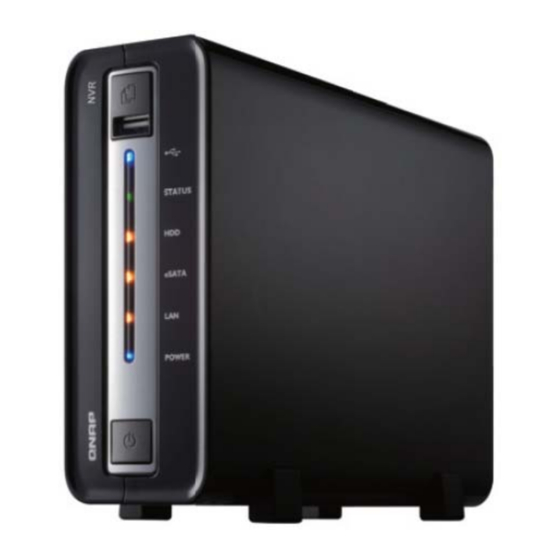
Page 87: Appendix B Led Indication
Appendix B LED Indication NVR provides LED indicators for you to indicate system status and information easily. 1. USB Status 2. System Status 3. HDD 4. eSATA HDD 5. LAN 6. Power When the system is turned on, you will see the following LED indication: The power LED will become blue;... - Page 88 LED Display & System Status Overview LED Display & System Status Power Blue: Power is on Blink in orange when accessing network HDD1/eSATA Blink in orange when accessing the disk(s) Green: System is started and ready Blink in green: No hard disk is detected. Blink in green for 5 seconds, then blink in green and red System Status alternatively: Hard disk not initialized...
-
Page 89: Appendix C Dynamic Domain Name Registration
Appendix C Dynamic Domain Name Registration NVR supports DDNS service provided by DynDNS. You can go to DynDNS website http://www.dyndns.org/ to register a dynamic domain name. Configure and activate DDNS service to enable the Internet users to access your NVR via this dynamic domain name. When the ISP assigns a new WAN IP address, NVR will update the new address to the DynDNS server automatically. - Page 90 Registration Procedure Please follow the steps below to register a dynamic domain name. This guide is for reference only. If there are any changes, please refer to the instructions or documents on the web site. Open the browser and connect to http://www.dyndns.com/. Click Create Account to begin registration.
- Page 91 Enter the user name, email address, and password to create an account for DDNS service. Please verify your email address to receive the confirmation message from the server. Select to accept the terms of service.
- Page 92 Configure the mailing lists if necessary. Then click Create Account. When your account is successfully created, a confirmation message will be sent to your e-mail address. Please follow the instructions in the e-mail to activate your account within 48 hours. When you have finished the confirmation process, you can apply for your own dynamic domain name.
-
Page 93: Appendix D Product Specifications
Appendix D Product Specifications Software Specification Video Display Mode Single, quad, Picture-in-Picture, Sequential mode Recording Cameras Up to 4 Compression Format Motion JPEG/ MPEG 4 (depend on IP Camera) Video Setting Resolution, Quality, Frame Rate E-map Upload E-map Recording Recording Mode Continuous, manual, scheduled, alarm, motion, snapshot Buffer Storage for Pre-recording: 300 Seconds/ Post–recording :300 Seconds... - Page 94 Gross weight: 1.57 Kg (without HDD) Temperature 0~35°C Humidity 0%~85% R.H. Power Supply 36W, 100~240V K-Lock Security Slot for Theft Prevention, Power cord hook Secure Design for kicking-off prevention *Designs and specifications are subject to change without notice. Please contact QNAP for updated information.
-
Page 95: Appendix E Network Camera Compatibility List
DCS-900 FCS-1010/WCS-2010 FCS-1040/WCS-2040 FCS-1070/WCS-2070 LevelOne FCS-3000 FCS-1060/WCF-2060 FCS-1030/WCS-2030 FCS-3021 BL-C30 BL-C10 BL-C131 BL-C111 Panasonic Network Camera BL-C20 BL-C1 BL-C11 BL-C31 ICS1003 IPUX Network Camera ICS1013 WVC54GCA Linksys *For the information of supported camera models, please visit QNAP website at http://www.qnap.com/. -
Page 96: Appendix F Configuration Examples
Appendix F Configuration Examples Environment 1: NVR, IP Camera and monitoring PC are all in the same network Network Surveillance Installation for SOHO and SMB IP Address 192.168.1.1 192.168.1.100 Camera 1 192.168.1.101 Camera 2 192.168.1.102 Camera 3 192.168.1.103 In the example, just add the camera to NVR by entering the cameras’ IP address. - Page 97 Environment 2: NVR and IP camera are installed behind the router, while the monitoring PC is located remotely IP Address Mapped port in router 192.168.1.1 8000 Camera 1 192.168.1.101 8001 Camera 2 192.168.1.102 8002 Camera 3 192.168.1.103 8003 Router public IP 219.87.144.205 10.8.10.100...
- Page 98 In this example, to allow a remote PC to connect to NVR and the cameras, you need Step 1. Set up port mapping (virtual server) on the router. From Forward to 219.87.144.205:8000 192.168.1.1:80 219.87.144.205:8001 192.168.1.101:80 219.87.144.205:8002 192.168.1.102:80 219.87.144.205:8003 192.168.1.103:80 Step 2. Add camera to NVR by entering the IP address of the camera in the “IP Address”...
- Page 99 Environment 3: NVR and IP camera are all located remotely IP Address 219.87.144.205 Camera 1 61.62.100.101 Camera 2 61.62.100.102 Camera 3 61.62.100.103 In this example, just add the camera to NVR by adding its IP address to the “IP Address” settings. Note: If there is a particular port for connecting the camera, please specify the port in NVR configuration.
- Page 100 Environment 4: NVR and IP camera are installed behind the router IP Address NVR 1 192.168.1.101 NVR 2 192.168.1.102 NVR 3 192.168.1.103 Router public IP 219.87.145.205 In the example, to allow a PC which is located remotely to access each NVR via FTP, you need to: Step 1.
-
Page 101: Technical Support
Technical Support QNAP provides dedicated online support and customer service via instant messenger. You can contact us by the following means: Online Support: http://www.qnap.com E-mail: q_support@qnap.com MSN: q.support@hotmail.com SKYPE: qnapskype...
Need help?
Do you have a question about the NVR-101 and is the answer not in the manual?
Questions and answers