
Related Manuals for Rosslare AC-525


Summary of Contents for Rosslare AC-525
- Page 1 AC-525 Video Integrated Networked Access Controller Hardware Installation and User Manual June 2008...
-
Page 3: Table Of Contents
1.1 Features..................4 1.2 AxTrax AS-525................5 2. Technical Specifications ............7 3. AC-525 Panel Set-Up ............10 3.1 AC-525 Access Control Panel Diagram ........11 3.2 Inputs Wiring – Non-Supervised Inputs ........12 3.3 Inputs Wiring – Supervised Inputs...........12 3.4 Outputs Wiring ................12 3.5 Power Supply................15 3.6 Reader ..................15... - Page 4 Table of Contents 6.3 Modem Network Connection...........36 Appendix A. AS-525 Web Server ........37 Appendix B. Limited Warranty ..........47 Appendix C. Technical Support ..........49 AC-525 Hardware Installation and User Guide Page iii...
-
Page 5: Introduction
When used in combination with Rosslare's AS-525AV ViTrax and AxTrax software systems, the AC-525 gives you full control over the entrances to your premises. The system can control both single and double door entrances, or up to 4 doors using the MD-D02 reader expansion board. It supports up to 30,000 users and uses flash memory to enable easy firmware upgrades. -
Page 6: Axtrax As-525
The AxTrax AS-525 software system is custom designed to set-up, manage and supervise all aspects of an access panel network. It offers the following capabilities: User capacity 30000 Access groups 30000 Number of panels in system 1023 Page 5 AC-525 Hardware Installation and User Guide... - Page 7 AxTrax AS-525 supports several access control panel types including the AC-525, and offers scalability and flexibility in addition to a range of advanced control features. Configurable Links The system's configurable links model makes it possible to automatically trigger any chosen input, output, or event.
-
Page 8: Technical Specifications
Image size, compression, fps, superimposed details Data management Backup, FLASH Firmware, History Event Log and Audit Trail IP Streaming Cient Customized Low Latency Streaming Client (VLC) Security Multiple Authentication levels for users – Basic Encryption Page 7 AC-525 Hardware Installation and User Guide... - Page 9 30,000 Users per door High Speed < 1 s Authentication time for Full Load Time Zones and Groups 32 multiple segment time zones, 64 holidays, unlimited access group levels Networking 32 Unit/subnets, 1023 subnets AC-525 Hardware Installation and User Guide Page 8...
- Page 10 9.92 lbs (4.5 kg) Transformer AC Transformer 120/220V AC/16V AC 2.5A (40VA) Class 2 Power Supply Specifications Input Voltage 16V AC / 2.5A Power LEDs Power In (AC) Red LED8 Main power Page 9 AC-525 Hardware Installation and User Guide...
-
Page 11: Ac-525 Panel Set-Up
AC-525 Panel Set-Up AC-525 Panel Set-Up Every AC-525 panel controls two doors. The panels connect together in a network and are controlled by a central server computer, running the AS- 525AV AxTrax software system. The following diagram shows an example set-up for the AC-525 access control panel configuration. -
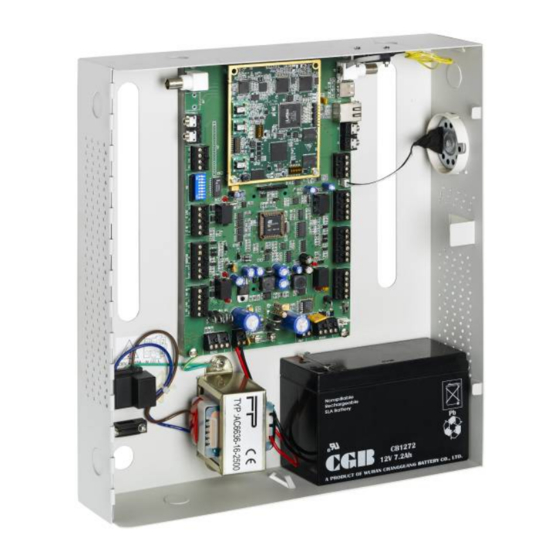
Page 12: Ac-525 Access Control Panel Diagram
IN 2 LINE OUT 1 LINE RESET IN 1 LED1 LED2 I/O BOARD READER1 READER2 LED2 LED1 LED3LED4LED8 LED5 LED6 L2 L1 16VAC VBAT RS485 MD-14 JP10 Figure 2: AC-525 Access Control Panel Page 11 AC-525 Hardware Installation and User Guide... -
Page 13: Inputs Wiring - Non-Supervised Inputs
Figure 3: Inputs Wiring – Non-supervised Inputs Inputs Wiring – Supervised Inputs When wiring the AC-525 for supervised inputs, resistors should be placed on the input switch and not on the terminal block. For further details refer to Input and Output Requirements on page 18. - Page 14 AC-525 Panel Set-Up Figure 4: Door Lock – Failed Close Page 13 AC-525 Hardware Installation and User Guide...
- Page 15 AC-525 Panel Set-Up Figure 5: Door Lock – Failed Open AC-525 Hardware Installation and User Guide Page 14...
-
Page 16: Power Supply
Note: When extending the cable distance, be careful with the color of the cable cover. Refer to the reader specifications for the maximum cable length (typically 150m with an 18 AWG cable). Page 15 AC-525 Hardware Installation and User Guide... -
Page 17: Video
AC-525 Panel Set-Up Figure 7: Wiring the Reader Video To connect the AC-525 to the two video cameras, a BNC to BNC cable is needed. An Ethernet cable connects the panel (RJ45) to the Ethernet. For each camera, there is an optional microphone in and speaker out. -
Page 18: Md-Io84
The MD-D02 is an optional Reader expansion board which adds 2 readers, four relay outputs and four supervised inputs to the Access Control Panel. Attach the MD-D02 to the AC-525's expansion slot, as marked in red in the figure 9, below. -
Page 19: Input And Output Requirements
Input and Output Requirements Input and Output Requirements This chapter describes the AC-525 access control panel's input and output requirements. Input Types There are six input types – Normally Open, Normally Closed, Normally Open Supervised 1 or 2 resistors, and Normally Closed Supervised 1 or 2 resistors. - Page 20 Normally Closed Input Connection: Normally Closed Input has two states: • Switch Closed – Normal State: Loop resistance = 0 (short circuit) • Switch Open – Abnormal State: Loop resistance = Infinite (open circuit) Page 19 AC-525 Hardware Installation and User Guide...
- Page 21 Switch Open – Normal State: Loop resistance = 8.2K • Switch Closed – Abnormal State: Loop resistance = 0 (short circuit) • Open circuit across input terminals – Trouble State: Loop resistance = Infinite (open circuit) AC-525 Hardware Installation and User Guide Page 20...
- Page 22 1) Switch Open – Normal State: Loop resistance = 8.2K 2) Switch Closed – Abnormal State: Loop resistance = 2.2K 3) Open circuit (Infinite loop resistance) or short circuit (0 resistance) across input terminals – Trouble State Page 21 AC-525 Hardware Installation and User Guide...
- Page 23 Switch Closed – Normal State: Loop resistance = 2.2K • Switch Open – Abnormal State: Loop resistance = Infinite (open circuit) • Short circuit across input terminals – Trouble State: Loop resistance = 0 (short circuit) AC-525 Hardware Installation and User Guide Page 22...
- Page 24 Switch Closed – Normal State: Loop resistance = 2.2K • Switch Open – Abnormal State: Loop resistance = 10.4K • Open circuit (Infinite loop resistance) or short circuit (0 resistance) across input terminals – Trouble State Page 23 AC-525 Hardware Installation and User Guide...
-
Page 25: Inputs Description
Door 2 -IN2 Door 3 -IN5 Door 4 -IN7 Door Monitor Input The Door Monitor Input typically connects to a Normally Closed door sensing micro-switch for door status monitoring. Using Door Monitor AC-525 Hardware Installation and User Guide Page 24... -
Page 26: Outputs
IN5 to IN12 MD-D02: IN5 to IN8 except the dedicated inputs Outputs Rosslare Security recommends the use of suppression diodes for all outputs that activate an inductive load. Door Lock There are two types of door locking devices: • Fail open (fail secure) •... -
Page 27: Card Readers And Keypads
OUT7 = door4 The output can sink current from any power supply (see page 16). An AC-525 output can provide 12 VDC power up to 1A for external door locks. For higher rated door locks an external UL 294 Listed power supply must be used to provide power to the door lock. -
Page 28: Video Card
Dipswitch 1: For the manufacturer. Must always be off. • Dipswitch 2: Off – Normal Operation. On – Reset for functional default. On the bottom of the video card is a reset button for the video. Page 27 AC-525 Hardware Installation and User Guide... -
Page 29: Ac-525 Hardware Settings
AC-525 Hardware Settings AC-525 Hardware Settings Each AC-525 panel controls an entrance. The behavior of the panel is controlled by Dipswitch settings. Select the appropriate Dipswitch setting to operate the panel as either a single door, a double door, or four doors. See below Access Control Panel Type, page 31. - Page 30 Door3 Request to exit (IN 5) Door3 monitor input (IN 6) Door4 Request to exit (IN 7) Door4 monitor input (IN 8) Readers Reader1 (Door1 IN/OUT) Reader2 (Door2 IN/OUT) Reader3 (Door3 IN/OUT) Reader4 (Door4 IN/OUT) Page 29 AC-525 Hardware Installation and User Guide...
-
Page 31: Dipswitch Configuration
Dipswitch settings. After changes have been made, restart the panel. The new settings are automatically defined after power up. Panel power up time is 1 to 2 minutes long due to the Video Module start-up duration. AC-525 Hardware Installation and User Guide Page 30... -
Page 32: Access Control Panel Baud Rate
The default access control panel setting is for two readers per each door. 1 2 3 4 5 6 7 8 Figure 18: Dipswitch with Single Door Setting Dipswitch position MD-D02 Panel Type 2 readers, 1 door Page 31 AC-525 Hardware Installation and User Guide... -
Page 33: Access Control Panel Addressing
The default access control panel address is “1”. 1 2 3 4 5 6 7 8 Figure 19: Dipswitch with Internal Network Address Setting Note: For successful communications, the Dipswitch must match the address set in the AS-525 software. AC-525 Hardware Installation and User Guide Page 32... - Page 34 AC-525 Hardware Settings The following table displays the 32 Dipswitch settings available: Address Switch 4 Switch 5 Switch 6 Switch 7 Switch 8 Page 33 AC-525 Hardware Installation and User Guide...
-
Page 35: Communications
4000 feet (~1300meters). The data line wiring must be in daisy chain formatting with one control unit following another. The first Access control panel connecting to the PC must use the MD-14 RS485 to RS232 adaptor. AC-525 Hardware Installation and User Guide Page 34... -
Page 36: Tcp/Ip Network Connection
The computer running the AS-525 software can communicate with the access control panels via a TCP/IP network. The connection settings are controlled within the AS-525 software. AC-525 panels connect to the TCP/IP network (LAN or WAN) directly, using the video module. Page 35... -
Page 37: Modem Network Connection
Converter Converter RS232 Telephone Line Access RS232 Control Panel RS485 MD-14 RS232/RS485 Converter Figure 21: Remote Site Modem Configuration Note: For more information on modem connections, refer to the MD-N33 User Manual. AC-525 Hardware Installation and User Guide Page 36... -
Page 38: Appendix A. As-525 Web Server
Communications Appendix A. AS-525 Web Server The AC-525 comes with a video server that enables the installation technician to control settings of the video cameras and set defaults for the recordings. To access the AS-525 Video Server: Type the AC-525’s panel IP address into the browser. The Admin Login screen appears. - Page 39 From the menu on the left side of the screen, click on Video & Image. The Video & Image screen appears. Figure 25: Video & Image Screen Adjust resolution, source frame rate, target frame rate, and maximum bit rate. AC-525 Hardware Installation and User Guide Page 38...
- Page 40 Click Submit for the changes to take effect. From the menu on the left side of the screen, click Date & Time. The Date & Time screen appears. Figure 26: Date & Time Screen Page 39 AC-525 Hardware Installation and User Guide...
- Page 41 VeriTrax. Click Submit for the changes to take effect. 13. From the menu on the left side of the screen, click I/O Ports. The I/O Ports screen appears. AC-525 Hardware Installation and User Guide Page 40...
- Page 42 UART0 and UART1 are only applicable for the PTZ camera (which is not relevant for this version). • UART2 is for AxTrax access control (should be set like Dipswitch No. 1 and 2). Page 41 AC-525 Hardware Installation and User Guide...
- Page 43 Camera #1 can be adjusted. Click Submit for the changes to take effect. 17. From the menu on the left side of the screen, click Cam #2. The Camera #2 screen appears. AC-525 Hardware Installation and User Guide Page 42...
- Page 44 19. From the menu on the left side of the screen, click Remote MIC. The Remote MIC screen appears. Figure 31: Remote MIC Screen 20. Type in the IP address of the remote microphone. Page 43 AC-525 Hardware Installation and User Guide...
- Page 45 USB. In this case, there is no USB being used. 24. From the menu on the left side of the screen, click Local Storage Content. The Local Storage Content screen appears. Figure 33: Local Storage Content Screen AC-525 Hardware Installation and User Guide Page 44...
- Page 46 File. The Update – Step 2 screen appears. Figure 35: Update Step 2 Screen 28. Confirm that the correct file was chosen. Click Update. The Update-Step 3 screen appears. The word Finished confirms that the file was successfully uploaded. Page 45 AC-525 Hardware Installation and User Guide...
- Page 47 Communications Figure 36: Update Step 3 Screen Note: The AC-525 video panel has to be rebooted in order for the new firmware to take effect. AC-525 Hardware Installation and User Guide Page 46...
-
Page 48: Appendix B. Limited Warranty
2 years (24 Months). Warranty Remedy Coverage In the event of a breach of warranty, ROSSLARE will credit Customer with the price of the Product paid by Customer, provided that the warranty claim is delivered to ROSSLARE by the Customer during the warranty period in accordance with the terms of this warranty. -
Page 49: Limited Warranty
This warranty shall not extend to any ancillary equipment not furnished by ROSSLARE, which is attached to or used in conjunction with a Product, nor to any Product that is used with any ancillary equipment, which is not furnished by ROSSLARE. -
Page 50: Appendix C. Technical Support
Tel: +972 3 938-6838 Fax: +972 3 938-6830 E-mail: support.eu@rosslaresecurity.com South America Pringles 868, 1640 Martinez Buenos Aires Argentina Tel: +54 11 4798-0095 Fax: +54 11 4798-2228 E-mail: support.la@rosslaresecurity.com Web Site: www.rosslaresecurity.com Page 49 AC-525 Hardware Installation and User Guide... - Page 52 www.rosslaresecurity.com...
Need help?
Do you have a question about the AC-525 and is the answer not in the manual?
Questions and answers