
Related Manuals for Rosslare AY-Q65


Summary of Contents for Rosslare AY-Q65
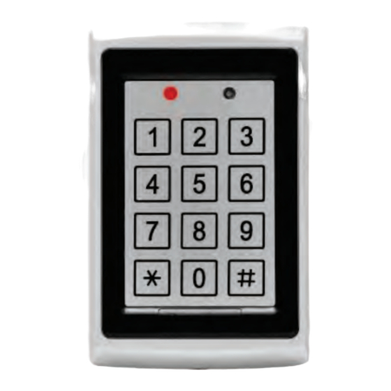
- Page 1 2012 June AY-Q65 Anti-Vandal Piezo PROX & PIN Reader Installation and Programming Manual...
- Page 2 ROSSLARE. ROSSLARE reserves the right to revise and change this document at any time, without being obliged to announce such revisions or changes beforehand or after the fact.
-
Page 3: Table Of Contents
Table of Contents Introduction ..............7 Technical Specifications ..........8 Key Features .............. 10 Installation ..............11 Mounting the AY-Q65 ............11 Wiring the AY-Q65 ............... 12 Transmit Mode ............13 Programming the AY-Q65 ......... 14 Entering Programming Mode ..........15 Exiting Programming Mode ........... - Page 4 List of Figures List of Figures Figure 1: Drill Holes for AC-Q65 Controller ............. 11 AY-Q65 Installation and Programming Manual...
- Page 5 List of Tables List of Tables Table 1: Wire Color Guide ................12 Table 2: Programming Menus................14 Table 3: Keypad Transmission Format .............. 17 AY-Q65 Installation and Programming Manual...
- Page 6 The use of the software associated with the system and/or product, if applicable, is subject to the terms of the license provided as part of the purchase documents. ROSSLARE ENTERPRISES LIMITED and/or its related companies and/or subsidiaries’ (hereafter:"ROSSLARE") exclusive warranty and liability is limited to the warranty and liability statement provided in an appendix at the end of this document.
-
Page 7: Introduction
Introduction Introduction The AY-Q65 is a vandal resistant programmable Wiegand and Clock & Data proximity card and piezoelectric keypad reader. The AY-Q65 supports multiple Proximity Card and Keypad formats providing a high level of compatibility and connectivity with host controllers. -
Page 8: Technical Specifications
LED Control Input Dry Contact, N.O. Tamper Output Open Collector, active low, maximum sink current is 32 mA * Measured using Rosslare Proximity Card (AT-11/14) or equivalent. Range also depends on electrical environment and proximity to metal AY-Q65 Installation and Programming Manual... - Page 9 Operating Humidity 0 to 95% (non-condensing) Suitable for outdoor use (meets IP65) Dimensions Length x Width x Depth 4.72 x 3 x 0.85 in. (120 x 76 x 22 mm) Weight 0.97 lb (440 g) AY-Q65 Installation and Programming Manual...
-
Page 10: Key Features
Programmable Facility Code Two tri-colored LEDs Internal buzzer provides audible interface feedback. Comes with mounting template for easier installation Comes with installation kit that includes a security screw and a security screw tool. AY-Q65 Installation and Programming Manual... -
Page 11: Installation
3. Screw the AY-Q65 back cover to its mounting location. 4. Return the front cover of the AY-Q65 to the mounted back plate. 5. Secure the front cover by using the supplied security screw in the Installation Kit. -
Page 12: Wiring The Ay-Q65
Data 0 / Data BROWN LED Control PURPLE Tamper 3. If the tamper output is being utilized, connect the purple wire to the correct input on the controller. 4. Trim and cover all conductors that are not used. AY-Q65 Installation and Programming Manual... -
Page 13: Transmit Mode
Transmit Mode Transmit Mode When the AY-Q65 is in Transmit mode, it is ready to receive data from a presented Proximity card or an entered PIN code. Transmit Program When the reader is in Transmit Mode, the Transmit LED is red and the Program LED is off. -
Page 14: Programming The Ay-Q65
Programming the AY-Q65 Programming the AY-Q65 Programming the AY-Q65 is done solely via the unit's keypad driven programming menu system. To reach the programming menu system, the AY-Q65 must first be placed into Programming mode (see Section 6.1). During the AY-Q65's manufacturing process, certain codes and settings are pre-programmed. -
Page 15: Entering Programming Mode
The Program LED turns off and the Transmit LED turns red. This indicates that the AY-Q65 has returned to Transmit mode. Wrong entries may reset the reader back to Transmit mode. While in Programming mode, if no key is pressed for 30 seconds, the AY-Q65 exits Programming mode and returns to Transmit mode. -
Page 16: Keypad Transmission Format Option Number
PIN code. 6.3.1 K eypad Transmission Format Option Number 1 6 B See Table 3 to determine the option number for the Keypad Transmission Format you wish to select. AY-Q65 Installation and Programming Manual... - Page 17 Table 3: Keypad Transmission Format Keypad Transmission Format Option Number Single Key, Wiegand 6-Bit (Rosslare Format) Single Key, Wiegand 6-Bit with Nibble + Parity Bits Single Key, Wiegand 8-Bit, Nibbles Complemented 4 Keys Binary + Facility code, Wiegand 26-Bit 1 to 5 Keys + Facility code, Wiegand 26-Bit...
- Page 18 (EP) FFFF FFFF AAAA AAAA AAAA AAAA (OP) Where: EP = Even parity for first 12 bits. OP = Odd parity for last 12 bits F = 8-Bit Facility Code A = 24-Bit code generated from keyboard AY-Q65 Installation and Programming Manual...
- Page 19 Each key is a four bit equivalent of the decimal number. The keypad PIN code must be 6 key presses long. On the sixth key press of the 6-digit PIN code, the data is sent across the Wiegand Data lines as a BCD message. AY-Q65 Installation and Programming Manual...
- Page 20 Q65 keypad while still keeping the proximity card readers 26-Bit Wiegand or Clock & Data formats active. An optional interface board must be used between the AY-Q65 and the host system. Each key press is immediately sent on DATA0 as an ASCII character at a baud rate of 9600 bits per second.
-
Page 21: Selecting Proximity Card Transmission Format
PIN code. Selecting Proximity Card Transmission Format The AY-Q65 has two different selectable proximity card transmission formats. Option 1 – 26-Bit Wiegand ... -
Page 22: Proximity Card Transmission Format Option Number
3. Enter the new 4-digit code you wish to set as the Programming code. Three beeps are emitted on success. The system returns to Transmit mode. Transmit Program The Program LED turns off and the Transmit LED remains red. AY-Q65 Installation and Programming Manual... -
Page 23: Changing The Facility Code
In addition, all codes are returned to their factory default settings. To return to factory default settings: 1. Enter Programming mode. Program Transmit Green AY-Q65 Installation and Programming Manual... -
Page 24: Replacing A Lost Programming Code
Normal mode without erasing the memory of the controller Replacing a lost Programming Code In the event that the Programming code is forgotten, the AY-Q65 may be reprogrammed in the field using the following instructions: 1. Remove power from the reader. -
Page 25: Limited Warranty
ARRANTY EMEDY OVERAGE In the event of a breach of warranty, ROSSLARE will credit Customer with the price of the Product paid by Customer, provided that the warranty claim is delivered to ROSSLARE by the Customer during the warranty period in accordance with the terms of this warranty. Unless otherwise requested by a ROSSLARE representative, return of the failed product(s) is not immediately required. - Page 26 ROSSLARE or a ROSSLARE authorized service center. XCLUSIONS AND IMITATIONS ROSSLARE shall not be responsible or liable for any damage or loss resulting from the operation or performance of any Product or any systems in which a Product is incorporated. This warranty shall not...
- Page 27 In no event shall ROSSLARE be liable for damages in excess of the purchase price of the product, or for any other incidental, consequential or special damages, including but not limited to loss of...
- Page 28 Rosslare Enterprises Ltd. support.la@rosslaresecurity.com Kowloon Bay, Hong Kong Tel: +852 2795-5630 China Fax: +852 2795-1508 support.apac@rosslaresecurity.com Rosslare Electronics (Shenzhen) Ltd. Shenzhen, China United States and Tel: +86 755 8610 6842 Canada Fax: +86 755 8610 6101 support.cn@rosslaresecurity.com Rosslare Security Products, Inc.
Need help?
Do you have a question about the AY-Q65 and is the answer not in the manual?
Questions and answers