Table of Contents
Advertisement
Advertisement
Table of Contents

Related Manuals for Rosslare MD-N32


Summary of Contents for Rosslare MD-N32
- Page 1 MD-N32 Serial to Ethernet Gateway Installation and Operating Guide...
- Page 2 ROSSLARE. ROSSLARE reserves the right to revise and change this document at any time, without being obliged to announce such revisions or changes beforehand or after the fact.
-
Page 3: Table Of Contents
Table of Contents Introduction ..............7 Specifications .............. 8 Connection and Configuration ........9 Hardware Requirements ............9 Software Requirements ............9 Connecting the MD-N32 ............9 3.3.1 Network Connection ..............10 3.3.2 Serial Connection ................. 10 3.3.3 Power Connection ................ 11 3.3.4... - Page 4 List of Figures List of Figures Figure 1: Front View of the MD-N32 ............... 10 Figure 2: Rear View of the MD-N32 ..............10 Figure 3: TCP/IP Network Connection .............. 11 Figure 4: AS-IP01 Configuration Utility GUI ............. 12 Figure 5: AS-IP01 Configuration Utility – Search Button Results ....... 16...
-
Page 5: List Of Tables
List of Tables List of Tables Table 1: AS-IP01 Configuration Utility Buttons ..........13 Table 2: Network Section Fields ............... 13 MD-N32 Installation and Operation Manual... - Page 6 ROSSLARE exclusive warranty and liability is limited to the warranty and liability statement provided in an appendix at the end of this document.
-
Page 7: Introduction
Introduction Introduction The MD-N32 is a Serial to Ethernet Gateway. One MD-N32 unit is required (unless it is connected to a Rosslare software product that supports direct TCP/IP operation, in which case the PC's internal LAN card may be used). -
Page 8: Specifications
0°C to 70°C (32°F to 158°F) Operating Humidity Range 10 to 90% (non-condensing) Dimensions Height x Width x Depth 110 x 63 x 39 mm (4.33 x 2.48 x 1.54 in.) Weight 92 g (3.25 oz) MD-N32 Installation and Operation Manual... -
Page 9: Connection And Configuration
The PC must have a LAN network connection to configure the MD- N32. Both the PC and external unit must be connected to the same LAN through a hub. It is also possible to use the MD-N32 over a WAN, but this requires network router settings. (It is recommended that system administrators be responsible for setting network routers.) -
Page 10: Network Connection
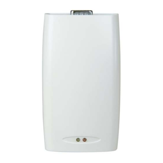
Figure 2: Rear View of the MD-N32 D9-RS-232 Jack 3.3.2.2 PC Side If the MD-N32 is connected to the PC’s serial port, connect the MD- N32's D9 jack to the PC using a cross-linked RS-232 cable. MD-N32 Installation and Operation Manual... -
Page 11: Power Connection
Connection and Configuration 3.3.3 Power Connection Connect a 12 VDC (200 mA) power adaptor to each MD-N32 unit. Ensure that the MD-N32 Power LED is on. 3.3.4 Network Connection Diagram Figure 3 shows the network connection using an MD-N32 and PC network card. -
Page 12: Mac Address Table
When the MD-N32 units connected to the network are found, the units are displayed as MAC addresses in the table. The MAC number is a long 12-digit number that can be found on a sticker located on the bottom side of the MD-N32 unit. MD-N32 Installation and Operation Manual... -
Page 13: Buttons
The results are displayed as MAC addresses in the table. Apply Clicking Apply changes the configuration of the selected MD-N32 unit; the selected unit is initialized with the newly entered values. About Clicking About displays the details of the AS-IP01 Configuration Utility. -
Page 14: Device Type
If not, a connection may be initiated to the server IP and port, and the data may then be resent. 3.4.4 Device Type This section contains the name of the product (MD-N32). 3.4.5 Serial Speed This section lists the product’s speed, which can be configured as desired. -
Page 15: Status
The inactivity time is intended for use with the TCP channel when a link is established. If the inactivity timer has expired, the channel is closed to data transfer. Data transfer resumes once the MD-N32 has been set to the client. The inactivity timer range may be 0 (the default, TCP channel is always ON) or from 30 to 65,535 seconds. -
Page 16: Figure 5: As-Ip01 Configuration Utility - Search Button Results
For example, it is not recommended to run AS-IP01 on the same PC and at the same time as Rosslare’s AxTraxNG™ software. 4. Select the MAC Address of the MD-N32 unit that is connected to the applicable networked unit. 5. In the Network section, in the Local IP and Local Port text boxes, enter the first IP Address and port number (1000 recommended) supplied by your network administrator. - Page 17 Connection and Configuration 9. Click Apply to send the configuration to the unit. 10. Run the applicable application software for the networked unit. MD-N32 Installation and Operation Manual...
-
Page 18: Limited Warranty
The full ROSSLARE Limited Warranty Statement is available in the Quick Links section on the ROSSLARE website at www.rosslaresecurity.com. Rosslare considers any use of this product as agreement to the Warranty Terms even if you do not review them. MD-N32 Installation and Operation Manual... - Page 19 +86 755 8610 6842 Fax: +86 755 8610 6101 Rosslare Security Products, Inc. support.cn@rosslaresecurity.com Southlake, TX, USA Toll Free: +1-866-632-1101 India Local: +1-817-305-0006 Rosslare Electronics India Pvt Ltd. Fax: +1-817-305-0069 Tel/Fax: +91 20 40147830 support.na@rosslaresecurity.com Mobile: +91 9975768824 Europe sales.in@rosslaresecurity.com Rosslare Israel Ltd.
Need help?
Do you have a question about the MD-N32 and is the answer not in the manual?
Questions and answers