
Related Manuals for Extreme Flight EXTRA 300EXP v2


Summary of Contents for Extreme Flight EXTRA 300EXP v2
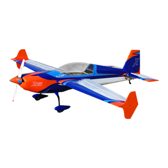
- Page 1 EXTRA 300EXP Electric ARF Copyright Extreme Flight 2020 www.modellmarkt24.ch www.modellmarkt24.ch...
- Page 2 Orange/White/Blue color scheme: Orange, White, Midnight Blue, Sky Blue, Silver Extreme Flight R/C reserves the right to alter the assembly process at any time. While we do our best to update the manuals, sometimes there are minor changes in the process of the build.
- Page 3 Tips for Success: 1. Before starting assembly, take a few minutes to read the entire instruction manual to familiarize yourself with the assembly process. 2. Please take a few minutes and go over all the seams on the aircraft with a covering iron on a medium heat setting.
- Page 4 -Adhesive backed Velcro and Velcro strap for battery retention. Please note: The Extreme Flight 4 in 1 airplane stand is invaluable when assembling our aircraft, from the 48" size models right up to our 50cc models. I can't imagine assembling all of the aircraft I do without the aid of this inexpensive yet handy tool! https://extremeflightrc.com/4-in-1-Airplane-Stand_p_1892.html...
- Page 5 1. Gather the components for the landing gear assembly. 2. Insert the threaded portion of the axle into the carbon fiber landing gear. Slide a washer onto the axle followed by a nylon insert lock nut. Do not tighten yet. 3.
- Page 6 4. Slide the wheel pant into position. Tighten the nut on the axle so that the wheel pant is pinched between the axle and the landing gear leg. The recessed area of the wheel pant will align with the gear and prevent it from rotating. Repeat for the other wheel pant. 5.
- Page 7 7. Secure the radial mount to the motor with the 4 supplied Phillips taper head screws. 8. Secure the prop adapter to the other side of the motor with the supplied socket head cap bolts. Remember to use blue thread lock compound on all bolts! 9.
- Page 8 Use a fine tipped marker to mark the location of the center of each mounting tab. Roll the tape back and slide the cowl into position. Install an Extreme Flight 52mm spinner onto the motor shaft for reference and once satisfied with the cowl position roll the tape back into place and secure the cowl.
- Page 9 12. Locate the horizontal stabilizer/elevator assembly along with the elevator control horn. Verify the fit of the control horn and make sure it does not protrude through the top of the surface. Trim if necessary. Once satisfied scuff the portion of the horn that will be inserted into the elevator with sandpaper. Glue the horn into position in the precut slot with medium CA.
- Page 10 14. Insert the stab into the rear of the fuselage and push as far forward as possible. Slide the main wing tube into its sleeve to check alignment with the stab. Measure side to side as well. When satisfied secure the stab assembly to the fuselage with thin and medium CA.
- Page 11 15. Scuff the rudder horn with sandpaper and glue into the pre-cut slot on the lower portion of the rudder with medium CA. Slide the rudder onto the hinges and secure to the fuselage with thin CA. 16. Secure the tailwheel assembly to the bottom rear of the fuselage with the provided wood screws and affix the tiller arm to the bottom of the rudder with a wood screw.
- Page 12 17. Attach an 18" Extreme Flight 28AWG servo extension to the elevator servo lead and secure with heat shrink tubing or an Extreme Flight servo extension lock. Install the elevator servo into its slot and assemble the linkage as shown. There is a G10 servo arm included in the hardware package, used to achieve 3D throws in excess of 50 degrees.
- Page 13 18. Attach an 18" Extreme Flight 28AWG servo extension to the elevator servo lead and secure with heat shrink tubing or an Extreme Flight servo extension lock. Install the rudder servo and assemble the linkage as shown. The stock servo arm provides full rudder deflection.
- Page 14 21. Insert the aileron servo into position and secure with the manufacturer supplied servo screws or Extreme Flight socket head servo screws. Assemble the aileron linkage as shown. Please note that I have installed the linkage on the bottom side of the servo arm. This reduces the chance of binding and allows full deflection with the stock servo arm.
- Page 15 24. Insert the carbon fiber wing tube into its sleeve in the fuselage and slide the wings into position. Secure each wing by inserting a nylon wing bolt through the fuselage side and into the pre-installed blind nut in each wing root. www.modellmarkt24.ch www.modellmarkt24.ch...
- Page 16 Set-up and flying tips Start by balancing your aircraft on the center of the carbon fiber wing tube. There is plenty of room on the battery tray to move your battery to achieve this CG location. This is a safe place to start and depending on your flying style you can adjust the position of the battery to alter the CG to accommodate your flying style.
- Page 17 Here are some suggested rates to get started with. These are the rates and exponential values I feel comfortable with. They may feel awkward to you and if so please adjust to your taste. Elevator: Low rate-8-10 degrees; 15-20% Exponential 3D rate-45-50 degrees;...
- Page 18 Another neat set-up to try is to mix the ailerons to act as spoilerons which move in conjunction with your elevator. This mix commands both ailerons to raise as the elevator raises. I typically use this mix at 100% and put it on a switch so I can turn it on when needed and inhibit it when not needed.
Need help?
Do you have a question about the EXTRA 300EXP v2 and is the answer not in the manual?
Questions and answers