Advertisement
Quick Links
Advertisement

Related Manuals for Extreme Flight EXTRA 300


Summary of Contents for Extreme Flight EXTRA 300
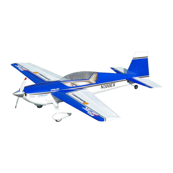
- Page 1 EXTRA 300 ELECTRIC ARF Instruction Manual ©Copyright 2006 EXTREME FLIGHT RC, Ltd.
- Page 2 As with all Extreme Flight RC airplanes, the proof is in the flying! Due to the close proximity of the wing and stab to the thrust line, the Extra 300 is a very neutral flying aircraft. It flies precision aerobatics remarkably well and allows you to practice your IMAC sequence almost anywhere.
-
Page 3: Wing Assembly
Wing assembly 1. Locate a wing panel. Check to see that all hinges are centered between the wing and aileron. Hold the aileron fully deflected and apply a drop of thin CA to each hinge. Flip the wing over and repeat. 2. - Page 4 3. Locate the composite aileron control horn, aileron pushrod with z-bend and ez- connector. Remove the covering over the mounting hole for the control horn with your #11 blade. Glue the control horn in place with medium CA. Electronically center your servo and mount the ez-connector to the servo arm. Place the z-bend in the aileron control horn and the other end of the wire into the hole in the ez- connector.
- Page 5 Fuselage Assembly 1. Lets mount the landing gear first. Locate the aluminum landing gear, (4) 3mm machine screws ( 2 long, 2 short), (4) wheel collars, the two wheel pants and wheels and the 2 small plywood squares. Use medium CA to glue the plywood square to the inside of each wheel pant, centered in the wheel pant opening.
- Page 6 3. Apply a drop of loc-tite to each screw and insert it through the landing gear and into the pre-installed blind nut in the landing gear plate.
- Page 7 4. Locate the motor box assembly and the 2 laser cut triangular motor box supports. Place the tabs in the motor mount assembly into the firewall and push down so that they lock into place. Install the triangular supports as shown. Wick thin and medium CA into all joints and allow to cure.
- Page 8 6. Position the canopy/hatch in place and slide the cowl over the first former. Use your spinner (a 2” spinner is the proper size) on the prop shaft to make sure the cowl is aligned properly. View the cowl from the side and top view to insure it is positioned properly.
- Page 9 8. After it is dry, flip the elevator over so that the counterbalances are facing the rear of the plane. Insert the elevator into the slot. Once it is in position, insert the horizontal stab into place. Re-check alignment and when satisfied, glue the stabilizer in place with CA or a small amount of epoxy.
- Page 10 picture and secure with a small piece of strapping tape. Slide the rudder into position and glue the hinges in place with thin CA. 11. Locate the elevator control horn and glue in place with medium CA or epoxy. Use a #11 blade to remove the covering from the elevator servo slot and install the servo using the manufacturer supplied mounting hardware.
- Page 11 12. Mount the rudder servo as shown inside the fuselage. We highly recommend using a more powerful servo for the rudder such as the Hitec HS-56, HS-65 or JR 281 to prevent control surface blow back. Use the supplied hardware to assemble the pull-pull cable system.
- Page 12 Velcro strap around the battery. 11. Use the supplied nylon bolts to secure the wings to the fuselage. This concludes the assembly of the Extra 300. Radio Set-up and flight tips. CG range for the Extra is from 3.50”- 4.00” from the leading edge of the wing measured at the wing root.
Need help?
Do you have a question about the EXTRA 300 and is the answer not in the manual?
Questions and answers