
Related Manuals for Toshiba digital copiers


Summary of Contents for Toshiba digital copiers
- Page 1 G A - 1 1 2 1 S E R V I C E G U I D E f o r To s h i b a d i g i t a l c o p i e r s A g u i d e f o r s e r v i c e t e c h n i c i a n s Part Number: 45040232 9 February 2004...
- Page 3 Copyright © 2004 Electronics for Imaging, Inc. PANTONE® Colors displayed in the software application or in the user documentation may not match PANTONE-identified standards. Consult current PANTONE Color Publications for All rights reserved. accurate color. PANTONE® and other Pantone, Inc. trademarks are the property of Pantone, Inc.
- Page 4 You may not make or have made, or permit to be made, any copies of the Software or portions Limitation of Liability thereof, except one (1) copy for backup or archive purposes in support of your use of the TO THE MAXIMUM EXTENT PERMITTED BY LAW, EFI AND ITS SUPPLIERS SHALL Software as permitted hereunder.
-
Page 5: Table Of Contents
Contents Preface About this guide About the illustrations in this guide Terminology and conventions viii Precautions viii Tools you will need Chapter 1: Introduction Features How the GA-1121 operates GA-1121 print options User software Fiery WebTools Chapter 2: Using the GA-1121 Control Panel Status/Control overview Activity light Buttons... - Page 6 Contents System software 3-23 System software installation reminders 3-23 Installing system software 3-24 Chapter 4: Troubleshooting The troubleshooting process Preliminary on-site checkout Checking external connections Checking internal connections Inspecting the system Normal startup sequence Error messages and conditions Diagnostic tools 4-13 Video diagnostics 4-13...
-
Page 7: About This Guide
About this guide The Service Guide is intended for certified TOSHIBA GA-1121 (Fiery X3e+) and copier Preface service technicians servicing a GA-1121. If you have not received installation and service certification, you should not attempt to install or service a GA-1121. Electronics for Imaging, Inc. -
Page 8: Terminology And Conventions
Preface Terminology and conventions The term “network administrator” refers to the person responsible for maintaining the network at the customer site. The term “Control Panel” describes the separate GA-1121 Control Panel attached to the front of the copier. It includes an LED, a display window, and several control buttons. The term “PC”... - Page 9 Precautions • Never enter an IP address in Network Setup. Only the network administrator should enter an IP address on a network device. Assigning an incorrect IP address to the GA-1121 can cause unpredictable errors on any or all devices. •...
-
Page 10: Tools You Will Need
Preface Tools you will need To service the GA-1121, you should bring the following: • ESD wrist grounding strap • Antistatic mat • #1 and #2 Phillips head screwdrivers (non-magnetic) • Small needlenose pliers • Flashlight • This guide and any technical notes you may have for the GA-1121... -
Page 11: Chapter 1: Introduction
Features The GA-1121 provides highly efficient color printing capability for the copier. Chapter 1: Users can print from networked PCs running Windows 9x/Me, Windows NT or Introduction Windows 2000/XP, and from networked Mac OS computers. Features As an integral part of the printing system, the GA-1121 enables users to: •... -
Page 12: How The Ga-1121 Operates
Introduction How the GA-1121 operates The GA-1121 provides efficient image processing and printing control. The GA-1121 board includes a 850MHz Intel Pentium III CPU with a built-in floating point accelerator that runs the PostScript Interpreter, which interprets the page description file ™... -
Page 13: Ga-1121 Print Options
User software GA-1121 print options The efficient PostScript capabilities of the GA-1121 allow customers to use a variety of applications to create printed color pages of text and/or images. Since the GA-1121 has ® the ability to print an image while processing the next image (RIP-While-Print ), it is capable of printing documents at full copier speeds. - Page 14 Introduction Command WorkStation Allows the operator to manage job flow and control (Windows only) GA-1121 functions from remote workstations. For more information, see the Job Management Guide. Command WorkStation LE Allows the operator to manage job flow and control (Mac OS 10.2.3 or later) GA-1121 functions from remote Mac OS computers.
-
Page 15: Fiery Webtools
User software Fiery WebTools The GA-1121 can support Internet or intranet access with EFI Fiery WebTools ™ , which include Status, WebLink, Installer, WebDownloader, WebScan, and WebSetup. For more information on WebTools, see the GA-1121 user documentation. -
Page 17: Status/Control Overview
Status/Control overview This section describes the GA-1121 functions on the Control Panel. The GA-1121 Chapter 2: Control Panel is separate from the copier Operation Panel and is located on the left side Using the of the copier. You will use the buttons on the Control Panel to access and monitor GA-1121 different features of the GA-1121. -
Page 18: Buttons
Using the GA-1121 Control Panel Buttons The control buttons on the GA-1121 Control Panel allow you to navigate the various screens and to send commands. Usually, the display window shows the name of the screen on the first line and one menu item or message on the second line. The buttons perform the following functions: Buttons Description... -
Page 19: Screens
Screens Screens While one or more jobs are being sent to the GA-1121, runtime information is displayed on the GA-1121 Control Panel. If an Alert condition arises, the Alert screen is displayed. Pressing the Menu button moves from the Idle screen to any active runtime screens (RIP, Print, Alert) and then to the Functions screen. - Page 20 Using the GA-1121 Control Panel These screens contain the following information: status screen The first line of this screen displays the status of Idle the GA-1121. The status can be Info, Processing, Info Server Name Printing, Error, or Offline. The second line of the XXXX MB screen displays the copier’s name on the network.
-
Page 21: Functions Screen
Screens Functions screen The Functions screen allows you to perform a variety of administrative functions that do not affect print jobs of other users. To access the Functions screen, press the Menu button. Use the up/down arrow buttons to scroll through the list of menu items. Press the Set button when the option you want to select is displayed. - Page 22 Using the GA-1121 Control Panel Resume Printing —Resumes printing after interrupting the print job in order to make copies. Shut Down —When you select this option, you can choose from the following:. • Restart Server —Resets the GA-1121 system software but does not reboot the entire system.
-
Page 23: Config Mode
Config Mode Config Mode The GA-1121 Control Panel provides a Config Mode screen which lets you perform special functions such as clearing all jobs on the GA-1121, installing system software, and viewing system software version information. O USE ONFIG ODE FUNCTIONS 1. -
Page 24: Restarting The Ga-1121
Using the GA-1121 Control Panel GA-1121 O SHUT DOWN THE 1. Make sure that no jobs are being processed or printed (the activity light should be off). 2. Press the Menu button on the Control Panel to access the Functions menu. 3. -
Page 25: Chapter 3: Service Procedures
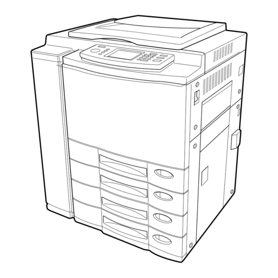
Overview Generally, the GA-1121 assembly does not require regular maintenance. Use the Chapter 3: procedures in this chapter to inspect, remove, reseat, or replace major hardware Service components. This chapter also describes how to install system software on the GA-1121. Procedures Overview This chapter includes information on the following:... - Page 26 Service Procedures 1. Faceplate 2. Tray 3. GA-1121 board 4. Hard disk drive 5. HDD power cable 6. HDD cable 7. Battery 8. DIMM(s) 9. CPU assembly 10. Copier interface connector 11. Intake fan 1 12. Intake fan 2 13. Power supply cable 14.
-
Page 27: Ga-1121 Assembly
GA-1121 assembly GA-1121 assembly The GA-1121 board has a 850MHz CPU that controls the video image data transferred to and from the copier. The GA-1121 board provides the Ethernet networking interface, controls hard disk drive functions, and handles the communication between the GA-1121 and external devices. -
Page 28: Accessing Ga-1121 Assembly Components
Service Procedures Accessing GA-1121 assembly components In order to service the GA-1121, you need to shut down and open the copier. For instructions, see other documentation included with the copier. Once the GA-1121 assembly is removed from the copier, you can access its components. GA-1121 O REMOVE THE ASSEMBLY... - Page 29 Accessing GA-1121 assembly components GA-1121 O ACCESS COMPONENTS 1. Remove the eight screws that secure the faceplate to the GA-1121 tray. Pull the faceplate away from the tray and set it aside. 2. Remove the seven screws that secure the top plate to the GA-1121 tray. Lift the top cover off of the assembly tray and set it aside.
-
Page 30: Checking Connections
Service Procedures Checking connections The most common causes of hardware problems are faulty or loose connections. Once you conclude all external connections are good, check the internal connections. O CHECK CONNECTIONS 1. Before you touch any parts inside the copier, attach an ESD grounding wrist strap. 2. - Page 31 Checking connections Hard disk drive GA-1121 board Cable From To GA-1121 board connector 1. Power supply cable Copier power supply J918 2. HDD power cable Hard disk drive J911 3. HDD cable Hard disk drive J920 4. CPU fan cable CPU fan J351 5.
-
Page 32: Ga-1121 Board
Service Procedures GA-1121 board Use the procedures in this section to remove and replace the GA-1121 board for service. 1. 36-pin parallel port for system software installation (J923) 2. Ethernet port (J581) 3. 25-pin parallel port for dongle (J921) 4. Control Panel cable connector (J919) 5. - Page 33 GA-1121 board GA-1121 O REMOVE THE BOARD 1. Remove the GA-1121 assembly as described on page 3-4. 2. Open the GA-1121 assembly as described in page 3-5. 3. Remove cables connected to the GA-1121 board: • HDD cable at J920 •...
- Page 34 Service Procedures GA-1121 O REPLACE THE BOARD 1. Align the GA-1121 board with its mounting holes in the tray. Replace the mounting screws you removed earlier. 2. Replace the hard disk drive as described on page 3-20. 3. Replace cables to their connectors on the GA-1121 board: •...
-
Page 35: Replacing Ga-1121 Board Components
Replacing GA-1121 board components Replacing GA-1121 board components This section describes how to remove and install the following replaceable parts on the GA-1121 board: • CPU cooling assembly • DIMM(s) • Battery To access GA-1121 board components, remove and open the GA-1121 assembly as described on page 3-4 and page 3-5. - Page 36 Service Procedures 3. Remove the CPU fan and set it aside. 4. Detach the four push pins that secure the CPU heatsink to the GA-1121 board. Using a pair of needlenose pliers, pinch together the fastener ends of each pin, accessible through a hole in the bottom of the tray.
-
Page 37: Dimms
Replacing GA-1121 board components O INSTALL THE COOLING ASSEMBLY 1. Position the CPU heatsink on the CPU socket, aligning the four heatsink pins with the four holes in the GA-1121 board. 2. Carefully push all pins down until they snap into place on the board. Be sure not to apply excessive pressure on the board. -
Page 38: Battery
Service Procedures DIMM O REPLACE A 1. To release a DIMM, push outward on the lever on each side of the DIMM. See the following figure. Lever DIMM Lever Releasing a DIMM IGURE 2. Slide the DIMM out of the socket and set it aside. 3. - Page 39 Replacing GA-1121 board components VAROITUS: Paristo voi räjähtää, los se on virheellisesti asennettu. Vaihda paristo ainoastaan laitevalmistajan suosittelemaan tyyppiin. Hävitä Käytetty paristo valmistajan ohjeiden mukaisesti. ADVARSEL: Eksplosjonsfare ved feilaktig skifte av batteri. Benytt samme batteritype eller en tilsvarende type anbefalt av apparatfabrikanten.
-
Page 40: Fans
Service Procedures Fans There are two intake fans that cool the GA-1121 assembly when it is running. The fans are mounted on the side of the GA-1121 tray. 1. Intake fan 1 2. Intake fan 1 cable 3. Intake fan 2 4. -
Page 41: Hard Disk Drive
Hard disk drive O REPLACE THE FANS 1. Replace the two screws that secure the fan to the GA-1121 tray; be sure to hold the nuts on the inside of the corner mounting. Be sure to position the fan so that the fan blades are closest to the GA-1121 tray. 2. - Page 42 Service Procedures Before you decide that the hard disk drive needs to be replaced, make sure that all cables are connected properly. If the hard disk drive needs to be replaced, you’ll need to install the system software on the new hard disk drive. (Replacement drives are shipped without GA-1121 system software installed.) Make sure you attach an ESD grounding wrist strap and follow standard ESD (electrostatic discharge) precautions before handling GA-1121 components.
- Page 43 Hard disk drive Hard disk drive Hard disk drive stand offs Removing the hard disk drive 3-10 IGURE 6. Lift the HDD out of the tray. 7. Handle the HDD with care and place it in an antistatic bag. Do not touch the drive with magnetic objects, such as magnetic screwdrivers. Do not place items near the hard disk drive that are sensitive to magnets, such as credit cards and employee ID cards.
-
Page 44: Replacing The Ga-1121 Assembly
Service Procedures O INSTALL A NEW HARD DISK DRIVE Make sure you attach an ESD grounding wrist strap and follow standard ESD (electrostatic discharge) precautions before handling GA-1121 components. 1. Handle the hard disk drive with care. Do not touch it with magnetic objects or place any objects near it that are sensitive to magnets. -
Page 45: Restoring Ga-1121 Functionality After Service
Restoring GA-1121 functionality after service Restoring GA-1121 functionality after service Use the procedure below to restore the GA-1121 after service. GA-1121 O RESTORE THE 1. Reinstall any boards, cables, connectors, and other parts of the GA-1121 assembly that you loosened during inspection or service. 2. -
Page 46: System Software
Service Procedures System software The GA-1121 System Software CD includes system software to be installed over the parallel port of the GA-1121. The GA-1121 system software is installed in the HDD at the factory. You will need to install system software if a more recent version is required, you replace the HDD, or if you discover problems with the current system. -
Page 47: Installing System Software
System software Installing system software The System Software CD contains several files. The Boot.efi file contains basic information required for the GA-1121 to boot; the System.efi file contains all of the system software. To install system software using the parallel port on the GA-1121, you need: •... - Page 48 Service Procedures 3. Double-click Add Printer. The Add Printer wizard appears. You will use this wizard to add a generic printer to your 4. Click Next. 5. Select the Local Printer option, and click Next. 6. Select Generic from the Manufacturers list, and click Next. 7.
- Page 49 System software 10. Click the Start button, point to Settings, and then click Printers. Right-click the icon for the generic printer, and choose Properties from the menu that appears. The Properties dialog box for the generic printer is displayed. 11. Click the Details tab and make sure the field “Print to the following port:” reads exactly as follows: LPT 1: (ECP Printer Port).
- Page 50 Service Procedures O PREPARE FOR INSTALLATION USING THE PARALLEL PORT 1. Print the Configuration page from the Functions menu (if possible) to record the customer’s current Setup configuration (see page 2-5). Setup defaults to its original configuration when system software is installed. 2.
- Page 51 System software O INSTALL SYSTEM SOFTWARE USING THE PARALLEL PORT 1. Power on the PC and insert the System Software CD into the PC CD-ROM drive. 2. In Windows, click the Start button, point to Programs, and then click MS-DOS Prompt to bring up an MS-DOS window.
- Page 52 Service Procedures 8. When the message “Copy software to parallel port” appears on the Control Panel, return to the PC and type the following command at the MS-DOS prompt: copy System.efi lpt1 /b System.efi refers to the system file on the System Software CD and /b specifies the binary option (not ASCII).
-
Page 53: Chapter 4: Troubleshooting
The troubleshooting process This chapter identifies the source of common problems that may occur with the Chapter 4: GA-1121 and suggests ways of correcting them. Troubleshooting The troubleshooting process The GA-1121 is a print server for printers, and is generally part of a configuration like the one shown below. -
Page 54: Preliminary On-Site Checkout
Troubleshooting Preliminary on-site checkout Most problems with the GA-1121 are caused by loose component or cable connections; therefore, this section directs you to verify external and internal connections before replacing any components. Make sure the site administrator has verified that the network is functioning, no unauthorized software or hardware is installed on the GA-1121, and there are no problems with a particular print job or application. -
Page 55: Checking External Connections
Preliminary on-site checkout Checking external connections Before removing the GA-1121 from the printer to check internal components, first eliminate the most obvious sources of problems. Make sure that: • The printer power cable is plugged into the wall supply and the printer is powered on. •... -
Page 56: Checking Internal Connections
Troubleshooting Checking internal connections To check the internal connections you must remove the GA-1121 from the printer. Use the guidelines in Chapter 3, “Service Procedures” when removing, disassembling, checking, and reassembling the GA-1121. Before you access internal components, review the safety precautions on page viii. Use ESD precautions when handling printed circuit boards and electronic components. -
Page 57: Inspecting The System
Preliminary on-site checkout Inspecting the system If your initial checks of the cable and board connections do not fix the problem, you can inspect the system on a component-by-component basis, as described in Table 4-1. A comprehensive inspection allows you to verify that each hardware component is properly installed and configured, and helps you avoid replacing expensive components unnecessarily. - Page 58 Troubleshooting Verifying the system ABLE Conditions to verify Part and page references • All replaceable parts are: GA-1121 assembly • Present • Properly aligned • Installed securely • Installed on the appropriate site • The correct part for the system •...
- Page 59 Preliminary on-site checkout Verifying the system ABLE Conditions to verify Part and page references The HDD required is: Hard disk drive (HDD), page 3-17 • Present • Correctly installed • Undamaged • Configured as the primary master according to label HDD cable and HDD power cable are: •...
-
Page 60: Normal Startup Sequence
Troubleshooting Normal startup sequence When you power on or reboot the GA-1121, the system runs the following startup routine on the Control Panel. The routine takes approximately 2-4 minutes to reach the Idle screen. If the system hangs during the startup sequence, note the screen displayed and then check Figure 4-3 on page 4-8 for the possible problems and suggested actions. -
Page 61: Error Messages And Conditions
Error messages and conditions Error messages and conditions To address specific error messages or conditions, refer to Table 4 -2 below. Use the table to locate the problem or symptom you want to fix, read about the possible causes, and then perform the suggested actions to solve the problem. - Page 62 Troubleshooting GA-1121 error messages and conditions (Continued) ABLE Symptom Possible cause Suggested action Diagnostic messages CPU: Speed System software is faulty or corrupted. 1. Power off the printer, wait 10 seconds, and power on the printer again. >Fail: [error message] 2.
- Page 63 Error messages and conditions GA-1121 error messages and conditions (Continued) ABLE Symptom Possible cause Suggested action System performance System performs slowly One of the following: 1. Check for missing DIMMs (see page 3-13). and hangs periodically. 2. Reseat the DIMMs to remove any oxidation on the •...
- Page 64 Troubleshooting GA-1121 error messages and conditions (Continued) ABLE Symptom Possible cause Suggested action Printing Intermittent print quality and color quality problems are difficult to trace. Before you try to troubleshoot print quality problems, print a test page to verify the printer itself. Test Page fails to print.
- Page 65 Error messages and conditions GA-1121 error messages and conditions (Continued) ABLE Symptom Possible cause Suggested action Printing (con’t) Color quality is A printer problem. Test the printer and service if necessary (see printer service documentation). inconsistent. A file or application problem. 1.
-
Page 66: Diagnostic Tools
Troubleshooting Diagnostic tools Additional diagnostic tools are available through the GA-1121 Functions menu. These include video diagnostics, e-mail diagnostics, and printing a Test Page. Video diagnostics One of the menu items in the Functions screen on the GA-1121 Control Panel is Run Diagnostics. -
Page 67: Test E-Mail
Diagnostic tools Test E-mail Test E-mail allows you to perform a quick test of the GA-1121 E-mail feature without actually having to scan a document off the printer glass and e-mail it over the network. The test causes the system to send an e-mail to itself. You review the results of the test by printing the E-mail Log through the Functions menu. -
Page 68: Printing The Test Page
Troubleshooting Printing the Test Page If the Test Page does not print or has a low-quality image, the GA-1121 board or the connection to the copier may be faulty or the copier may not be functioning properly. O PRINT THE 1. -
Page 69: Appendix A: Specifications
Specifications This chapter provides an overview of GA-1121 features. Appendix A: Specifications Hardware features • CPU—850MHz Intel Pentium III • Memory—256MB • 10GB hard disk drive (minimum) Networking and connectivity • Supports AppleTalk, TCP/IP, and IPX protocols simultaneously • Supports EtherTalk Phase 2 •... -
Page 71: Index
Index DIMMs banks 3-13 activity indicators 2-1 configurations 1-2, 3-13 error 2-1 removal and replacement 3-14 printing/processing 2-1 disk space 3-24 AppleTalk 1-1 down arrow key 2-2 back panel ECP mode 3-24 connectors 4-3 EFI Job Monitor 1-4 banks, DIMM 3-13 E-mail Log option 2-5 battery 3-14 E-mail printing, testing 4-14... - Page 72 Index Operation Panel buttons 2-2 hard disk drive definition viii proper handling 3-18 – removal 3-19 3-20 system software 3-18 PostScript files, printing 1-3 precautions viii Print Control Panel Map option 2-5 IP address ix Print Font List option 2-5 IPX (Novell) 1-1 printing 2-1 color server Test Page 2-5...
- Page 73 Index up arrow key 2-2 user software A-1 User Software CD 1-3 User Software contents 1-3 Video Diagnostics 2-6 WebTools 1-5...
Need help?
Do you have a question about the digital copiers and is the answer not in the manual?
Questions and answers