Ashley AP5660L Installation And Operating Manual
Hide thumbs
Also See for AP5660L:
- Installation and operating manual (37 pages) ,
- Owner's operation and instruction manual (60 pages)
Table of Contents
Advertisement
Installation and Operating Manual
Tested &
Listed by
OMNI- Test Laboratories, Inc.
Report #:
215-S-32-4
Please read this entire manual before installation and use of this pellet fuel-burning room heater. Failure to follow instructions
may result in property damage, bodily injury, or even death.
If your heater is not properly installed, a house fi re may result. For everyone's safety, follow all Installation and Operating
Directions. Never use makeshift compromises during the installation of this appliance.
Contact your local building or fi re offi cials about restrictions and installation inspection requirements in your area.
These Pellet Stove Room Heaters have been designed for use in the US and Canada and are suitable for mobile homes.
The French version of this manual is available for download at www.usstove.com
United States Stove Company • 227 Industrial Park Road, South Pittsburg, TN 37380 • Phone #: (800) 750-2723
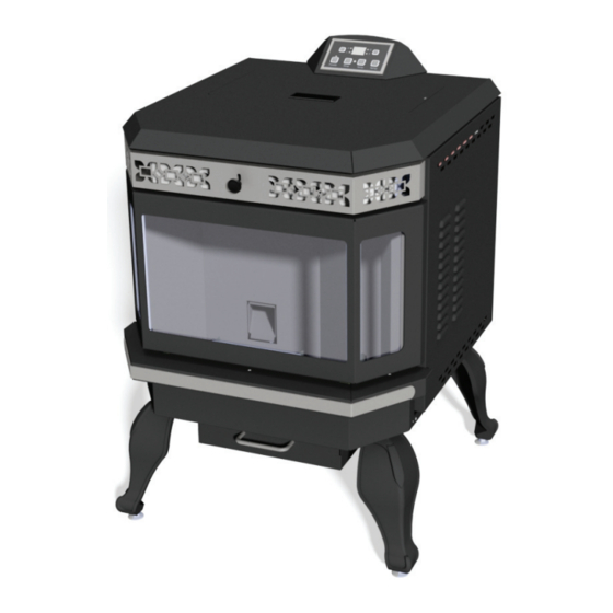
Model AP5660L
Portland
Oregon USA
This unit is not intended to be used as a primary source of heat.
SAFETY NOTICE
Save These Instructions
1
Part No.: 852072E
Advertisement
Table of Contents

Related Manuals for Ashley AP5660L


Summary of Contents for Ashley AP5660L
- Page 1 Installation and Operating Manual Model AP5660L Tested & Portland Listed by Oregon USA OMNI- Test Laboratories, Inc. Report #: 215-S-32-4 This unit is not intended to be used as a primary source of heat. SAFETY NOTICE Please read this entire manual before installation and use of this pellet fuel-burning room heater. Failure to follow instructions may result in property damage, bodily injury, or even death.
-
Page 2: Table Of Contents
TABLE OF CONTENTS Topic Page(s) Introduction ..............................3 Safety Information ............................4 Specifi cations ............................... 6 Operating Instructions ..........................7-8 Thermostat Installation ..........................9 Clearances to Combustibles ........................10 Installing Your Room Heater ........................11-18 Mobile Home Installations ..........................19 Vent Termination Locations ........................21 Maintenance ............................22-25 Troubleshooting .............................26-27 Wiring Diagram ............................28 Replacement Parts List ..........................29 Warranty Card .............................31... -
Page 3: Introduction
Introduction The entire family of United States Stove Company thanks you for purchasing your new pellet burning room heater. At U.S. Stove, we build all of our products with a hands-on approach to detail and quality. Our old world team of Craftsmen take great pride in their superior workmanship to ensure you have years of trouble free use of your pellet heater. -
Page 4: Safety Information
SAFETY INFORMATION Be sure to read the entire owner’s manual prior to installing and operating this Pellet heater. Failure to follow these instructions could result in fi re, property damage, bodily injury or even death. This stove’s exhaust system works with negative combustion chamber pressure and a slight positive chimney pressure, it is ex- tremely important to ensure that the exhaust system is sealed and airtight. - Page 5 SAFETY INFORMATION - continued Keep foreign objects out of the hopper. Contact your local building offi cials to obtain a permit and information on any installation restrictions or inspection require- ments in your area. Be sure to notify your insurance company of your new U.S. Stove Pellet Burning Room Heater. Allow the Pellet Stove Room Heater to cool before performing any maintenance.
-
Page 6: Specifi Cations
SPECIFICATIONS Heating Specifi cations: Burn Rate: *43,900 btu’s per hour or 5.1 lbs. of fuel per hour Hopper Capacity: 55 lbs. *Dependent upon quality and heating value of pellet fuel. DIMENSIONS Figure 1 34.05 [865 mm] 24.41 in 27.32 in [620.0 mm] [693.9 mm] 6.00 in... -
Page 7: Assembly Instructions
Assembly Instructions STEP 1 Pull the factory installed wires out of the top of the stove. Th ere will be two wire harnesses, ash shown. STEP 2 Unpack the top mount controls and ensure that the wiring harness shown is attached securely. STEP 3 Connect the factory installed wiring harnesses to the control panel as shown. - Page 8 Control Panel PANEL CONTROLS The blowers and automatic fuel supply are controlled from a panel on the top of the 5660. The control panel functions are a follows. ON/OFF SWITCH (“POWER” BUTTON) • When pushed, the stove will automatically ignite. No other fi re starter is necessary. The igniter will stay on for at least 10 and up to 12 minutes, depending on when Proof of Fire is reached.
-
Page 9: Proper Fuel
Operation DO NOT USE CHEMICALS OR FLUIDS TO START THE FIRE - NEVER USE GASOLINE, GASOLINE-TYPE LANTERN FUEL, KEROSENE, CHARCOAL LIGHTER FLUID, OR SIMILAR LIQUIDS TO START OR “FRESHEN UP” A FIRE IN THIS STOVE. KEEP ALL SUCH LIQUIDS WELL AWAY FROM THE STOVE WHILE IT IS IN USE. ... -
Page 10: Opening Door
Operation As a general rule, on lower feed rate settings, the damper should be farther to the left closing it off. On higher feed rates, the damper should be open more by having it set more towards the right. Through trial and error, you will fi nd the best setting. Consult your dealer if you need help. -
Page 11: Clearances To Combustibles
CLEARANCES TO COMBUSTIBLES INSTALL ALL VENTS AT CLEARANCES SPECIFIED BY THE VENT MANUFACTURER! When your Pellet Stove Room Heater is being installed on a combustible fl oor it is mandatory that a 1/2” (13mm) thick non- combustible hearth pad be installed under the heater. The non-combustible hearth pad must extend at least 6” beyond the fuel loading and ash removal openings and at least the depth of the heater plus 6 inches (152mm) out in front of the heater. -
Page 12: Installing Your Room Heater
INSTALLING YOUR ROOM HEATER You have already made the important decision of choosing your U.S. Stove Pellet Burning Room Heater; now your next step is to determine where to install your new pellet stove heater. To get the most effi cient use of re-circulated heat, you should consider a room that is centrally located within your home. - Page 13 INSTALLING YOUR ROOM HEATER - continued HORIZONTAL EXHAUST VENT INSTALLATION Figure 8 Listed Horizontal Cap Exhaust Vent Combustion Air Intake with approved cap Wall Thimble Mfg. by Pellet Vent Mfg. 6” (152mm) Clearance to Combustibles Floor Protector 6” (152mm) Clearance Front Figure 9 6”...
- Page 14 INSTALLING YOUR ROOM HEATER - continued FREESTANDING INTERIOR VERTICAL INSTALLATION 1. Locate your Pellet Stove Room Heater in a location which meets the requirements of this manual, but in an area where it does not interfere with the house framing, wiring, etc. 2.
- Page 15 INSTALLING YOUR ROOM HEATER - continued FREESTANDING EXTERIOR VERTICAL INSTALLATION 1. Locate your Pellet Stove Room Heater in a location which meets the requirements of this manual, but in an area where it does not interfere with the house framing, wiring, etc. 2.
- Page 16 INSTALLING YOUR ROOM HEATER - continued SELKIRK DIRECT-TEMP VENT SYSTEM FOR PELLET STOVE HEATERS Images courtesy of Selkirk...
- Page 17 INSTALLING YOUR ROOM HEATER- continued SELKIRK DIRECT-TEMP VENT SYSTEM FOR PELLET STOVE HEATERS Images courtesy of Selkirk UP AND OUT HORIZONTAL TERMINATION KIT FIGURE 12...
- Page 18 INSTALLING YOUR ROOM HEATER- continued SELKIRK DIRECT-TEMP VENT SYSTEM FOR PELLET STOVE HEATERS Images courtesy of Selkirk STRAIGHT OUT HORIZONTAL TERMINATION KIT FIGURE 12...
- Page 19 INSTALLING YOUR ROOM HEATER - continued SELKIRK DIRECT-TEMP VENT SYSTEM FOR PELLET STOVE HEATERS Images courtesy of Selkirk THROUGH THE ROOF VERTICAL TERMINATION KIT FIGURE 14...
-
Page 20: Mobile Home Installations
MOBILE HOME INSTALLATION Mobile home installation should be done in accordance with the Manufactured Home and Safety Standard (HUD), CFR 3280, Part 24. Canadian installations require that the heater must be connected to a 3 or 4 inch, factory-built chimney conforming to CAN/ULC-S629. -
Page 21: Vent Termination Locations
VENT TERMINATION LOCATIONS Figure 22... -
Page 22: Maintenance
MAINTENANCE FAILURE TO CLEAN AND MAINTAIN THIS UNIT AS INDICATED MAY RESULT IN POOR PERFORMANCE AND HAZARDOUS SITUATIONS. CLEAN THE HEATER FREQUENTLY AS ACCUMULATION OF SOOT, CREOSOTE OR FLYASH MAY OCCUR. NEVER CLEAN THE UNIT WHEN HOT. Burn Pot: Note: Let the unit cool to room temperature before inspecting the burn pot. Inspect the burn pot regularly to check that the holes have not become plugged. - Page 23 MAINTENANCE - continued Ash Removal - Freestanding Unit: Remove the ashes periodically to avoid unnecessary ash build up. Ash removal is as follows: 1. Let fi re burn out and allow unit cool to room temperature 2. Clean the heat exchanger tubes (see Heat Exchanger Cleaning section) – Make sure Pellet Stove is at room temperature before touching 3.
- Page 24 MAINTENANCE - continued Cleaning Heat Exchanger Tubes – Your Pellet Stove Room Heater is designed with a built in heat exchanger tube cleaner. This should be used every 2 or 3 days to remove ash build up on the heat exchanger tubes, which can reduce heat transfer. The handle, for the heat exchanger tube cleaner, is located in front of the vent tubes on front side of heater.
- Page 25 MAINTENANCE - continued Chimney/Vent System Cleaning: 1. Soot/Creosote Formation – When wood products are burned slowly, they produce tar and other organic vapors which combine with expelled moisture to form soot. The soot vapors condense in the relatively cool chimney fl ue, as a result, soot/creosote residue accumulates on the chimney lining.
-
Page 26: Troubleshooting
TROUBLE SHOOTING See replacement parts section for component locations. The heater will not light. • Check that the heater is plugged in and that the wall outlet has power. • Unplug the unit then check all electrical connections against the Wiring Diagram in this manual. •... - Page 27 TROUBLE SHOOTING - continued The 200 F High-limit switch has tripped. • Reset the switch and determine the cause. It is normally a faulty circulation fan. If the circulation fan does not operate, apply 120 volts directly to the circulation fan. If it still does not operate, replace the circulation fan. Heater will not shut off.
-
Page 28: Wiring Diagram
WIRING DIAGRAM... -
Page 29: Replacement Parts
REPLACEMENT PARTS Contact your authorized U.S. Stove Pellet Burning Room Heater dealer to obtain any of these parts. Never use substitute materials. Use of non-approved parts can result in poor performance, safety hazards, and will void your Warranty. Key Parts No. Description Qty. -
Page 30: How To Order Repair Parts
HOW TO ORDER REPAIR PARTS THIS MANUAL WILL HELP YOU OBTAIN EFFICIENT, DEPENDABLE SERVICE FROM YOUR KING OR ASHLEY, AND ENABLE YOU TO ORDER REPAIR PARTS CORRECTLY. KEEP THIS MANUAL IN A SAFE PLACE FOR FUTURE REFERENCE. WHEN WRITING, ALWAYS GIVE THE FULL MODEL NUMBER WHICH IS ON THE NAMEPLATE ATTACHED TO THE HEATER. - Page 31 WARRANTY INFORMATION CARD Name__________________________________________ Telephone #: (_____)_____________ City____________________________________________ State_______ Zip_________________ Email Address __________________________________________________________________ Model # of Unit________________________________ Serial #___________________________ Fuel Type: Wood Coal Pellet Gas Other _________________________ Place of Purchase (Retailer)______________________________________________________ City____________________________________________ State_______ Zip_________________ If internet purchase, please list website address___________________________________ Date of Purchase _______________________________________________________________ Alternative Heat Main Heat Source...
- Page 32 Fold Here Fold Here Fold Here PLACE STAMP HERE United States Stove Company P.O. Box 151 South Pittsburg, TN 37380...
Need help?
Do you have a question about the AP5660L and is the answer not in the manual?
Questions and answers
E1 codde? I don't know what it means. e 1. codde. what is. reas