Table of Contents
Advertisement
Quick Links
Advertisement
Table of Contents

Related Manuals for Diamond Systems Poseidon


Summary of Contents for Diamond Systems Poseidon
- Page 1 Poseidon User Manual EPIC format VIA CPU Board with Integrated Data Acquisition 7463010 v1.2 © Copyright 2007 1255 Terra Bella Ave. Mountain View, CA 94043 Tel (650) 810-2500 Fax (650) 810-2525 www.diamondsystems.com Diamond Systems Corporation Poseidon User Manual Page 1...
-
Page 2: Table Of Contents
PCI VI/O Voltage Setting (JP1)................35 DAQ Configuration (JP2)..................37 COM3/COM4/ADC IRQ Configuration (JP3)............38 Analog I/O Single-ended/Differential Configuration (JP4)........39 DAC Configuration (JP5)..................40 Battery Connection (JP6)..................41 ATX Power Control (JP7)..................42 RS-422/RS-485 Termination Configuration (JP8)...........43 DIO Pull-up/Pull-down Configuration (JP9)............. 43 Diamond Systems Corporation Poseidon User Manual Page 2... -
Page 3: Poseidon User Manual Page
Wait for the Conversion to Finish................81 Read the Data from the Board.................81 Convert the numerical data to a meaningful value..........82 A/D Sampling Methods....................83 Sampling Modes......................83 FIFO Description......................84 Scan Sampling......................84 Sequential Sampling....................84 How To Perform Conversions Using Interrupts............85 Diamond Systems Corporation Poseidon User Manual Page 3... -
Page 4: Poseidon User Manual Page
Watchdog Timer Programming..................98 FlashDisk Module......................100 Installing the FlashDisk Module................100 Using the FlashDisk with Another IDE Drive............101 Power Supply......................101 FlashDisk Programmer Board..................102 I/O Cables........................103 Mounting PC/104-Plus Cards onto a Poseidon Baseboard........104 Customization Options....................105 Diamond Systems Corporation Poseidon User Manual Page 4... -
Page 5: Poseidon User Manual Page
PNL-PSD Panel I/O Board for Poseidon CPU............106 Specifications......................1 15 CPU........................115 Data Acquisition Circuitry..................115 Power Supply......................116 General........................116 Additional Information....................117 Appendix A. COM3/4/ADC IRQ Configuration for First Release Boards, Rev A1 ............................118 Technical Support......................1 19 Figures Figure 1: Poseidon Functional Block Diagram..............9 Figure 2: Poseidon Board Layout..................13... -
Page 6: Poseidon User Manual Page
Figure 22: ATX Configuration Using JP7.................42 Figure 23: RS-422/RS-485 Termination Configuration Options........43 Figure 24: DIO Pull-up/Pull-down Configuration............. 43 Figure 25: Data Acquisition Block Diagram..............50 Figure 26: FlashDisk Module..................100 Figure 27: FlashDisk Programmer Board Layout............102 Diamond Systems Corporation Poseidon User Manual Page 6... -
Page 7: Introduction
PCB). Poseidon uses the PCI bus internally to connect the Ethernet circuit to the processor. It uses the ISA bus internally to connect serial ports 3 and 4, as well as the data acquisition circuit, to the processor. Both the ISA and PCI buses are brought out to expansion connectors for the connection of add-on boards. -
Page 8: Analog Output
ATX power switching capability. • Programmable watchdog timer. • I/O panel board that connects to on-board I/O brought to pin headers, to provide PC-style connectors. • Power supply: 5VDC operation from the PC-104 bus. • Diamond Systems Corporation Poseidon User Manual Page 8... -
Page 9: Block Diagram
Block Diagram Figure 1 shows the Poseidon functional blocks. Figure 1: Poseidon Functional Block Diagram Diamond Systems Corporation Poseidon User Manual Page 9... -
Page 10: Functional Overview
Functional Overview This section describes the major Poseidon subsystems. Processor Two processor options are available for the Poseidon board. Low-power, fanless 1.0GHz VIA Eden ULV CPU • High-performance 2.0GHz VIA C7 CPU • North Bridge and South Bridge The North and South bridge are integrated in the on-board VIA CX700 chip. -
Page 11: Data Acquisition
PC-104 bus and not from the on-board converter. The power supply includes ATX power switching and ACPI power management support. The master +5V input is controlled by the ATX function with an external switch input. Diamond Systems Corporation Poseidon User Manual Page 11... - Page 12 A connector and jumper are provided to disable the on-board battery and enable the use of an external battery, instead. Watchdog Timer A watchdog timer (WDT) circuit consists of a programmable timer. Diamond Systems Corporation Poseidon User Manual Page 12...
-
Page 13: Board Description
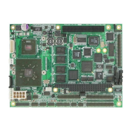
Board Description Board Layout Figure 2 shows the Poseidon board layout, including connectors, jumper blocks and mounting holes. Figure 2: Poseidon Board Layout Diamond Systems Corporation Poseidon User Manual Page 13... -
Page 14: Connector Summary
Connector Summary The following table lists the connectors on the Poseidon board. Connector Description Manufacturer Part No. LCD panel (LVDS interface) JST: BM30B-SRDS-G-TF Primary IDE Standard 2x22, 0.1” header PC/104-Plus PCI bus connector EPT 264-60303-02 LCD backlight TYCO 640456-3 Serial ATA... -
Page 15: Connectors
Connectors This section describes the on-board Poseidon connectors. PC/104 ISA Bus Connectors CN6 and CN7 carry the ISA bus signals. Figure 3 shows the PC/104 A and B pin layout for CN6, and the C and D pin layout for CN7. -
Page 16: Pc/104-Plus Pci Bus
GND/3.3V KEY On the Poseidon, all of the PCI circuitry is driven with 3.3V circuitry and is 5V tolerant. The main board can support either 3.3V or 5V-only cards. For this reason, the connector is not keyed (to prevent certain types of cards from being inserted). -
Page 17: Ps2 Mouse And Keyboard Connector
Utility Connector Connector CN18 is a 2/4-pin header for access to the standard button/LED connections. Speaker PW LED ATX power button Ground Ground Reset key The following table describes the CN18 connector pinouts. Diamond Systems Corporation Poseidon User Manual Page 17... - Page 18 Ground Reset key Connection between Reset key and ground generate a reset condition. The board remains in a reset state (with non-standby power rails disabled) until Reset key is removed from ground. Diamond Systems Corporation Poseidon User Manual Page 18...
-
Page 19: Data Acquisition (Digital I/O) Connector
Data Acquisition (Digital I/O) Connector Poseidon includes a 2x17-pin header, CN12, for all digital data acquisition I/O. DIO A7 DIO A6 DIO A5 DIO A4 DIO A3 DIO A2 DIO A1 DIO A0 DIO B7 DIO B6 DIO B5 DIO B4... -
Page 20: Data Acquisition (Analog I/O) Connector
(and other on-board ground/0V references). Do not assume that these grounds are floating. Do not apply a high-voltage input (relative to the power input ground) to these ground signals or to any other board I/O pin. Diamond Systems Corporation Poseidon User Manual Page 20... -
Page 21: Ethernet Connector
Audio ground Ground The Poseidon sound chip is AC97-compatible. The “Line Out” is powered and used for the amplified Speaker Connector output, J13, described below. The line-level output listed above is listed as either “Headphone Out” or “Line Out 2” in most of the software and documentation for this sound interface. -
Page 22: Speaker Connector
As such, each speaker should be wired directly to the appropriate pair of connections for that speaker. Do not connect the speaker low sides (-) to ground • Do not short the speaker low connections together. • Diamond Systems Corporation Poseidon User Manual Page 22... -
Page 23: External Auxiliary Power Connector (Output)
External Auxiliary Power Connector (Output) Connector CN10 provides switched power for use with external drives. If ATX is enabled, the power is switched ON and OFF with the ATX input switch. If ATX is not enabled, the power is switched ON and OFF in conjunction with the external power. Figure 5: CN10 Connector +5v (switched) Ground Ground +12v (switched) Signal Definition This is provided by the on‐board power supply, derived from the input power. It is switched off when the board is powered down. +12v This is provided by the 12V input pin on the main power connector. It is switched off when the board is powered down. Ground These are 0V ground references for the power output voltage rails, above. Cable no. 698006 mates with J15. This cable provides a standard full‐size power connector for a hard drive or CD‐ ROM drive and a standard miniature power connector for a floppy drive. Diamond Systems Corporation Poseidon User Manual Page 23 ... -
Page 24: Ide Connector
Connector CN2 is a 2x22-pin header used for the IDE connection. Reset - Ground Ground Key (not used) Ground IDEIOW- Ground IDEIOR- Ground IORDY Ground DACK- Ground IRQ15 Pulled low for 16-bit operation Not used CS1- CS3- LED- Ground Ground Not used Diamond Systems Corporation Poseidon User Manual Page 24... -
Page 25: Serial Port I/O Connector
COM1: DCD1 DSR1 RXD1 RTS1 TXD1 CTS1 DTR1 COM2: DCD2 DSR2 RXD2 RTS2 TXD2 CTS2 DTR2 COM3: DCD3 DSR3 RXD3 RTS3 TXD3 CTS3 DTR3 COM4: DCD4 DSR4 RXD4 RTS4 TXD4 CTS4 DTR4 Diamond Systems Corporation Poseidon User Manual Page 25... - Page 26 34 TXD/RXD-4 36 NC 38 NC 40 NC Signal Definition DE-9 Pin Direction TXD/RXD+n Differential Transceiver Data (HIGH) pin 2 bi-directional TXD/RXD-n Differential Transceiver Data (LOW) pin 7 bi-directional Ground (not connected) Diamond Systems Corporation Poseidon User Manual Page 26...
-
Page 27: External Battery Connector
38 NC GND 39 40 NC Signal Definition DE‐9 Pin Direction TXD+n/TXD‐n Differential transmit data ‐ Output RXD+n/RXD‐n Differential receive data ‐ Input Ground ‐ ‐ (not connected) ‐ ‐ External Battery Connector Connector CN8 is used to connect an external battery. The battery voltage for this input should be 3‐3.5V. The current draw averages under 4µA at 3V. Figure 6: CN8 Connector Battery input (+) Ground In addition to the external battery connected to CN8, the on‐board battery and an additional external battery input on Utility Connector CN18 are other possible sources for maintaining the Real‐Time Clock and the CMOS settings (BIOS settings for various system configurations). The battery that has the highest voltage will see the majority of the current draw, which is minimal. Note that there must be a battery voltage input for the default power‐up mode. Diamond Systems Corporation Poseidon User Manual Page 27... -
Page 28: Lcd Panel (Lvds Interface) Connector
LCD2 Data 3-0 +/- Secondary Data Channel, bits 3-0 (LVDS Differential signaling) LCD2 Clock +/- Secondary Data Channel, Clock (LVDS Differential signaling) +3.3V Switched Power Supply for LCD display (only powered up when LCD display is active) Ground Power Ground, 0V Diamond Systems Corporation Poseidon User Manual Page 28... -
Page 29: Vga Connector
Digital serial I/O signals used for monitor detection (DDC1 specification) HSYNC Horizontal sync VSYNC Vertical sync Note: While the DDC serial detection pins are present, a 5V power supply is not provided (the old “Monitor ID” pins are also not used). Diamond Systems Corporation Poseidon User Manual Page 29... -
Page 30: Lcd Backlight Connector
The +12V supply is removed when the system is powered down. Power Input Connector The standard Poseidon input power is supplied through the CN9 connector from an external mid-range supply. Figure 9: CN9 Connector PS_ON... -
Page 31: Usb 2.0 Connectors
LCD backlight. If these devices are not used, the “+12V” input may be left unconnected. Make certain that your power supply has enough current capacity to drive your system. The Poseidon requires 12 to 20 Watts or more, depending on which external devices are connected to the board. This could require over 4A on the “+Vin”... -
Page 32: Serial Ata Connector
Serial ATA Connector Connector CN5 is the serial ATA connector. Figure 10: Serial ATA Connector Ground Ground Ground Ground Ground Signal Definition TX+/TX- Differential outputs to PHY RX+/RX- Differential inputs from PHY Ground Ground Diamond Systems Corporation Poseidon User Manual Page 32... -
Page 33: I/O Panel Power
Power Supply ON. Feedback pin for external ATX supply, when needed; pulled low when on-board power is inactive. Ground Ground Note: Optionally, a PC/104 power supply may be used to power the board through the PC/104 bus. Diamond Systems Corporation Poseidon User Manual Page 33... -
Page 34: Standard Jtag Configuration Interface (Factory Use)
Test data input CTMS Test mode select Reference Voltage Test Point (Factory Use) Connector J2 is the reference voltage test point for use during factory calibration. +Vref Signal Definition +Vref Reference voltage Ground Diamond Systems Corporation Poseidon User Manual Page 34... -
Page 35: Board Configuration
Pin 5 The table summarizes the configuration for each option. JP7 refers to the ATX jumper on Poseidon while JP1 refers to the external power enable jumper on the panel board. To locate this jumper see the PNL-PSD panel board description in the final section of this manual. -
Page 36: Pci Vi/O Voltage Setting (Jp1)
5-PCI VIO to select +5v The Poseidon can support either I/O voltage range (all on-board signals are driven from 3.3V power rails, but are 5V tolerant), so the determination of the I/O voltage is entirely dependent on the types of PC/104-Plus cards plugged into the system. -
Page 37: Figure 12: Jp1 Settings
Note that this voltage selection is not used for standard PC/104 cards; only the PCI-signaling of PC/104-Plus. Figure 12 shows how to select the desired voltage using jumper JP1. Figure 12: JP1 Settings Diamond Systems Corporation Poseidon User Manual Page 37... -
Page 38: Daq Configuration (Jp2)
CPU. The lowest address of this address block is called the base address. The Poseidon base address is set using JP2 pins 9-14, as shown below. The table lists the possible jumper configurations, using pins 9-14, and corresponding base addresses. -
Page 39: Com3/Com4/Adc Irq Configuration (Jp3)
1,000 to 20,000 depending on the CPU and operating system. However, Poseidon contains a 1024-sample FIFO for A/D data that allows the interrupt rate to be much slower than the sample rate. The board can support full-speed sampling at up to 250,000 samples per second without the use of DMA. -
Page 40: Analog I/O Single-Ended/Differential Configuration (Jp4)
Figure 16: IRQ Selection Example Analog I/O Single-ended/Differential Configuration (JP4) The input channels on Poseidon can be configured as 32 single-ended, 16 differential, or 16 single-ended plus 8 differential. Four different configurations are possible for the Data Acquisition (Analog I/O) connector, CN13. -
Page 41: Dac Configuration (Jp5)
DAC Configuration (JP5) The analog outputs on Poseidon can be set to operate in bipolar (both + and –) or unipolar (+ only) output voltage ranges. In addition, the full-scale output range can be set to 5V, 10V, or programmable. The maximum output current on any channel is 5mA. -
Page 42: Battery Connection (Jp6)
Battery Connection (JP6) The CMOS RAM may be cleared using the 3-pin JP6 jumper block. By default, there are jumpers on pins one and two for standard BIOS configuration. Figure 21: JP6 Jumper Diamond Systems Corporation Poseidon User Manual Page 42... -
Page 43: Atx Power Control (Jp7)
Figure 18 shows the ATX configuration options using the JP7 jumper block. (Pin 3 is not connected). Figure 22: ATX Configuration Using JP7 The default configuration is ATX bypass. Diamond Systems Corporation Poseidon User Manual Page 43... -
Page 44: Rs-422/Rs-485 Termination Configuration (Jp8)
RS-422/RS-485 Termination Configuration (JP8) If the Poseidon board is the last card in a RS-422/RS-485 link, the link must be terminated. Use jumper block JP9 to terminate RS-422 and RS-485 lines for COM3 and COM4. Figure 21 shows the termination configuration options. -
Page 45: System Features
A serial port on another PC can be connected to the serial port on Poseidon with a null modem cable, and a terminal emulation program, such as HyperTerminal, can be used to establish the connection. The terminal program must be capable of transmitting special characters including F2 (some programs or configurations trap special characters). -
Page 46: Flash Memory
4. Exit the BIOS and save your settings. Flash Memory Poseidon contains a 2Mbyte, 16-bit wide flash memory chip for storage of BIOS and other system configuration data. Backup Battery Poseidon contains an integrated RTC/CMOS RAM backup battery. This battery has a capacity of 120mAH and will last over three years in power-off state. -
Page 47: System Reset
200 msec. On-Board Video Using the the on-board VIA CX700 processor, Poseidon integrates all of the support needed for modern media. Refer to the VIA Technologies, Inc. documentation for CX700-series processors, listed in the Additional Information section of this document. -
Page 48: System I/O
6-pin header Serial Ports Poseidon contains four serial ports. Each port is capable of transmitting at speeds up to 115.2Kbaud. Ports COM1 and COM2 are built into the standard chipset., which are standard 16550 UARTs with 16-byte FIFOs. Ports COM3 and COM4 are derived from an Exar 16C2850 dual UART chip and include 128-byte FIFOs. These ports may be operated at speeds to 1.5Mbaud with installation of high-speed drivers, as a custom option. -
Page 49: Ps/2 Ports
COM3 in RS-422 mode, jumper J4 pins labeled C3 422. To operate COM4 in RS-422 mode, jumper J4 pins labeled C4 422. If RS-422 mode is selected, special hardware and software consideration is required to implement RS-422. PS/2 Ports Poseidon supports two PS/2 ports. Keyboard • Mouse •... - Page 50 The USB ports can be used for keyboard and mouse at the same time that the PS/2 keyboard and mouse are connected. Diamond Systems Corporation Poseidon User Manual Page 50...
-
Page 51: Data Acquisition Circuit
If using Diamond Systems Universal Driver (DSCUD), develop code in the same way as for the DMM-32X-AT. The code developed for the DMM-32X-AT runs with no change on Poseidon, with the exception that the Poseidon DAQ does not have an equivalent to the DMM-32X-AT serial port. -
Page 52: Data Acquisition Circuitry I/O Map
Data Acquisition Circuitry I/O Map I/O Memory Space Poseidon occupies 16 bytes in the system I/O address space. Registers 12 through 15 provide paged windows for access to additional registers without requiring additional I/O address space. The following tables list the register functions and base address offset, for each page. - Page 53 Waveform Generator Control Read-back Waveform Generator Command Note: Page 6, CPLD I/O Window (Enhanced Feature Page), is a window to the CPLD I/O. This page should not be accessed in normal operation. Diamond Systems Corporation Poseidon User Manual Page 53...
-
Page 54: I/O Register Summary
PGCW0 Page 5 - D/A Waveform Generator (Enhanced Feature Page) DACA7 DACA6 DACA5 DACA4 DACA3 DACA2 DACA1 DACA0 DACA9 DACA8 DEPTH3 DEPTH2 DEPTH1 DEPTH0 WGCH1 WGCH0 WGSRC1 WGSRC0 WGINC WGRST WGPS WGSTRT Diamond Systems Corporation Poseidon User Manual Page 54... - Page 55 PICD2 PICD1 PICD0 I2CBUSY PICA4 PICA3 PICA2 PICA1 PICA0 ACHOLD PICPRST ACERR ACACT PICBSY PGDR Page 5 - D/A Waveform Generator (Enhanced Feature Page) DEPTH3 DEPTH2 DEPTH1 DEPTH0 WGCH1 WGCH0 WGSRC1 WGSRC0 Diamond Systems Corporation Poseidon User Manual Page 55...
-
Page 56: I/O Register Definitions
DOUT2 - CN12, pin 28. Counter 2 output when OUT2EN = 1 (Base+10, bit 5). DOUT1 - CN12, pin 30. DOUT0 - CN12, pin 27. Counter 0 output when OUT0EN = 1 (Base+10, bit 4). Diamond Systems Corporation Poseidon User Manual Page 56... - Page 57 Base+5), the value written to that register, along with the value written to this register, are simultaneously written to the D/A chip’s load register for the selected channel. See Base+5, write for more details. Diamond Systems Corporation Poseidon User Manual Page 57...
- Page 58 D/A wave form generator to store DAC code. 0 = Data is transferred to the DAC chip for output. DA11-8 D/A bits 11 - 8 for the selected output channel; DA11 is the MSB Diamond Systems Corporation Poseidon User Manual Page 58...
- Page 59 An overflow can be detected by checking the OVF bit in the FIFO status register at Base + 7. The correct threshold for your application can only be determined by testing. Diamond Systems Corporation Poseidon User Manual Page 59...
- Page 60 1 = FIFO has overflowed; data has been lost. This flag is cleared on the next successful A/D read. 0 = FIFO has not overflowed since the last A/D data read. FIFOEN FIFO enable read-back. SCANEN Scan enable read-back. PAGE0-1 Read-back of the current page register setting. (See Base+8 below) Diamond Systems Corporation Poseidon User Manual Page 60...
- Page 61 ADCH4-0 Current A/D channel; this is the channel currently selected on board and is the channel that will be used for the next A/D conversion (unless a new value is written to the low channel register). Diamond Systems Corporation Poseidon User Manual Page 61...
- Page 62 1, which is driven by the clock selected by bit FREQ12 in Base + 10 below. 0 = External trigger: Falling edges on the DIN3/EXTCLK pin on the I/O header generate A/D conversions. Diamond Systems Corporation Poseidon User Manual Page 62...
- Page 63 DMAEN Read-back of control register bit defined, above. Read-back of P2 register bit defined at Base+8/write. CLKEN Read-back of control register bit defined, above. CLKSEL Read-back of control register bit defined, above. Diamond Systems Corporation Poseidon User Manual Page 63...
- Page 64 (gate mode). CN12 pin 32 is connected to a 10KΩ pull-up resistor. 0 = The interrupt operation begins immediately once it is set up and the selected clock source begins, with no external triggering or gating. Diamond Systems Corporation Poseidon User Manual Page 64...
- Page 65 A/D conversions, so you can tune the board’s settings to each input signal. Note: On power up or system reset, the board is configured for A/D bipolar mode, input range = ±5V, and gain = 1, corresponding to all zeros in this register. Diamond Systems Corporation Poseidon User Manual Page 65...
- Page 66 SCINT1-0 Read-back of control bit described, above. Only available if enhanced features are enabled. RANGE Read-back of control bit described, above. ADBU Read-back of control bit described, above. G1-0 Read-back of control bit described, above. Diamond Systems Corporation Poseidon User Manual Page 66...
- Page 67 Name: CTR2D7 CTR2D6 CTR2D5 CTR2D4 CTR2D3 CTR2D2 CTR2D1 CTR2D0 CRT2D7-0 Counter 2 data. 82C54 Control: Base+15 (Read/Write) Bit: Name: SC1-0 Counter select. RW1-0 Read/write mode. M2-0 Timer mode. Binary Coded Decimal counter. Diamond Systems Corporation Poseidon User Manual Page 67...
- Page 68 0 = Output. DIRB 1 = Input. DIRCL Note: Bit 7 must be set to 1. This indicates port configure mode in the 8255 (as opposed to bit set mode, which is not supported). Diamond Systems Corporation Poseidon User Manual Page 68...
- Page 69 This is an enhanced features page. It is only accessible when enhanced features are enabled. Expanded FIFO Depth: Base+12 (Read/Write) Bit: Name: This bit is used when setting the FIFO threshold. See the documentation for register Base+6 for more information. Diamond Systems Corporation Poseidon User Manual Page 69...
- Page 70 1 enable cal mux and disable user analog input channels. 0 disable cal mux, enable user inputs. TDACEN TrimDAC Enable. Writing 1 to this bit initiates a transfer to the TrimDAC (used in the autocalibration process). Diamond Systems Corporation Poseidon User Manual Page 70...
- Page 71 Name: This register is the revision level of the FPGA design. This value changes with new versions of the FPGA. It provides a way to distinguish between different versions of FPGA code. Diamond Systems Corporation Poseidon User Manual Page 71...
- Page 72 Address Read-back: Base+13 (Read) Bit: Name: I2CBUSY PICA4 PICA3 PICA2 PICA1 PICA0 I2CBUSY I2C port status bit: 0 = Last I2C operation completed. 1 = Last I2C operation in progress. PICA4-0 dsPIC address last accessed. Diamond Systems Corporation Poseidon User Manual Page 72...
- Page 73 1 = dsPIC device present on board. ACERR 1 = dsPIC detected errors during last Auto-autocal process ACACT 1 = Auto-autocal process currently in progress.. PICBSY 1 = dsPIC busy, either with auto-autocal or some other activity. Diamond Systems Corporation Poseidon User Manual Page 73...
- Page 74 1 at a time. Bits are processed MSB to LSB. The first 1 bit determines which command is executed. dsPIC Programming Status: Base+15 (Read) Bit: Name: PGDR PGDR Reads back current level of PIC_PGD line (low = 0, high = 1). Diamond Systems Corporation Poseidon User Manual Page 74...
- Page 75 DACA7-0 LSB of address to store D/A code in D/A waveform buffer. Waveform Buffer Address (MSB): Base+13 (Write) Bit: Name: DACA9 DACA8 DACA9-8 MSB of address to store D/A code in D/A waveform buffer. Diamond Systems Corporation Poseidon User Manual Page 75...
- Page 76 Force the waveform generator to increment one frame. Note: Only one bit can be set to 1 at a time. Bits are processed MSB to LSB. The first 1 bit determines which command is executed. Diamond Systems Corporation Poseidon User Manual Page 76...
-
Page 77: Enabling Enhanced Features
Enabling Enhanced Features Poseidon has many newly added features that are only accessible when “enhanced features” is enabled. These features include D/A wave form generator (access to Page 5), larger FIFO size of 1024 (access to Page 2), dsPIC and auto autocalibration (access to Page 4), and various others. -
Page 78: Analog-To-Digital Input Ranges And Resolution
Overview Poseidon uses a 16-bit A/D converter. This means that the analog input voltage can be measured to the precision of a 16-bit binary number. The maximum value of a 16-bit binary number is 216 - 1, or 65535, so the full range of numerical values that you can get from a Poseidon analog input channel is 0 - 65535. -
Page 79: A/D Conversion Formulas
A/D Code Input Voltage Symbolic Formula Input Voltage for ± 5V Range -32768 -5.0000V -32767 + 1 LSB -4.9998V -1 LSB -0.00015V 0.0000V +1 LSB 0.00015V 32767 - 1 LSB 4.9998V Diamond Systems Corporation Poseidon User Manual Page 79... - Page 80 A/D Code Input Voltage Symbolic Formula Input Voltage for 0−10 V Range -32768 0.0000V -32767 1 LSB (V / 65536) 0.153mV / 2 - 1 LSB 4.99985V 5.0000V / 2 + 1 LSB 5.00015V 32767 - 1 LSB 9.9998V Diamond Systems Corporation Poseidon User Manual Page 80...
-
Page 81: Performing An A/D Conversion
Select the Input Channel Poseidon contains a channel counter circuit that controls which channel will be sampled on each A/D conversion command. The circuit uses two channel numbers called the low channel and high channel. These are stored in registers at Base+2 and Base+3. -
Page 82: Select The Input Range
// combine the 2 bytes into a 16-bit value Alternatively, the value can be read as one 16-bit value, which is preferred since this method increases overall system bandwidth while reading data from the FIFO. For example, Diamond Systems Corporation Poseidon User Manual Page 82... -
Page 83: Convert The Numerical Data To A Meaningful Value
A/D data back to the original input voltage. You may also convert the result into engineering units. The two conversions can be done sequentially, or the formulas can be combined into a single formula. Diamond Systems Corporation Poseidon User Manual Page 83... -
Page 84: A/D Sampling Methods
Sampling Modes There are several different A/D sampling modes available on Poseidon. The mode in use is selected with the FIFO enable and Scan enable bits at the FIFO control register at Base+7 as well as the A/D interrupt enable bit in the Interrupt control register at Base+9. -
Page 85: Fifo Description
FIFO Description Poseidon uses a 1024-sample FIFO (First In First Out) memory buffer to manage A/D conversion data. It is used to store A/D data between the time it is generated by the A/D converter and the time it is read by the user program. In enhanced mode, the entire 1024-sample FIFO is available. -
Page 86: How To Perform Conversions Using Interrupts
1. A/D channel range (low channel, high channel). On Poseidon, the channel numbers range from 0 to 31. Some channel numbers may not be available, depending on the single-ended/differential configuration mode as explained on page 11. D uring interrupt- based A/D conversions, the channels being sampled must be consecutive in number. -
Page 87: Analog Output Ranges And Resolution
Full-scale Range Selection The D/A converter chip on Poseidon requires two references, one for the low end and one for the high end of the range. The high end can be set to 5V, 10V, or Programmable, and the low end can be either 0V (for unipolar output ranges) or minus the high-end voltage. -
Page 88: Digital-To-Analog Conversion
Use the following formulas to compute the LSB and MSB values. LSB = (D/A Code) AND 255. Keep only the low 8 bits MSB = int((D/A code) / 256). Strip off low 8 bits, keep 4 high bits Diamond Systems Corporation Poseidon User Manual Page 88... -
Page 89: Add The Channel Number To The Msb
Using the bipolar mode formula, we compute D/A code = 3V / 5V * 2048 + 2048 = 3276.8. Round this up to 3277. (Binary value = 1100 1100 1101) 2. Compute LSB and MSB. LSB = 3277 & 255 = 205 (Binary value = 1100 1101) Diamond Systems Corporation Poseidon User Manual Page 89... - Page 90 //select page 3 outp(Base + 15, 0xA6); //enable enhanced features outp(Base + 4, LSB); outp(Base + 5, MSB); 6. Monitor DACBUSY bit, Base + 4 bit 7. while (inp(Base + 4) & 0x80); Diamond Systems Corporation Poseidon User Manual Page 90...
-
Page 91: Waveform Generator
DASIM to 1, set DAGEN to 1. The D/A value code must be computed for the desired voltage. From the computed value, obtain the LSB and MSB and add the Diamond Systems Corporation Poseidon User Manual Page 91... - Page 92 Page 5, Base+14, bits 4, 5, and 6. Start D/A Waveform Generator Initialize D/A waveform output by writing 1 to Page 5, Base + 15, bit 0. The generator continues to output the periodic waveform until you disable it. Diamond Systems Corporation Poseidon User Manual Page 92...
-
Page 93: Auto-Calibration
8-bit TrimDAC and precision, low-drift reference voltages on the board. The optimum TrimDAC values for each input range are stored in an EEPROM and recalled automatically on power up. Poseidon also has the A/D auto-calibration algorithm programmed into the dsPIC, featuring a fast, autonomous auto- calibration. -
Page 94: Performing Auto-Calibration With Software
DMM32CAL.EXE, is provided to enable calibration without requiring any programming. Performing Auto-calibration with dsPIC Poseidon has an onboard microprocessor that can perform auto-calibration for you, automatically. The microprocessor can be configured to trigger calibration because of temperature changes, or it can be manually triggered by software. -
Page 95: Digital I/O Operation
Digital I/O Operation Poseidon contains two sets of digital I/O lines. An internal 82C55-type digital I/O circuit provides 24 digital I/O lines that emulate the function of Mode 0 of • an 8255 chip. These lines are buffered to provide extra drive current in output mode, and are available on digital I/O header, CN12. -
Page 96: Auxiliary Digital I/O
Only Port A may be operated in Mode 1. In all cases, the starting/resting conditions are Latch input = low, and Acknowledge output = low. Note: Mode 1 is not currently supported by Diamond Systems Universal Driver software. Auxiliary Digital I/O CN12 contains three digital outputs and four digital inputs that can be used either for general purpose digital I/O, or for A/D and counter/timer functions. - Page 97 This signal may always be read at Base+,4 bit 0. It may function as an external clock for counter 0 when SRC0 = 0 in Base+10, bit 1. When used as a clock for Counter 0, the rising edge is active. Diamond Systems Corporation Poseidon User Manual Page 97...
-
Page 98: Counter/Timer Operation
Counter/Timer Operation Counter/Timer Features and Configuration Options Poseidon emulates an 82C54 counter/timer chip, providing 3 16-bit counter/timers. Counters 1 and 2 are cascaded together to form a 32-bit counter/timer for use as a programmable A/D sampling clock. The output of counter 1 provides the input for counter 2, and the output of counter 2 is fed to the A/D triggering circuit as well as the I/O header CN12. -
Page 99: Watchdog Timer Programming
WDEN1 WDEN0 WDEN7-0 Writing 0x99 to this register enables and loads the watchdog timer with the value in the Base+5 register. Writing any other value to this register disables the watchdog timer. Diamond Systems Corporation Poseidon User Manual Page 99... - Page 100 WDTRIG bit in Base+4. This reloads the counter with the value in Base+5. If the counter reaches zero, watchdog circuitry pulses the reset line and disables the watchdog timer. 3. Disable the watchdog timer at any time by writing any value other than 99h to Base+7. Diamond Systems Corporation Poseidon User Manual Page 100...
-
Page 101: Flashdisk Module
FlashDisk Module Poseidon is designed to accommodate an optional solid-state FlashDisk module. This module contains 128MB, 256MB, 512MB, 1GB, 2GB, or 4GB of solid-state non-volatile memory that operates like an IDE drive without requiring additional driver software support. Model Capacity... -
Page 102: Using The Flashdisk With Another Ide Drive
The power may be provided from the CPU’s power out connector, J12, or from one of the two 4-pin headers on the ACC-IDEEXT board. Poseidon cable no. 6981006 may be used with either power connector to bring power to the drive. -
Page 103: Flashdisk Programmer Board
The board can also be used to enable the simultaneous connection of two drives to the CPU. Connector J1 connects to the IDE connector on Poseidon with a 44-pin ribbon cable ( part no. 6981004). Both 40-pin 0.1-inch spacing, J4, and 44-pin 2mm spacing, J3, headers are provided for the external hard drive or CD-ROM drive. -
Page 104: I/O Cables
USB, 2mm to 2x USB 6981083 PS2, 2mm to 2x Mini-DIN 6981084 VGA, 2mm to DD15F 6981085 Audio, 2mm to 3x 3.5mm 6981087 Poseidon Speaker Out 6981088 Poseidon Utilities 6981091 Poseidon Power In Diamond Systems Corporation Poseidon User Manual Page 104... -
Page 105: Mounting Pc/104-Plus Cards Onto A Poseidon Baseboard
Mounting PC/104-Plus Cards onto a Poseidon Baseboard Poseidon is designed to serve as a baseboard for a stack of PC/104 or PC/104-Plus boards. Up to four PC/104-Plus boards are supported. Any PC/104 boards should be mounted on top of the PC/104-Plus board stack, when both board types are to be combined. -
Page 106: Jumper Configuration
The panel board contains two configuration jumpers JP1 and JP2. External Power Enable - JP1: Use a jumper between pins 1 and 2 only if Poseidon is to be powered from an external power supply such as PS-5V-04 via the panel board and power switch emulation is desired. - Page 107 USB ports 2 and 3 are brought out to two locations, a front panel industry-standard dual-port connector and a topside pin header. The topside pin header is a 2x5mm header that mirrors the pinout of the connector on Poseidon. 2.4 Topside Utility Header The 2x4 Poseidon utility header should be mirrored on the topside using a 2x4 2mm SMT male pin header.
- Page 108 The Panel board will interface with an internal DC/DC converted using two connectors. A 1x6 0.156” straight friction lock header will carry the variable power input (ref. Molex 26-48-1065). 1 Variable Power Input 2 Variable Power Input 3 Ground Diamond Systems Corporation Poseidon User Manual Page 108...
- Page 109 Connect to ‘PS Shut Down’ on internal headers PS_SHUT_DOWN Connect to Variable Power Input line POWER_INPUT POWER_SWITCH Connect to pin 3 of the Poseidon utility header REMOTE_ON_OFF Connect to pin 20 of the Poseidon power header Diamond Systems Corporation Poseidon User Manual...
- Page 110 CPU connectors. Ports 0 and 1 connect to the combination USB/Ethernet connector. Ports 2 and 3 go to a 2-port USB connector on the panel and a 2x5 pin header for internal use (see above). 1 Pwr + 2 Data - Diamond Systems Corporation Poseidon User Manual Page 110...
- Page 111 Only one of these inputs is used at a time. +12V may also be provided via this connector for use by an LCD backlight. 1 +5V 2 +5V 3 Gnd 4 Vin 5 +12V 6 +5V 7 Gnd 8 Gnd 9 Vin Diamond Systems Corporation Poseidon User Manual Page 111...
- Page 112 PCB will be parallel to the Poseidon PCB. The panel board may extend 1” from the lower edge of the Poseidon to support the external headers. It will extend no further than required to support the connectors along the lower edge of the Poseidon.
-
Page 113: Customization Options
Customization Options There are many customer-specific customizations that can be done for the Poseidon, including: Latching connectors (replacing the box headers used for most of the board I/O connections). • Connectors with extra gold contact plating. • Alternative heatsinks for low air-flow and dusty environments. -
Page 114: Specifications
Output current: Logic 0: 64mA max per lineLogic 1: -15mA max per line • A/D Pacer clock: 32-bit down counter (2 82C54 counters cascaded) • Clock source: 10MHz on-board clock or external signal • General purpose: 16-bit down counter (1 82C54 counter) • Diamond Systems Corporation Poseidon User Manual Page 114... -
Page 115: Power Supply
Input Voltage: +5VDC ±5% • General Dimensions: 4.528” x 6.496” (115mm x 165mm) • Weight: • PSDE10 - 512N, 8.3 oz. • PSDE10 - 512A, 8.6 oz. • PSDC20 - 1024A, 9.0 oz. • Diamond Systems Corporation Poseidon User Manual Page 115... -
Page 116: Additional Information
Additional Information Additional information can be found at the following websites. 1. Diamond Systems Corporation: http://www.diamondsystems.com/ 2. VIA Technologies, Inc. (Processors): http://www.via.com.tw/en/products/processors/ 3. VIA Technologies, Inc. (North/South bridge): http://www.via.com.tw/en/products/chipsets/c-series/cx700/ Diamond Systems Corporation Poseidon User Manual Page 116... -
Page 117: Appendix A. Com3/4/Adc Irq Configuration For First Release Boards, Rev A1
IRQ4; selectable for COM3 or ADC COM3 select for IRQ AD select for IRQ AD select for IRQ IRQ5; selectable for COM3 or ADC IRQ6; selectable for COM3 or ADC COM3 select for IRQ Diamond Systems Corporation Poseidon User Manual Page 117... -
Page 118: Technical Support
Technical Support For technical support, please email support@diamondsystems.com or contact technical support at 1-650-810-2500. Diamond Systems Corporation Poseidon User Manual Page 118...
Need help?
Do you have a question about the Poseidon and is the answer not in the manual?
Questions and answers