Advertisement
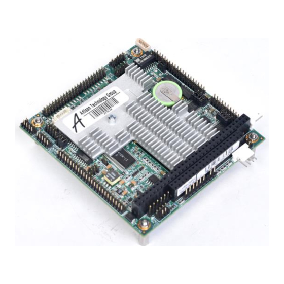
This document describes a series of quick steps to bring up and verify correct operation of your new Helios PC/104
single board computer (SBC). All the elements you need are provided in the Helios Development Kit (Diamond
Systems #DK-HLV800A-01). Once you have your Helios SBC up and running, you can make further adjustments
using additional elements that you supply.
The steps involve unpacking and identifying each part in the Helios Development Kit, attaching a minimum subset
of cables required to verify operation, and powering the board.
1. Install the IDE FlashDisk module with bootable Linux binary on primary IDE connector
J12
2. Install the VGA cable 6981084 and monitor on connector J10
3. Connect the keyboard and mouse
a. For PS/2 connections install combination cable 6981083 on connector J3 then
connect a PS/2 keyboard and mouse
b. For USB connections install USB cable 6981082 on connector J15 for USB ports
0/1 or on connector J16 for USB ports 2/3 and connect a USB keyboard and
mouse
4. Connect the AC Adapter to the power connector J4
5. Turn on the monitor and plug in the AC Adapter. The Helios board will boot to a Linux
prompt.
Helios FastStart Guide
Diamond Systems
Helios Single Board Computer
FastStart Guide
DSC Document #7461030 Rev A
Diamond Systems Corp.
(650) 810-2500
www.diamondsystems.com
Quick List of Assembly Steps
7461010 Rev A
Page 1 of 8
Advertisement
Table of Contents

Related Manuals for Diamond Systems Helios


Summary of Contents for Diamond Systems Helios
- Page 1 (650) 810-2500 www.diamondsystems.com This document describes a series of quick steps to bring up and verify correct operation of your new Helios PC/104 single board computer (SBC). All the elements you need are provided in the Helios Development Kit (Diamond Systems #DK-HLV800A-01).
- Page 2 The Helios Development Kit contains all the pieces necessary to bring up and verify correct operation of your Helios SBC. The following table lists the elements of the Helios Development Kit and each is shown in Figure 1. Please unpack and identify each item at this time. If any item is missing, please contact Diamond Systems Technical Support at 1-800-36-PC104.
- Page 3 IDC40F 2mm-DB9Mx4, 12” cable 6981163 Crimp50xIDC50FxIDC50F, 21 0.1”x2MMx2MM cable 6981006 Auxiliary power cable Dual USB cable (2 cables in kit) 6981082 6981009 Power I/O cable Figure 2. Helios Cable Kit Helios FastStart Guide 7461010 Rev A Page 3 of 8...
- Page 4 ACC-IDEEXT FlashDisk Programmer Board In the event that you wish to connect both a flashdisk and an IDE hard disk drive or CD-ROM drive to your Helios board, the Helios Development Kit comes with the ACC-IDEEXT FlashDisk Programmer Board. When connected directly to the Helios board, the flashdisk occupies the primary IDE interface connector which does not allow for a second drive to be attached to the primary IDE connector.
- Page 5 3. Attach the female IDE connector on the flashdisk to the IDE connector J12 on the Helios SBC. 4. Fasten the flashdisk in place by inserting one 2-56x pan head screw from the solder side of the Helios SBC into the round spacer.
- Page 6 Plug in the video monitor and turn it on. Attach the power cord provided to the PS-5V-04 AC Adapter and plug the power cord into the wall. The Helios SBC will power up immediately. After the BIOS information display, you should see the Diamond Systems’ Linux information display and receive a prompt.
- Page 7 +-2 are within tolerance. For more details regarding A/D modes refer to section “Input Ranges and Resolutions” in the Helios User’s Manual. For more information regarding the software API and functions please refer to the Universal Driver Software manual at http://docs.diamondsystems.com/dscud/manual_Main+Page.html.
- Page 8 Note: The 44-pin connectors (J1, J2, and J3) and mating cables carry +5V power, but the 40-pin connector (J4) and mating cable do not. J5 and J6 on the FDPB or J12 on Helios may be used to provide power to an IDE device when the device is attached to the 40-pin J4 connector on the FDPB using the Auxiliary Power Cable 6981006 provided with the Helios Development Kit.
Need help?
Do you have a question about the Helios and is the answer not in the manual?
Questions and answers