Table of Contents
Advertisement
Quick Links
AURORA Single Board Computer
TM
PC/104
Single Board Computer with Atom Z-Series CPU and SUMIT
Revision
Date
A5
1/16/2012
A6
2/24/2012
FOR TECHNICAL SUPPORT
PLEASE CONTACT:
support@diamondsystems.com
Comment
Minor updates
Added new Z510 models
TM
Expansion
Copyright 2012
Diamond Systems Corporation
555 Ellis Street
Mountain View, CA 94043 USA
Tel 1-650-810-2500
Fax 1-650-810-2525
www.diamondsystems.com
Advertisement
Table of Contents

Related Manuals for Diamond Systems Aurora


Summary of Contents for Diamond Systems Aurora
- Page 1 AURORA Single Board Computer PC/104 Single Board Computer with Atom Z-Series CPU and SUMIT Expansion Revision Date Comment 1/16/2012 Minor updates 2/24/2012 Added new Z510 models Copyright 2012 FOR TECHNICAL SUPPORT Diamond Systems Corporation PLEASE CONTACT: 555 Ellis Street Mountain View, CA 94043 USA support@diamondsystems.com...
-
Page 2: Table Of Contents
Mass Storage Devices ........................16 3.2.4 Connecting Power ..........................16 3.2.5 Display ............................... 16 3.2.6 Installing Aurora in an Enclosure (optional) ..................16 Booting the System ............................ 17 3.3.1 BIOS Setup ............................17 3.3.2 Operating System Drivers ........................17 Interface Connector Details .......................... 18 SDVO Connector (SDVO1) ........................ -
Page 3: Www.diamondsystems.com Page
PS/2 Keyboard and Mouse (J25 Keyboard, J26 Mouse) ..............41 11.2.6 Serial Ports (COM1, COM2, COM3, COM4) ..................41 11.3 Power Routing ............................42 12. Thermal Pad ..............................44 13. Specifications ..............................45 www.diamondsystems.com Page Aurora User Manual Rev A6... -
Page 4: Important Safe-Handling Information
The list here describes common causes of failure found on boards returned to Diamond Systems for repair. This information is provided as a source of advice to help you prevent damaging your Diamond (or any vendor’s) embedded computer boards. -
Page 5: Introduction
1. INTRODUCTION Aurora is a high performance, highly integrated single board computer in the PC/104 form-factor incorporating a wealth of standard PC-style I/O plus on-board digital I/O. It accepts both SUMIT-A and PC/104 (ISA) add-on I/O modules. An integrated, bottom-mounted heatspreader dissipates heat efficiently to the system enclosure. This configuration leaves the SBC’s top side free for easy access to memory, on-board I/O, and expansion sockets. -
Page 6: Aurora Sbc Features
All other trademarks are the property of their respective owners. 1.1 Aurora SBC Features Aurora is a rugged, single board computer (SBC) based on the 1.6GHz Intel Atom Z-Series CPU and conforming to the compact, PC/104 form-factor (90 x 96mm). It provides multiple expansion options by means of PC/104 (ISA) modules and SUMIT-A modules. -
Page 7: Sumit Socket Resources
SBC without the need for a fan. Four mounting holes on the bottom of the conduction cooled heatspreader are provided to mount Aurora in an enclosure or to a bulkhead. These mounting holes are #6-32 threaded holes on 2.8" centers. -
Page 8: Functional Overview
2. FUNCTIONAL OVERVIEW 2.1 Block Diagram Figure 2 shows Aurora’s functional blocks. Figure 2: Aurora Functional Block Diagram www.diamondsystems.com Page Aurora User Manual Rev A6... -
Page 9: Aurora Dimensions
2.2 Aurora Dimensions Figure 3 shows the overall dimensions of the Aurora SBC. Figure 3: Aurora Dimensions www.diamondsystems.com Page Aurora User Manual Rev A6... -
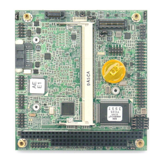
Page 10: Connector Locations
2.3 Connector Locations Figure 4 illustrates the position of interface and bus connectors jumpers located on the top side of the Aurora SBC. Two expansion buses – PC/104 (ISA) and SUMIT-A (PCIe, etc.) – enable on-board stacking of additional I/O boards. The connectors for both expansion buses are located on the top side of the board. -
Page 11: Connector Summary
The following table summarizes the functions of Aurora’s interface, utility, and power connectors. Signal functions relating to all of Aurora’s interface connectors are discussed in greater detail in Section 4 of this document. Diamond offers an optional Aurora Cable Kit (number C-AUR-KIT), which provides mating cable assemblies for most of Aurora’s I/O interface connectors. -
Page 12: Configuration Jumpers
2.4 Configuration Jumpers Figure 5 shows the configuration jumper groups that are located on the topside of the Aurora SBC. Refer to Section 5 for details on the functions and configuration options associated with each jumper group. JVLCD1 JLCD1 JBKC1 JINV1... -
Page 13: Configuration Jumper Summary
2.4.1 Configuration Jumper Summary Aurora’s configuration jumpers are listed below. Refer to Section 5 of this document for details regarding the configuration of these jumper groups. Jumper Group Function Silkscreen Label Array Size LCD Panel Power Select (3.3V/5V) JVLCD1 1 x 3... -
Page 14: Introducing The Aurora Development Kit
3.1 Introducing the Aurora Development Kit The Aurora Development Kit (DK-AUR-01) provides everything required for Aurora-based rapid application development. The table below lists the boards, cables, and other items included. Item Diamond P/N Description AUR-Z530-16-1G Aurora PC/104 SBC, 1.6GHz Atom Z530, 1GB SDRAM... -
Page 15: Aurora Cable Kit
3.1.1 Aurora Cable Kit The Aurora Cable Kit (number C-AUR-KIT) provides convenient access to most of Aurora’s I/O features. The kit’s cable assemblies are shown in the photo below, and identified in the table that follows. Note: On each interface cable, the end of the cable connector that has a red wire going to it should be oriented toward the end of the board connector that is labeled “pin 1”... -
Page 16: System Setup
If desired, connect SATA hard drives to Aurora by connecting a USB cable, part number 6981082, to connector USB1 and then to the SATA drive. Aurora can operate with a combination of SATA and CD-ROM drives, and can boot from either of them. -
Page 17: Booting The System
3.3.1 BIOS Setup Aurora’s BIOS provides a wide range of configuration options. When you power up Aurora for the first time, you should immediately enter the BIOS “Setup” utility in order to adjust BIOS settings to match your system’s peripheral devices and other requirements, and to configure various other hardware and software parameters. -
Page 18: Interface Connector Details
4. INTERFACE CONNECTOR DETAILS This section describes the functions associated with the Aurora baseboard’s SUMIT-A bus, PCI-104 bus expansion stack, utility, I/O interfaces, and power connectors in greater detail. Section 3.1.1 contains a list of ready-to-use interface cables included in Diamond’s Aurora Cable Kit. -
Page 19: Lcd Panel (Lvds Interface) Connector (Lvds1)
4.2 LCD Panel (LVDS Interface) Connector (LVDS1) This connector is mounted on the bottom side of Aurora, directly below the SDVO connector, SDVO1. It provides connection to an LVDS LCD display. The LCD panel power is jumpeRSelectable for 3.3V (default) or 5V. -
Page 20: Sumit-A Expansion Bus (Sumita1)
4.4 SUMIT-A Expansion Bus (SUMITA1) The SUMIT-A stackable bus is a 52-pin surface mount connector located on the expansion side of the board. Aurora implements the following SUMIT bus functions: 1 PCIe x1 lane 3 USB 2.0 channels LPC bus... -
Page 21: Serial Ports (Com1, Com2)
Ports 1 and 2 are fixed for RS-232 only, while ports 3 and 4 may be jumper-configured for RS-232, RS-422, or RS-485 protocols. The connector pinout changes depending on the selected protocol. Aurora can be custom- ordered preconfigured for a selected protocol; it is also possible to order a fixed configuration with soldered-on zero ohm resistors, so no jumpers are used. -
Page 22: Ps/2 Keyboard/Mouse (Kbms1)
Mating connector and pin types: A2005H02 2x5P connector with A2005T0P-00 terminals 4.7 External Battery (BAT1) Aurora has provision for an external battery connection via BAT1, a two-pin connector. A connector and jumper are provided to disable the on-board battery and enable use of an external battery instead. -
Page 23: Pc/104 (Isa) Expansion Bus (Pc104_1)
SA16 DACK3- SD11 DACK7- SA15 DRQ3 SD12 DRQ7 SA14 DACK1- SD13 SA13 DRQ1 SD14 MASTER- SA12 REFRESH- SD15 Ground SA11 SYSCLK Ground SA10 IRQ7 IRQ6 IRQ5 IRQ4 IRQ3 DACK2- BALE Ground Ground Ground www.diamondsystems.com Page Aurora User Manual Rev A6... -
Page 24: Input Power (Pwr1)
4.10 Ethernet (LAN1) This connector provides access to the board's gigabit Ethernet port. Common Connector type: Standard 2mm dual row vertical pin header with 4mm posts and gold flash plating Mating connector: Molex 51110-1050 connector www.diamondsystems.com Page Aurora User Manual Rev A6... -
Page 25: Usb 0-1 (Usb1)
USB2 Data- USB3 Pwr+ USB2 Pwr+ Connector type: Standard 2mm dual row vertical pin header with 4mm posts and gold flash plating Mating connector and pin types: Molex 51110-1050 connector with Molex 50394-8100 terminals www.diamondsystems.com Page Aurora User Manual Rev A6... -
Page 26: Usb Flashdisk (Usb3)
A standard SO-DIMM DDR2 DRAM connector is provided for system memory. 4.15 SATA (SATA1) The SATA connector is an industry-standard connector. Ground Transmit+ Transmit- Ground Receive- Receive+ Ground Connector type: Industry-standard horizontal SATA connector, SATA 7P female with lock www.diamondsystems.com Page Aurora User Manual Rev A6... -
Page 27: Gpio (Gpio_P1)
Connector type: Standard 2mm dual row vertical pin header with 4mm posts and gold flash plating Mating connector and pin types: A2005H02 2x5P connector with A2005T0B-00 terminals 5. CONFIGURATION JUMPER DETAILS This section explains the use of several jumper options on the Aurora Baseboard. Jumper Group Function Silkscreen Label Array Size LCD Panel Power Select (3.3V/5V) -
Page 28: Lcd Backlight Brightness Control (Jbkc1)
Forward Scan Direction (default) 5.5 CMOS RAM Reset / On-board Backup Battery Disconnect (JBAT1) This jumper group controls the external battery backup enable settings. Setting Mode Backup battery Short 1-2 connected (default) Short 2-3 Clear CMOS www.diamondsystems.com Page Aurora User Manual Rev A6... -
Page 29: Serial Ports (Jcom3, Jcom4)
5.6 Serial Ports (JCOM3, JCOM4) Following is the Aurora multi-protocol jumper selection for COM3 and COM4. Port COM3 is associated with jumper block JCOM3, and COM4 is associated with JCOM4. www.diamondsystems.com Page Aurora User Manual Rev A6... -
Page 30: Bios
6. BIOS Aurora’s BIOS provides access to many valuable features. These instructions show how to enter the BIOS, set up features, and restore the BIOS to its default settings. 6.1 Entering the BIOS The BIOS may be entered during startup by pressing the DEL key on an attached keyboard or pressing F4 if using console redirection. -
Page 31: Super I/O Configuration
115200 (default when enabled), 57600, 38400, 19200 and 9600. When set to Enabled, the BIOS can be accessed by pressing F4 on the remote keyboard. BBS POPUP can be accessed by pressing F3 on that remote keyboard. www.diamondsystems.com Page Aurora User Manual Rev A6... -
Page 32: Digital I/O Lines
7. DIGITAL I/O LINES Aurora has eight digital I/O lines found on connector GPIO_P1. This connector has one pin for each line plus an External Reset Input and Ground line. Please note that the digital I/O lines on Aurora are not 5V tolerant. - Page 33 ( i=0; i<=3500; i++ ) dscInp ( 0x6C, &m_OutBuf ); if ( ( m_OutBuf&0x00000001) > 0 ) temp=Read_io_port(0x68); temp= (temp & 0x000000FF ) ; return temp; break; if ( i > 3499 ) temp=Read_io_port(0x68); return 0xFFFFFFFF; //---------------------------------------------------------------------------- www.diamondsystems.com Page Aurora User Manual Rev A6...
- Page 34 ECRamAddrH ); if ( uDATA==0xFFFFFFFF ) { return 0xFFFFFFFF;} uDATA=Process_686C_Command_Write(0x000000A2, ECRamAddrL ); if ( uDATA==0xFFFFFFFF ) { return 0xFFFFFFFF;} uDATA=Process_686C_Command_Write(0x000000A5, ECUMemData ); if ( uDATA==0xFFFFFFFF ) { return 0xFFFFFFFF;} return 0x00000000; //---------------------------------------------------------------------------- www.diamondsystems.com Page Aurora User Manual Rev A6...
-
Page 35: Watchdog Timer
WDT_CNT[7:0] Read: the current count of the watchdog timer Write: the same value to enable the timer 0 to disable the timer Power-on default [7:0] = 0x0Ah when DTR3#/PS_WDT is pulled-up, else 0x00h. www.diamondsystems.com Page Aurora User Manual Rev A6... -
Page 36: Programming Sample Code
8.2 Programming Sample Code Following is sample code for programming Aurora’s watchdog timer. The base address for the watchdog timer is 0x300. Fintek F81216D Watchdog Timer sample code */ /*----- Include Header Area -----*/ #include "math.h" #include "stdio.h" #include "dos.h"... -
Page 37: Flashdisk Modules
9. FLASHDISK MODULES 9.1 Overview Aurora is designed to accommodate an optional wide-temperature solid-state USB flashdisk module for rugged mass storage in place of a notebook hard drive or commercial flashdisk. This module contains 1GB to 8GB of solid-state non-volatile memory that operates like any USB hard disk drive without requiring additional driver software support. -
Page 38: Flashdisk Installation
Aurora comes with ruggedized RSODIMM™ SO-DIMM SDRAM modules for improved performance in high shock and vibration environments. These modules securely affix to the Aurora single board computer through a pair of standoffs and screws. This innovative design ensures that the SO-DIMM module remains fixed in place and cannot back out of its socket. -
Page 39: Panel I/O Board
Ethernet PS/2 Keyboard & mouse The panel I/O board may be used together with the Aurora SBC in an “open frame” configuration, or the assembly can be installed in a Pandora enclosure to create a complete, cable-free, compact industrial computer. -
Page 40: Mechanical Drawing
JMM OUT (J2), JMM IN (J6), JMM IN (J5), REG5V (J3), and 12V/VIN (J4), from left to right looking from the top. Figure 6: Aurora Panel I/O Board Connectors www.diamondsystems.com... -
Page 41: Outside Facing I/O Connectors
DC/DC power supply is then fed either to the PC/104 bus power pins (if the power supply is on the PC/104 bus) or back to the panel board and then to the Aurora SBC through the +5V pins on the SBC mating power input connector. -
Page 42: Power Routing
0.156” friction lock connector for a front panel switch and then to the same pin socket on the bottom side that mates with Aurora. In this case the switch would be DPDT type instead of the SPDT type used by 5V or 12V only. - Page 43 Figure 7: Power Routing Schematic www.diamondsystems.com Page Aurora User Manual Rev A6...
-
Page 44: Thermal Pad
12. THERMAL PAD A thermal pad is included with every Aurora. It is the same size as the heatspreader and attaches to the bottom of the heatspreader, but is shipped loose with the product. Customers can choose to affix the thermal pad or not depending on their needs. -
Page 45: Specifications
Expansion buses: SUMIT-A stackable, PC/104 (ISA) stackable Input power: 5V ±5% Power consumption: 5.4W Operating temperature : -40°C to +80°C (-40°F to +176°F) at headspreader surface MTBF: 211,720 hours (Aurora Z530 models) Shock: MIL-STD-202G Table 213-1 J Half-Sine Wave Shock...
Need help?
Do you have a question about the Aurora and is the answer not in the manual?
Questions and answers