Table of Contents
Advertisement
Quick Links
This document describes a series of quick steps to bring up and verify correct operation of your new Hercules II
EBX Single Board Computer. All the elements you will need to complete this assembly are provided in the
Hercules II Development Kit (Diamond Systems #DK-HRC-02). Once you have your Hercules II board up and
running, you can make further adjustments using additional elements that you supply.
The set of steps involve unpacking and identifying each part in the Hercules II Development Kit, attaching a
minimum subset of cables required to verify operation, and powering the board.
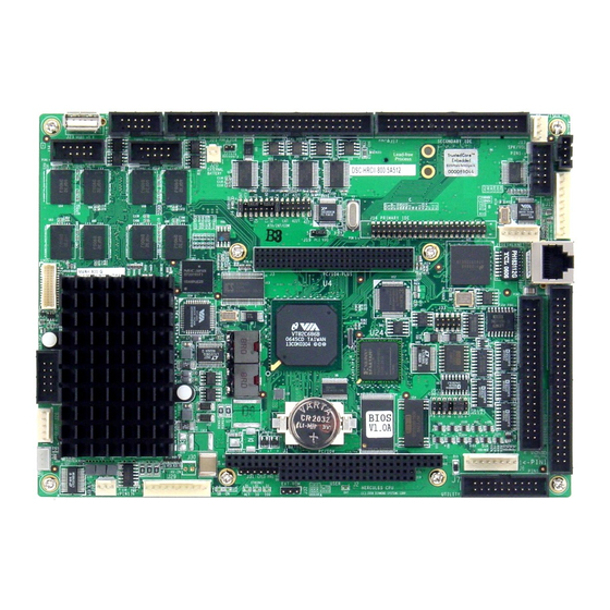
1. Install the IDE FlashDisk Drive with bootable Linux binary on primary IDE connector J16
2. Install the Utility Board (#8611002) on connector J7
3. Install the VGA cable (#6981024) and monitor on connector J25
4. Install either the PS/2 keyboard / mouse cable (#6981022) on connector J6 or one USB
cable (#6081012) on connector J21 or J22 and the keyboard / mouse
5. Connect the AC Adapter to the power connector J29
6. Turn on the monitor and plug in the AC Adapter. The Hercules II board will boot to a
Linux prompt.
Hercules II Fast Start Guide
Diamond Systems
Hercules II Single Board Computer
FastStart Guide
DSC Document #7460001 Rev A
Diamond Systems Corp.
(650) 810-2500
www.diamondsystems.com
Quick List of Assembly Steps
DSC #7460001A,
Page 1 of 8
Advertisement
Table of Contents

Related Manuals for Diamond Systems Hercules II


Summary of Contents for Diamond Systems Hercules II
- Page 1 (650) 810-2500 www.diamondsystems.com This document describes a series of quick steps to bring up and verify correct operation of your new Hercules II EBX Single Board Computer. All the elements you will need to complete this assembly are provided in the Hercules II Development Kit (Diamond Systems #DK-HRC-02).
- Page 2 The Hercules II EBX Development Kit The Hercules II Development Kit contains all the pieces necessary to bring up and verify correct operation of your Hercules II EBX Single Board Computer. The following table lists the elements of the Hercules II Development Kit.
- Page 3 External (3V) Battery power cable 4-wire output power cable for external drives 6981006 6981012 Dual USB cable 8611002 Utility Board (used instead of C-20-18 for development) Figure 2. Hercules II Cable Kit Hercules II Fast Start Guide DSC #7460001A, Page 3 of 8...
- Page 4 Linux utilizes the Minix file system for enhanced file protection during power loss or improper shutdown, and the Lilo bootloader for a quick 15 second boot time. The Hercules II Development Kit also includes a CD which provides a binary image of the FlashDisk files that you may copy freely for use on Hercules II CPUs.
- Page 5 3. Attach the female IDE connector on the FlashDisk to the IDE connector J16 on the Hercules II board. 4. Fasten the FlashDisk in place by inserting one 2-56x pan head screw from the solder side of the Hercules II board into the round spacer.
- Page 6 For the USB interface, connect one of the two USB cables (DSC#6981012) provided in the Hercules II Cable Kit to one of the two USB connectors (either J21 or J22) on the Hercules II board. Connect a USB keyboard to one of the Type A USB connectors at the other end of the USB cable.
- Page 7 IDE device. You can power the device by using the Auxiliary Power Cable (DSC #6981006) provided in the Hercules II Cable Kit connected to the External Power Connector (J15) on the Hercules II Board. You may configure the device as either master or slave. You may need to make changes to the BIOS setup to access this device.
- Page 8 Note: The 44-pin connectors (J1, J2, and J3) and mating cables carry power, but the 40-pin connector (J4) and mating cable do not. J5 and J6 on the FDPB or J15 on the Hercules II may be used to provide power to an IDE device when the device is attached to the 40-pin J4 connector on the FDPB using the Auxiliary Power Cable (DSC#6981006) provided with the Hercules II Cable Kit.
Need help?
Do you have a question about the Hercules II and is the answer not in the manual?
Questions and answers