Table of Contents
Advertisement
Quick Links
Download this manual
See also:
User Manual
HELIX SINGLE BOARD COMPUTER
Revision
Date
A
12/15/2011
FOR TECHNICAL SUPPORT
PLEASE CONTACT:
support@diamondsystems.com
PC/104 SBC with Vortex Processor
and Dual 10/100 Ethernet Switch
Rev A: December 2011
Comment
Released version
Copyright 2011
Diamond Systems Corporation
555 Ellis Street
Mountain View, CA 94043 USA
Tel 1-650-810-2500
Fax 1-650-810-2525
www.diamondsystems.com
Advertisement
Table of Contents

Related Manuals for Diamond Systems HELIX SINGLE BOARD COMPUTER


Summary of Contents for Diamond Systems HELIX SINGLE BOARD COMPUTER
- Page 1 HELIX SINGLE BOARD COMPUTER PC/104 SBC with Vortex Processor and Dual 10/100 Ethernet Switch Rev A: December 2011 Revision Date Comment 12/15/2011 Released version Copyright 2011 FOR TECHNICAL SUPPORT Diamond Systems Corporation PLEASE CONTACT: 555 Ellis Street Mountain View, CA 94043 USA support@diamondsystems.com...
-
Page 2: Table Of Contents
CONTENTS Important Safe Handling Information ......................4 Introduction ...............................6 Functional Block Diagram ..........................8 Board Diagram ..............................9 Connector and Jumper Lists ........................10 I/O Connectors ............................10 Configuration Jumpers ..........................10 I/O Connectors ............................... 11 Multi-Power Input (J4) ..........................11 +5V Power (J33) ............................11 Wide Voltage Input Power (J32) ......................... -
Page 3: Www.diamondsystems.com Page
16.2 IDE Flashdisk Models and Capacities ......................38 16.3 Configuration and Installation ........................38 16.4 BIOS FlashDisk Configuration ........................39 16.5 Using the FlashDisk with Another IDE Drive ....................39 17. Mass Storage Accessories ........................... 40 17.1 ACC-IDEEXT FlashDisk Programmer Board ..................... 40 17.2 ACC-CFEXT CompactFlash Adapter ...................... -
Page 4: Important Safe Handling Information
This creates many opportunities for accidental damage during handling, installation and connection to other equipment. The list here describes common causes of failure found on boards returned to Diamond Systems for repair. This information is provided as a source of advice to help you prevent damaging your Diamond (or any vendor‟s) embedded computer boards. - Page 5 Overvoltage on analog input – If a voltage applied to an analog input exceeds the design specification of the board, the input multiplexor and/or parts behind it can be damaged. Most of our boards will withstand an erroneous connection of up to 35V on the analog inputs, even when the board is powered off, but not all boards, and not in all conditions.
-
Page 6: Introduction
2. INTRODUCTION Helix is an embedded single board computer in the PC/104 small form factor based on the DMP Vortex86DX family of all-in-one 486 processors. Helix integrates a complete embedded PC plus an additional dual 10/100Bast-T Ethernet switch, and DC/DC power supply, into a single board. The board includes the following key system features: Processor and Memory 800MHz Vortex86DX CPU with integrated North Bridge/South Bridge, 10/100 Ethernet MAC/PHY, quad... - Page 7 Battery Backup Helix contains a backup battery for the real-time clock and BIOS settings. The battery is directly soldered to the board and provides a minimum 7 year backup lifetime at 25°C. For longer lifetime an external battery of 3.3V +/- 10% may be attached to the board.
-
Page 8: Functional Block Diagram
3. FUNCTIONAL BLOCK DIAGRAM Functional Block Diagram www.diamondsystems.com Helix User Manual Rev A Page 8... -
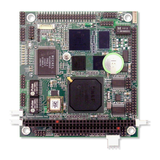
Page 9: Board Diagram
4. BOARD DIAGRAM The diagram below shows the board layout, including connectors, jumper blocks and mounting holes. Board Layout www.diamondsystems.com Helix User Manual Rev A Page 9... -
Page 10: Connector And Jumper Lists
5. CONNECTOR AND JUMPER LISTS 5.1 I/O Connectors Connector Function PC/104, ISA bus 8-bit connector (rows A, B) PC/104, ISA bus 16-bit connector (rows C, D) PS/2 keyboard/mouse Auxiliary power input I/O power External battery Digital I/O Serial ports COM1-4 LCD backlight J11, J30, J31 Ethernet... -
Page 11: I/O Connectors
6. I/O CONNECTORS Note: Pins marked as “key” are cut away or removed. 6.1 Multi-Power Input (J4) Input power may be supplied using either the input power connector J4, the I/O power connector J5, fixed +5V input J33, wide voltage input J32, or directly through the PC/104 bus power pins, if a PC/104 power supply is used with the SBC. -
Page 12: I/O Power (J5)
Connector J5 provides an alternate connector for either input power to the system or output power for use with external drives. This connector mates with Diamond Systems cable number 6981006, which provides a standard full-size power connector for a hard drive or CD-ROM drive and a standard miniature power connector for a floppy drive. -
Page 13: Serial Ports (J8)
6.5 Serial Ports (J8) Connector J8 provides access to the four serial ports of the Vortex CPU. The PORT1 and PORT2 ports are, independently, jumper-configurable for either RS-232, RS-485 or RS-422 protocol. Jumpers J25 and J26 are used to select the protocol. The PORT3 and PORT4 ports are fixed RS-232 protocol. All four serial ports can be independently enabled or disabled in the BIOS. -
Page 14: Ps/2 Mouse And Keyboard (J3)
USB ports 2/3. USB 2.0 provides a 480Mbps maximum data transfer rate. The shield pin on each connector is tied to system ground. Diamond Systems‟ cable number 6981082 mates with these connectors. J15, USB ports 0 and 1... -
Page 15: Ethernet (J11, J30, J31)
6.8 Ethernet (J11, J30, J31) The 10/100 Base-T, full-duplex Ethernet interface is provided by connectors J11, J30 and J31. J11 provides the Ethernet port signals driven from the Vortex CPU. J30 and J31 are the two Ethernet ports from the Micrel switch. All three connectors have the same pinout as shown below. -
Page 16: Lvds Lcd Interface (J13, Bottom Side Of Board)
6.10 LVDS LCD Interface (J13, bottom side of board) Connector J13 is used to connect an LVDS LCD. The LCD panel power is jumper-selectable for 3.3V (default) or 5V via jumper J18. Helix does not support TTL LCDs. If needed, the LCD backlight can be connected to connector J9. Ground / D3+, depending on video chip Ground / D3-, depending on video chip Scan Direction (High = Reverse Scan, Low/open = Normal Scan) -
Page 17: Ide (J12)
The IDE connector is a standard notebook hard drive type 2x22 (44-pin) 2mm-pitch pin header. It mates with Diamond Systems‟ cable number 6981004, and may be used to connect up to 2 IDE drives (hard disks, CD- ROMs, or flashdisk modules). An IDE flashdisk may also be installed on this connector to provide rugged, wide temperature solid state storage up to 4GB. -
Page 18: Digital I/O (J7)
6.14 Digital I/O (J7) Connector J7 provides 16 digital I/O lines from the Vortex CPU. These lines are buffered and have ESD protection to protect the SBC from potential damage. The buffers enable the direction to be programmed in 8-bit groups, using two additional GPIO lines from the Vortex processor. -
Page 19: Pc/104 Isa Bus (J1, J2)
6.16 PC/104 ISA Bus (J1, J2) The PC/104 bus is essentially identical to the ISA Bus except for the physical design. It specifies two pin and socket connectors for the bus signals. A 64-pin header J1 incorporates the 62-pin 8-bit bus connector signals, and a 40-pin header J2 incorporates the 36-pin 16-bit bus connector signals. -
Page 20: Configuration Jumpers
7. CONFIGURATION JUMPERS Helix contains the following configuration jumper blocks. The diagram on page 9 shows the location on the board of the jumper blocks. Jumper Description LCD backlight COM1 RS-422/RS-485 configuration COM2 RS-422/RS-485 configuration 7.1 LCD Backlight Power (J18) Jumper block J18 configures the voltage supply for the LCD backlight. -
Page 21: Rs-422/Rs-485 Configuration (J25, J26)
7.2 RS-422/RS-485 Configuration (J25, J26) Use J25 to select the COM1 RS-422/RS-485 termination and J26 to select the COM2 RS-422/RS-485 termination. Any port configured for RS-232 should not have any jumpers installed. COM3 and COM4 are fixed RS-232, so no termination configuration is available for them. Although the diagrams below show labels on the jumper blocks, there are no labels on the board. -
Page 22: System Resources
8. SYSTEM RESOURCES The table below lists the default system resources utilized by the circuits on Helix. Device I/O Address ISA IRQ ISA DMA 0x3F8 – 0x3FF – Serial Port COM1 0x2F8 – 0x2FF – Serial Port COM2 0x3E8 – 0x3EF –... -
Page 23: Video Features
Helix includes a video subsystem that provides both CRT and LCD output with several choices of resolution. The resolution is fixed in the BIOS but can be changed with a software utility provided on the Diamond Systems CD. LCD Resolution... -
Page 24: Lcd
9.2 LCD There are two common types of LCD signaling used in embedded computers: LVDS and TTL. The LCD output on Helix uses the more popular LVDS (low-voltage differential signaling) format. If you are planning to use a TTL LCD with Helix, you will need to use a small adapter board that converts LVDS to TTL. Many such boards are available from suppliers. -
Page 25: Changing The Lcd / Crt Resolution
The enable signal on J9 controls power to the backlight. It is controlled by Helix GPIO signal Port 3 Bit 6. The LCD display can also be enabled or disabled by using GPIO signal Port 3 Bit 5. To control these settings in software, do the following: 1. -
Page 26: Modifying The Bios With A New Lcd Resolution
9.3.1 Modifying the BIOS with a New LCD Resolution The BIOS image is modified by using a Windows XP utility called MMTOOL.EXE that can be run on any Windows XP computer. You will need the following items to modify the BIOS image: 1. -
Page 27: Updating The Bios With Spiflash Software
5. Click on the “Replace” tab. 6. Click on the “Browse” button and select the BIOS extension file that has the desired LCD resolution, then click “Open” to accept the file and close the dialog box. The BIOS extension files are listed below. Note that the BIOS extension files have an extension of .bin instead of .rom. -
Page 28: Installation And Configuration
The following are a few example boot scenarios. Install an IDE flashdisk directly on the IDE connector J12. Connect a laptop IDE hard drive directly to J12 through a 44-pin ribbon cable such as Diamond Systems cable 6981004. Use cable 6981004 to connect an IDE flashdisk programmer board to J12. You can then install a flashdisk on the programmer board and connect another 40-pin or 44-pin IDE compatible device to the programmer board. -
Page 29: Bios Functions
11. BIOS FUNCTIONS The BIOS on Helix provides access to many valuable features. These instructions show how to enter the BIOS, set up features, and restore the BIOS to its default settings. 11.1 Entering the BIOS The BIOS may be entered during startup by pressing the DEL key on an attached keyboard or pressing F4 if using console redirection. -
Page 30: Blue Led
11.6 Blue LED Helix contains a programmable blue LED along the top edge of the board, near the VGA connector. This LED is controlled by the Vortex processor GPIO port 3 bit 4. It can be turned on and off in the BIOS and in software. The LED is on by default. -
Page 31: Dual Ethernet Switch
12. DUAL ETHERNET SWITCH 12.1 Overview The 2-port Micrel Ethernet switch is a proven, fourth generation, integrated, fully managed Layer 2 switch that is entirely compliant to IEEE802.3u standards. The switch can be configured as a low-latency repeater to allow for „cut thru‟... -
Page 32: Serial Ports And System Console
13. SERIAL PORTS AND SYSTEM CONSOLE 13.1 Overview Helix contains four 16550-style asynchronous serial ports derived from the Vortex86 processor. Each port has 16- character transmit and receive FIFOs and is capable of transmitting at speeds of 9600, 19.2K, 38.4K, 57.6K, or 115.2Kbaud. -
Page 33: Console Redirection To A Serial Port
13.3 Console Redirection to a Serial Port In many applications without a local display and keyboard, it may be necessary to obtain occasional keyboard and monitor access to the CPU for configuration, file transfer, or other operations. Helix supports this activity by enabling keyboard input and character output onto a serial port, referred to as console redirection. -
Page 34: Digital I/O Ports
14. DIGITAL I/O PORTS Vortex Processor Digital I/O Ports The Vortex processor has an integrated digital I/O (GPIO) circuit with 5 8-bit ports. Two of them (ports 0 and 1) are available for use as general purpose digital I/O on Helix and are identified as ports D and E. These ports are accessible on I/O connector J7. - Page 35 Direction Control Register The GPIO port 2 direction register at address 0x9A should always be set for all output mode by writing 0xFF to it. This is the default setting, so no change should be required. Then the DIO port D/E direction control data can be written to bits 1 and 0 of address 0x7A.
-
Page 36: Watchdog Timer
15. WATCHDOG TIMER The watchdog timer can be used to trigger an interrupt or system reset upon the expiration of a programmed time interval. The purpose of this timer is to enable the system to recover from a software or hardware error that causes the system to freeze or get caught up in a software infinite loop. - Page 37 0x69 Write WDT Timeout Event Bit No. Name WDTEV3 WDTEV2 WDTEV1 WDTEV0 WDTEV3-0 Selects the event to occur upon timeout: Binary Signal / Function 0000 Invalid setting 0001 IRQ3 0010 IRQ4 0011 IRQ5 0100 IRQ6 0101 IRQ7 0110 IRQ9 0111 IRQ10 1000 Invalid setting...
-
Page 38: Flashdisk Module
16. FLASHDISK MODULE 16.1 Overview Helix is designed to accommodate an optional wide-temperature solid-state IDE flashdisk module for rugged mass storage in place of a notebook hard drive or commercial flashdisk. This module contains 128MB to 4GB of solid-state non-volatile memory that operates like an IDE drive without requiring additional driver software support. -
Page 39: Bios Flashdisk Configuration
The power may be provided from the SBC‟s power out connector, J5, or from one of the two 4-pin headers on the ACC-IDEEXT board. Diamond Systems‟ cable number 6981006 may be used with either power connector to bring power to the drive. -
Page 40: Mass Storage Accessories
17. MASS STORAGE ACCESSORIES 17.1 ACC-IDEEXT FlashDisk Programmer Board The FlashDisk Programmer Board, model number ACC-IDEEXT, may be used to connect both a flashdisk module and a standard IDE hard drive or CD-ROM drive to the Helix SBC to allow file transfers to/from the flashdisk during system setup. -
Page 41: Acc-Cfext Compactflash Adapter
17.2 ACC-CFEXT CompactFlash Adapter The CompactFlash adapter, model number ACC-CFEXT, enables the use of a CompactFlash device for mass storage on the Helix SBC. It includes a 44-wire cable, part number 6981004. This cable connects from the IDE connector on Helix to the 44-pin connector on the adapter. Both IDE signals and +5V are provided to the board via the 44-wire cable. -
Page 42: I/O Cables
18. I/O CABLES Diamond Systems offers Cable Kit C-HLX-KIT with cables for all I/O connectors on the board except the LCD and backlight. Some cables are also available separately. Helix Cable Kit: C-HLX-KIT Photo No. Cable Part No. Description Helix Connector... -
Page 43: Specifications
19. SPECIFICATIONS CPU Circuit Processor Vortex86DX Speed 800MHz Cooling Heat sink System bus 100MHz SDRAM memory 256MB 533MHz DDR2, soldered Display type 18-bit single-channel LVDS LCD CRT resolution 1600 x 1200 max LCD resolution 1600 x 1200 max Video memory 128MB USB ports 4 USB 2.0...
Need help?
Do you have a question about the HELIX SINGLE BOARD COMPUTER and is the answer not in the manual?
Questions and answers