Table of Contents
Advertisement
Quick Links
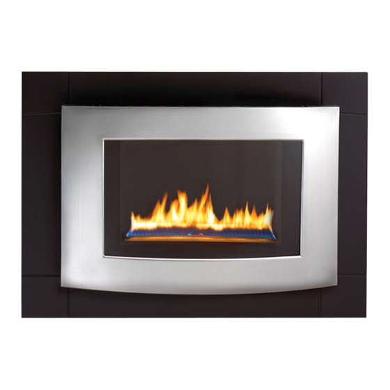
WALL MOUNT FIREPLACE
MODEL: RD-C
WARNING: IF THE INFORMATION IN THIS MANUAL IS NOT FOLLOWED
EXACTLY, A FIRE MAY RESULT CAUSING PROPERTY DAMAGE, PERSONAL
INJURY, OR LOSS OF LIFE.
– Do not store or use gasoline or other flammable vapors and liquids in vicinity of
this or any other appliance.
WHAT TO DO IF YOU SMELL GAS
· Do not try to light any appliance.
· Do not touch any electrical switch; do not use any phone in your building.
· Immediately call your gas supplier from a neighbor's phone. Follow the gas
supplier's instructions.
· If you cannot reach your gas supplier, call the fire department.
– Installation and service must be performed by a qualified installer, service
agency or the gas supplier.
This is an unvented gas-fired heater. It uses air (oxygen) from the room in which it is
installed. Provisions for adequate combustion and ventilation air must be provided.
Refer to Air For Combustion and Ventilation section on page 5 of this manual.
INSTALLER: DO NO DISCARD THIS MANUAL – LEAVE FOR HOMEOWNER'S
FUTURE REFERENCE
This appliance may be installed in an aftermarket*, permanently located
manufactured (mobile) home, where not prohibited by local codes. This appliance is
only for use with the type of gas indicated on the rating plate. this appliance is not
convertible for use with other gases.
Questions about installation, operation, or troubleshooting? Before returning to your retailer,
call customer service department toll-free at (877)886-5989.
CAUTION – FOR YOUR SAFETY
WARNING: This appliance is equipped
for (Natural and Propane) gas. Field
conversion is not permitted other than
between natural or propane gases.
PC-RD621-0707
Advertisement
Table of Contents

Related Manuals for Procom RD-C


Summary of Contents for Procom RD-C
- Page 1 WALL MOUNT FIREPLACE MODEL: RD-C CAUTION – FOR YOUR SAFETY WARNING: IF THE INFORMATION IN THIS MANUAL IS NOT FOLLOWED EXACTLY, A FIRE MAY RESULT CAUSING PROPERTY DAMAGE, PERSONAL INJURY, OR LOSS OF LIFE.
-
Page 2: Table Of Contents
BEFORE USING THIS APPLIANCE IMPORTANT: Read instructions and warnings carefully before starting installation. Failure to follow these instructions may result in a possible fire hazard and will void the warranty. PRODUCT SPECIFICATIONS RD-C ITEM NO Input Rating 20000 BTU/Hr 20000 BTU/Hr... -
Page 3: Important Safety Information
IMPORTANT SAFETY INFORMATION IMPORTANT: Read this owner’s manual carefully and completely before trying to assemble, operate, or service this heater. Improper use of this heater can cause serious injury or death from burns, fire, explosion, electrical shock, and carbon monoxide poisoning. Installation and service must be performed by a qualified installer, service agency, or local gas supplier. -
Page 4: Qualified Installing Agency
This heater needs fresh air ventilation to run properly. This heater has an Oxygen Depletion Sensing (ODS) safety shutoff system. The ODS shuts down the heater if not enough fresh air is available. See Air for Combustion and Ventilation, pages 5 through 7. If heater keeps shutting off, see Troubleshooting, pages 15 through 17. Do not run heater: ·... -
Page 5: Air For Combustion And Ventilation
UNPACKING Remove top inner pack Tilt carton so that fireplace is upright. Remove protective side packaging. Slide fireplace out of carton. Remove protective plastic wrap. Check for any shipping damage. If fireplace is damaged, promptly inform dealer where you bought fireplace. WATER VAPOR: A BY-PRODUCT OF UNVENTED ROOM HEATERS Water vapor is a by-product of gas combustion. - Page 6 Unusually tight construction is defined as construction where: walls and ceilings exposed to the outside atmosphere have a continuous water vapor retarder with a rating of one perm (6x10 kg per pa-sec-m ) or less with openings gasketed or sealed b) weather stripping has been added on windows that can be opened and doors c) caulking or sealants are applied to areas such as joints around window and door frames, between sole plates and floors, between wall-ceiling joints, between wall panels, at penetrations for plumbing, electrical, and gas lines, and at other...
-
Page 7: Installation
Ventilation Air From Inside Building This fresh air would come from adjoining unconfined space. When ventilating to an adjoining unconfined space, you must provide two permanent openings: one within 12 inches of the wall connecting the two spaces (see options 1 and 2, Figure 1). -
Page 8: Clearances To Combustibles
CLEARANCES TO COMBUSTIBLES Carefully follow the instructions below. This fireplace is a wall mount unit designed to mount directly on a wall. IMPORTANT: You must maintain minimum wall and ceiling clearances during installation. The minimum clearances are shown in Figure 3. Measure from outermost point of fireplace. Minimum Wall and Ceiling Clearances (see Figure 3) A. - Page 9 INSTALLATION Continued CAUTION: Use only new black iron or steel pipe. Internally tinned copper tubing may be used in certain areas. Check your local codes. Use pipe of ½ inch diameter or greater to allow proper volume gas to heater. If pipe is too small, loss of pressure will occur.
- Page 10 Figure 7 Figure 8 Figure 9 CHECKING GAS CONNECTIONS WARNING: Test all gas piping and connections for leaks after installing or servicing. Correct all leaks immediately. Pressure Testing Gas Supply Piping System Test Pressures In Excess Of 1/2 PSIG (3.5kPa) Disconnect heater with its appliance main gas valve (control valve) and equipment shutoff valve from gas supply piping system.
- Page 11 Pressure Testing Heater Gas Connections Open equipment shutoff valve (see Figure 10). Open gas supply tank valve. Make sure control knob of heater is in the OFF position. Check all joints from equipment shutoff valve to control valve (Figure 11). Apply mixture of liquid soap and water to gas joints. Bubbles forming show a leak Correct all leaks immediately.
- Page 12 INSTALLATION Continued Marking Screw Locations: Tape mounting bracket to wall where heater will be located. Make sure mounting bracket is level. WARNING: Maintain minimum clearances shown in Figure 13. If you can, provide greater clearances from floor and joining wall. Mark screw locations on wall (see Figure 13).
-
Page 13: Operating
OPERATING FOR YOUR SAFETY READ BEFORE LIGHTING WARNING: If you do not follow these instructions exactly, a fire or explosion may result causing property damage, personal injury or loss of life. When lighting the pilot, follow these instructions exactly. BEFORE LIGHTING smell all around the appliance area for gas. Be sure to smell next to the floor because some gas is heavier than air and will settle on the floor. -
Page 14: Inspecting Burner
OPERATING Continued Note: If pilot goes out, repeat steps 3 through 8. This heater has a safety interlock system. Wait one (1) minute before lighting pilot again. Turn control knob counterclockwise to desired heating level. The main burner should light. Set control knob to any heat level between 1 and 5. -
Page 15: Cleaning & Maintenance
CLEANING AND MAINTENANCE WARNING: Turn off heater and let cool before servicing. CAUTION: You must keep control areas, burner, and circulating air passageways of heater clean. Inspect these areas of heater before each use. Have heater inspected yearly by a qualified service technician. Heater may need more frequent cleaning due to excessive lint from carpeting, bedding material, pet hair, etc. - Page 16 TROUBLESHOOTING Continued OBSERVED PROBLEM PROBABLE CAUSE REMEDY When ignitor button is pressed in, Ignitor is positioned wrong. Replace ignitor. there is no spark at ODS/pilot Ignitor electrode is broken. Replace electrode. Ignitor electrode is not connected to Reconnect ignitor cable. ignitor cable.
- Page 17 TROUBLESHOOTING Continued OBSERVED PROBLEM PROBABLE CAUSE REMEDY Burner backfiring during combustion. Burner orifice is clogged or damaged. 1. Clean burner orifice (see Cleaning and Maintenance page 15) replace. Burner is damaged. 2. Contact Dealer or Customer Service. Gas regulator is damaged. 3.
-
Page 18: Replacement Parts
REPLACEMENT PARTS NOTE: Use only original replacement parts. This will protect your warranty coverage for parts replaced under warranty. PARTS UNDER WARRANTY Contact authorized dealers of this product. If they can’t supply original replacement parts, call Customer Service toll free at (1-877-886-5989) for referral information. -
Page 19: Parts List
PARTS LIST RD-C This list contains replaceable parts used in your heater. When ordering parts, follow the instructions listed under Replacement Parts on page 18 of this manual. KEY NO PART NUMBER DESCRIPTION QUANTITY RV83F1(L)(S) REGULATOR W20DT023 ODS OUTLET TUBE 1... - Page 20 PARTS LIST RD-C This list contains replaceable parts used in your heater. When ordering parts, follow the instructions listed under Replacement Parts on 18 of this manual. KEY NO PART NUMBER DESCRIPTION QUANTITY W20DT402-1 LEFT/RIGHT DECORATIVE PANEL W20DT120 FRONT PANEL ASSEMBLY...