Table of Contents
Advertisement
Quick Links
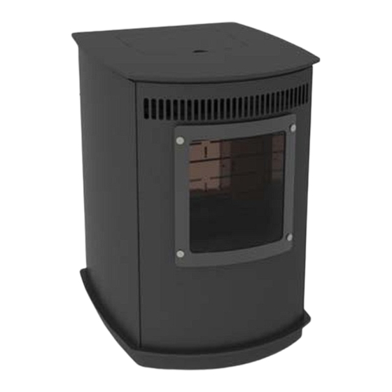
INSTALLATION AND OPERATION MANUAL
Hearthland Itasca
Pellet Stove
VS0952_E
PELLET STOVE
Hearthland Hiawatha
Pellet Stove
SAFETY NOTICE
PLEASE READ THIS ENTIRE MANUAL BEFORE INSTALLATION AND USE OF
THIS PELLET FUEL-BURNING ROOM HEATER. FAILURE TO FOLLOW THESE
INSTRUCTIONS COULD RESULT IN PROPERTY DAMAGE, BODILY INJURY
CONTACT LOCAL BUILDING OR FIRE OFFICIALS ABOUT RESTRICTIONS
AND INSTALLATION INSPECTION REQUIREMENTS IN YOUR AREA.
•
Hot! Do not touch! The glass and surfaces of this ap-
pliance will be hot during operation and will retain
heat for a while after shutting off the appliance. Se-
vere burns may result!
•
Hearthland pellet burning appliances are designed for
use as a supplemental heater. They are not intended
for continuous use as a primary heat source.
12/30/2009
Hearthland Nokomis
OR EVEN DEATH.
SAVE THESE INSTRUCTIONS.
WARNINGS
Pellet Stove
Advertisement
Table of Contents

Summary of Contents for Hearthland Itasca
-
Page 1: Safety Notice
Se- vere burns may result! • Hearthland pellet burning appliances are designed for use as a supplemental heater. They are not intended for continuous use as a primary heat source. ... - Page 2 COPYRIGHT NOTICE Copyright 2009, Hearthland Products LLC All rights reserved. No part of this manual may be copied, transmitted, transcribed, stored in a retrieval system, in any form or by any means without the expressed written permission of...
-
Page 3: Table Of Contents
C ABLE ONTENTS 1 G I 4.12 S M O 28 ENERAL NFORMATION ETTING PERATION 1.1 I S I 4 4.13 T M ( ) 29 MPORTANT AFETY TEMS HERMOSTAT ODES OPTIONAL 1.2 S L 5 5 W P S ... -
Page 4: Important Safety Items
• Stoves are dangerously hot. Young children should be supervised when they are in the same room as the stove. • The Hearthland is designed and approved for pelletized wood fuel only. Any other type of fuel burned in this stove will void the warranty and safety listing. Keep foreign objects out of the hopper. • NEVER use gasoline, gasoline‐type lantern fuel, kerosene, charcoal lighter fluid, or similar liquids to start or ’freshen up’ a fire in this heater. Keep all such liquids well away from the heater while it is in use. • The Hearthland is designed to use a standard 115 Volt 3‐prong grounded electrical outlet. A grounded surge protector is strongly recommended to prevent damage to your stove in the event of lightning or other power surge instances. Never use an adapter plug or sever the grounding prong on the electrical plug. Never route the electrical cord underneath, in front of, over the stove or over the exhaust piping. If you suspect a malfunction push the “OFF” Touch Pad and inspect the stove. Note: The Hearthland Stove will not operate during a power outage unless attached to a correctly sized generator or battery backup. If a power outage occurs, open a window to vent any smoke from room. If the malfunction persists unplug the unit and call your authorized dealer. Never operate the stove if you smell smoke coming from anywhere on the stove. If this occurs turn your stove off and call your authorized dealer. • CAUTION: Fuel is fed to the firebox by a screw auger driven by a high torque motor. This auger can start and stop without warning while stove is in operation. NEVER put fingers in or near pellet feed auger, as serious injury could occur. Note; your Hearthland stove is equipped with a hopper mounted cut off switch which prevents the auger from running when hopper lid is open. Do not tamper with this switch. VS0952_E 12/30/2009 4 ... -
Page 5: Safety Listing
IMPORTANT • Shut stove off if the firepot overfills with pellets or the flame becomes dark and sooty. This indicates poor fuel combustion and the cause should be investigated and remedied. (See Trouble Shooting tips for possible causes) • It’s critical for proper operation that you maintain unobstructed airflow through the intake vents of the stove. The viewing door and ash pan must be closed and latched during operation. Never abuse the door by slamming it shut. • The pellet appliance exhaust system works with negative combustion chamber pressure and positive chimney pressure. The exhaust system must be completely airtight and properly installed. All exhaust vent joints must be tightly sealed with gasket and or HI‐TEMP RTV silicone sealant, and at least 3 (550°F) sheet metal screws per joint. • For required periodic maintenance and cleaning refer to Section #6 “Maintenance & Required Cleaning” of this manual. Failure to maintain your stove may lead to poor operation and exhaust fume leakage into your home. Only use replacement components that are authorized by Hearthland Products, LLC. • Always disconnect power from your stove before performing any maintenance. Power Cord must be unplugged. Pushing ”OFF” Touch Pad does not disconnect all power to the stove. • To avoid accidental fire, DO NOT place any flammable item on or near the stove. • To prevent burns, maintenance or cleaning, should only be performed on a cool stove. • Hearthland Products grants no warranty, implied or stated, for the maintenance or installation of your stove, and assumes no responsibility whatsoever of any consequential damage to stove or its surroundings. L : AFETY ISTING In accordance with the procedures and specifications listed in ASTM E1509‐04, ULC/ORD‐C1482‐M1990, and ULC S627‐ 00 for solid fuel room stove, Hearthland Products, pellet stoves have been independently tested and listed by Omni Test Laboratories, Inc. Portland, Oregon (an accredited testing laboratory). It is tested and listed for residential installation ... -
Page 6: How Your Hearthland Stove
Y H S W EARTHLAND TOVE ORKS The operations and maintenance of your Hearthland Series of pellet fuel appli‐ ances are unique and should not be con‐ sidered to be like a wood, coal, gas, elec‐ tric, propane or oil burning stove appli‐ ance. Wood pellet fuel is stored in the hopper. An auger delivers the fuel to the burn grate. The fuel rate, or heat output, is set by adjusting the Heat Level touch pad, (settings 1 to 4). A fan provides combustion air to the burn grate. The proper amount of combustion air is sup‐ plied to the burn grate automatically and changes as the Heat Level changes. The higher the Heat Level, the larger the amount of combustion air. The fuel burns in the burn grate, producing heat. Most of heat passes around the heat exchange tubes and is blown into the room by the convection fan. Exhaust gases exit through the stove’s exhaust vent. The Hearthland’s heat output can be adjusted from HEAT LEVEL CONTROL Heat Level setting 1‐4, by pressing on the Heat Level touch pad. The convection fan can be adjusted using the Fan Speed touch pad to run faster or slower to corre‐ spond to the amount of heat being produced. To turn off the stove, simply pressing “OFF” on the touchpad, and the unit will enter shutdown mode ... -
Page 7: Automatic Safety Features
S F UTOMATIC AFETY EATURES Shutdown Mode This mode stops the auger fuel feed system and runs the combustion & convection blowers for 10 minutes or until the stove exhaust cools below 120° F, at which point all electrical components will be off. Shutdown mode occurs when “OFF” is pressed on the touchpad or from other causes. If this happens unintentionally, find and correct the cause and press start on the touchpad. (See Section #9 “Troubleshooting”) Hopper Lid Switch This device is mounted on the right side of the hopper opening. When the hopper door is open, the switch stops the auger feed system. If the hopper door is left open for more than one minute, the unit will enter shut‐down mode. If this happens unintentionally, simply close the door and press start on the touchpad. Vacuum Switch The vacuum switch ensures that the vacuum of the entire combustion system is maintained. The switch is lo‐ cated on the inner rear wall of the unit and takes measurement from the fresh air intake tube. If the vacuum switch fails to read adequate negative pressure for more than one minute, the unit will enter shut down mode. This feature ensures that the stove will not operate with the door ajar or the ash pan tightened incompletely. If this happens, find and correct the cause and press start on the touchpad. (See Section #9 “Troubleshooting”) Intelligent Temperature Controller (ITC) The ITC feature of your stove monitors the exhaust temperature and adjusts fuel feed accordingly to maintain consistent heat output temperatures. In this manner, the ITC is able to regulate stove heat settings with great accuracy, compensating for variations in fuel such as size and BTU content as well as optimizing fuel efficiency and preventing over‐firing. L250 High Limit Switch Your pellet appliance has a high tem‐ perature limit switch as an added safety HOPPER measure if the ITC were to fail. If the SWITCH temperature at this location exceeds 250° F, the unit will enter shut down mode. If this occurs, find and correct the cause and press start on the touch‐ pad. (See Section #9 “Troubleshooting”) Power Loss Memory ... -
Page 8: Specifications
PECIFICATIONS Heating capacity (sq. feet) * Up To 2,500 Weight Itasca (lbs) 218 Fuel burn rate per hour ** 1.25—5.9 lbs Weight Nokomis (lbs) 254 BTU Input 10,875 ‐ 51,300 Air Intake Diameter 2" Hopper Capacity 70 lbs Exhaust Diameter 3" Hopper burn time at lowest setting 56 hrs Efficiency 78% *Heating capacity will vary depending on such factors as the layout of your home, air circulation, degree of insulation, and the outside temperature. **Pellet BTU content will affect the actual rate of fuel feed and burn times. . Electrical Information Your stove is wired at the factory for 120 V, 60 Hz operation, 5.5 amps at startup . Connect to a 120 V, 15 A circuit and use a 15 A time delay fuse or circuit breaker. It is recommended to use a ground fault outlet (GFCI) and a surge protector. VS0952_E 12/30/2009 8 ... -
Page 9: Pre -Installation Checklist
‐I C L NSTALLATION HECK Unless you are experienced in stove installation, we recommend your Hearthland Appliance receive a Pre‐delivery Check and be installed by your local Specialty Retailer, NFI (National Fireplace Institute) Hearthland Products neither grants or Pellet Specialist (USA) or WETT Certified Installer (CAN) . implies any warranty or responsibility for faulty installations! COMPLETE THIS CHECK LIST PRIOR TO INSTALLING YOUR HEARTHLAND STOVE: _____ Carefully read and save this "Owners Manual”. _____ Have your local Dealer demonstrate your Hearthland’s operation, cleaning and maintenance steps. _____ Select a location. The design of your home and the stove placement will determine its effectiveness as a source of heat. A pellet appliance depends on air circulation to circulate heat. Other practical considerations, to be considered before a final placement is decided on may include: Existing Chimneys, Fuel Storage, Aesthetics , Roof Design (rafter locations & roof pitch), Room Traffic, Clearances to Combustibles, and Existing Wiring. _____ The installation of this appliance must conform to local codes and applicable state and federal requirements. Becoming familiar with these requirements before installation is essential. ______ Select a location for the stove that adheres to required safety clearances. ______ Ensure the stove must be mounted on a hearth pad or equivalent. ______ Attach proof of purchase to this manual and save for warranty questions. ******************************************************************************************* COMPLETE THIS CHECK LIST WHILE INSTALLING YOUR HEARTHLAND STOVE: _____ Read the Installation sections of this manual. ... -
Page 10: Pellet Vent Type
S XHAUST YSTEM IMPORTANT • THE PELLET VENT MUST MAINTAIN A MINIMUM 3” CLEARANCE TO ANY COMBUSTIBLE. • (INSTALL VENT AT CLEARANCES SPECIFIED BY THE VENT MANUFACTURER). • DO NOT INSTALL A FLUE DAMPER IN THE EXHAUST VENTING SYSTEM OF THIS UNIT. • DO NOT CONNECT THIS UNIT TO A CHIMNEY FLUE SERVING ANOTHER APPLIANCE. PELLET VENT TYPE: ⇒ Must be an approved 3” or 4” Diameter Type ”PL” vent, vented to the outside or connect the vent to a factory built type “A” chimney using an adaptor. ⇒ Exception: A single wall “All Fuel” Stainless Steel chimney liner may be used inside a fireplace or fire‐ place installations. ⇒ Some venting manufactures do make “PL” vent for use with wood pellet fuel only and another type of “PL” vent for corn or bio mass fuels. If in doubt, plan for the future and use the corn or multi‐fuel. ⇒ Use 4” diameter vent if vent or liner height is over 15’ or if installation is over 3.000’ above sea level. NOTE: 4” diameter vent may be used in all installations. If in doubt, use 4” diameter vent. (See diagram on Page 11. ) VENT SAFETY PRECAUTIONS: A “Clean Out Tee” (A) must be installed at the bottom of all vertical runs. These “Tee’s” are to assist in p eriodically cleaning the vent. Single or Double clean out tees may be used. The exhaust system must b e installed so the entire system can be cleaned without disassembly. Termination must exhaust above the fresh air inlet ... - Page 11 the proper venting size according to the Total Equivalent and the Altitude above sea level. 2 3 4 9 10 Altitude in Thousa nds of Feet NOTE: In some cases it may be necessary to contact Hearthland Customer Service personnel to deter‐ mine acceptable venting configurations and altitude adjustments. Call: 1‐888‐883‐2260. Diagram for visual reference. VS0952_E 12/30/2009 11 ...
-
Page 12: Pellet Vent Termination
S (C XHAUST YSTEM ONTINUED PELLET VENT TERMINATION: • Termination must be a minimum of 12” above the chase cap (DIM “A) (note: the chimney must meet local codes for height above the roof or other obstructions) • Must have an approved cap (B) (to prevent wa‐ ter from entering) or a 45* elbow downturn. • If the termination is located on the predomi‐ nantly windy side of the house, an approved house shield is recommended to prevent soot from accumulating on the side of the house. • Must not be located where snow or other mate‐ rials such as leafs, snow or grass, could block it. • Must have a “Metal Seal Plate” or “Wall Thim‐ ble” at point (C) • Horizontal terminations must protrude 12” from the wall, vertical terminations 24” • Minimum 3’ clearance above any forced air in‐ take of any other appliance within 6’. • Minimum 3’ above a gas meter/regulator within 3’ horizontally of the vertical centre line of regulator. • Minimum 6’ clearance to a gas service regulator vent out‐ let. • Minimum 1’ clearance under veranda, porch, deck or bal‐ cony. Permitted only if structure is fully open on a mini‐... - Page 13 S (C XHAUST YSTEM ONTINUED PELLET VENT TERMINATION: VS0952_E 12/30/2009 13 ...
-
Page 14: Outside Air Intake
A I UTSIDE NTAKE IMPORTANT • FOR MOBILE HOME INSTALLATIONS, OUTSIDE AIR INTAKE IS REQUIRED. • Non‐metallic material, such as PVC or ABS plastic piping, must not be used for outside air Outside air is strongly recommended for all other installations as well. Failure to install intake air may result in improper combustion as well as the unit emitting smoke during power failures. Metal pipe, ONLY, either solid or flexible, must be used in all outside air installations.(B) A wind shield, (C), over the termination of the outside air intake pipe or a 90 degree elbow or bend directed away from the prevailing winds MUST be used when an outside air pipe is in-... -
Page 15: Earth Rotection
P & C EARTH ROTECTION LEARANCES LOCATING STOVE: ⇒ Keep in mind the following placement concerns; venting obstructions, outside air, electrical out‐ let, wall thermostat, heat distribution, traffic patterns and room use/size. ⇒ If the stove is placed in a location where the ceiling height is less than 7’, it must follow the re‐ quirements in the section “Alcove Installation”. ⇒ Although not required for safety reasons, it is strongly suggested that sufficient space be pro‐ vided (a minimum of 24”) on each side of the appliance and at the back of the appliance to en‐ able servicing the unit if necessary. If this space is unavailable, a provision must be made to en‐ able sliding the appliance out. MINIMUM CLEARANCE TO WALLS & COMBUSTIBLES: • 2” From Back Of Stove • 6” From Side of Stove (8” in Canada) • 6” From Front Of Stove (18” in Canada) • 16” From Top Of Stove (8” in Canada) • 3” From PL Vent to Combustibles • 2” From Back Corner of Stove • 36” to drapes, doors, anything that can swing toward stove. REQUIREMENTS FOR FLOOR PROTECTION : ⇒ Stove and floor protection must be installed on a level secure floor. ... - Page 16 P & C EARTH ROTECTION LEARANCES CLEARANCES—STRAIGHT THROUGH WALL INSTALLATION CLEARANCES—INTERIOR VERTICAL INSTALLATION VS0952_E 12/30/2009 16 ...
- Page 17 P & C (C EARTH ROTECTION LEARANCES ONTINUED CLEARANCES – 45° CORNER INSTALLATION CLEARANCES – ALCOVE INSTALLATION VS0952_E 12/30/2009 17 ...
- Page 18 I T UGGESTED NSTALLATION OOLS Before starting your Hearthland Pellet Stove install, we recommended you review the following list of tools that may be required and have them ready if needed. Power Tools Shop Vacuum for clean up Reciprocating saw ...
-
Page 19: Installation
NSTALLATION THROUGH THE WALL, DIRECT VENT INSTALLATION. 1. Select the location for your stove, design the exhaust system and deter‐ mine the brand and size of "PL" vent to be used. 2. Position the floor pad. 3. Following the "PL" vent manufacturer's specifications, mark and cut a hole through the wall to accommodate the wall thimble, (6), and the outside air pipe, (9), if outside air is to be used. Remember that the outside air intake must be located no closer than 12” from the vent exhaust. Try to avoid cutting wall studs, and use extreme caution to avoid cutting into power or water lines within the wall of your home. 4. Install the wall thimble, (6). Be sure to run a bead of silicone around the out‐ side edges of the wall thimble to reduce drafts, both inside and outside. Insert the proper size of "PL" vent, (5), through the wall thimble, (6). 5. Place your stove on the floor pad, close to its final position. Leave room to connect the "PL" vent to “Quick Connect” end collar. Install the gasket (2) and “Quick Connect” exhaust end (3) to your stove to the “Quick Connect” mounting plate. Use the (4) 7/16” nuts, to se‐ cure tightly. 6. Place a bead of High Temp (550°F) RTV silicone around the end collar of the “Quick Connect” of your stove's exhaust, (3). Firmly push the “PL” vent pipe adaptor (4) into the bead of High Temp (550°F) RTV silicone. ... -
Page 20: Installation
, NSTALLATION ONTINUED These styles of installation are highly recommended, due to possible backpressure in the exhaust caused by airflow around the outside of the structure, snow build-up, or power failure, etc.. These designs will improve venting performance and provide natural draft to help evacuate smoke from the appliance in case of power failure. - Page 21 , NSTALLATION ONTINUED MAIN FLOOR—TIE‐IN CLAYTILE FLUE PL PIPE ADAPTER PL CLEAN-OUT TEE & CAP PL LENGTH OF PIPE PL 90° ELBOW PL WALL THIMBLE CLEAN-OUT DOOR STAINLESS TEE & CAP DRIPLESS CONNECTION STAINLESS FLEX LINER OR PL VENTING. FLASHING & STORM COLLAR RAIN CAP MAIN FLOOR—CLASS A TIE‐IN ...
-
Page 22: Mobile Home Installation
H I OBILE NSTALLATION IMPORTANT • FOR MOBILE HOME INSTALLATIONS, OUTSIDE AIR INTAKE IS REQUIRED. • WARNING: DO NOT INSTALL STOVE IN SLEEPING ROOM. • CAUTION: THE STRUCTURAL INTEGRITY OF THE MANUFACTURED HOME FLOOR, WALL, AND CEILING / ROOF MUST BE MAINTAINED! • INSTALL VENT AT CLEARANCES SPECIFIED BY THE VENT MANUFACTURER. Hearthland Series Your appliance has been tested and listed for mobile home installation. It may be installed in a mobile home as a "Free Standing Stove" or a "Hearth Stove", see detailed install and clearance re‐ quirements in these sections as they imply there. (See Section # 2.6 “Outside Air Intake”) In addition to all previously detailed installation requirements, mobile home installations must meet the following requirements: • Permanently bolt your stove to the floor using base vent holes. • Electrically ground your stove or the pedestal to the steel frame of the home. Use a number 8 gauge copper wire, or equivalent. • The stove must have a permanent outside air source with a ¼ inch screen over the inlet. • For transportation all chimney/vent above the mobile home must be removed. • Chimney/PL Vent must be 3” or 4” PL Vent and must extend a minimum or 36” above the roofline of the ... -
Page 23: Operating Instructions
I PERATING NSTRUCTIONS IMPORTANT • COMPLETE THE CHECK LIST (Section #2.1 “Pre‐Installation Checklist” ) PRIOR TO LIGHTING YOUR FIRST FIRE. • When using your appliance, it is critical that the following concepts be understood and performed as re‐ quired! • Use only Hearthland Products supplied burn grate. • Each stove installation is unique, therefore it is not possible for the manufacturer to preset all stove set‐ Damper SETTING THE AIR INTAKE DAMPER • The damper helps to control the amount of airflow supplied for combustion. • Damper pushed in reduces airflow. • Damper pulled out increases airflow. • For ignition, push the air damper in completely, then pull outward approximately 1/4”. •... -
Page 24: Filling Hopper With Fuel
) PERATING NSTRUCTIONS ONTINUED PERATING NSTRUCTIONS ONTINUED FILLING THE HOPPER WITH FUEL: Hopper Lid Open the hopper lid using the finger pull recess. Fully open the lid toward the back of the stove. Ensure the hopper is free of Hopper Switch unwanted debris, MANUALS, or other foreign objects before adding wood pellets. Stop Ledge Fill the hopper with wood pellets only. The hopper has a 70 lb capacity. When filling, be careful not to spill any fuel on the top of the stove and floor as they can also pose a slipping haz‐ ard. Before closing the lid, verify there are no pellets on the hopper switch or stop ledge, as they may prevent the lid from closing properly. To close, gently lower the lid. Note: To prevent injury, your stove is equipped with a switch that stops the auger when the hopper lid is open. If the lid is opened during operation longer than 60 seconds, the stove will enter shutdown mode. If this happens unintentionally, close the lid and press start on the touchpad. INTELLIGENT TEMPERATURE CONTROL (ITC) GENERAL OVERVIEW The Intelligent Temperature Control (ITC) digital control is designed to give you flexibility on how you use your stove. The ITC can be operated in one of three modes: ... -
Page 25: Starting Stove & Shuttingo
I PERATING NSTRUCTIONS ONTINUED ONTINUED STARTING STOVE: 1) Verify the following before each starting, : ⇒ The burn grate is clean & properly seated. ⇒ The door is properly closed. ⇒ The hopper contains wood pellets and the lid is closed. ⇒ The electrical cord is plugged in. 2) Adjust the air inlet damper to be open approximately 1/4”. 3) Press START on the ITC touch pad and the following will happen: ⇒ Convection blowers (room heat) will start at full power for a few seconds and then drop to the fan speed setting indicated with LED’s on the touchpad. ⇒ Combustion (exhaust) blower will start at full power for several seconds, then will automatically adjust to facilitate ignition. ⇒ The Heat Level LED will flash indicating the current heat setting. ⇒ The IGNITER LED will light and the Auto‐Igniter will begin to glow as viewed through the burn grate. ⇒ The FUEL FEED LED will light intermittently indicating when the auger is turning and fuel is being fed to the burn grate. The auger on time is 3 seconds and the off time will vary. Note: If the hopper and auger were empty, it will take longer for pellets to begin falling into the burn grate. ⇒ The pellets will automatically ignite in approximately 3 to 7 minutes. ... -
Page 26: Adjusting Stove Settings
I PERATING NSTRUCTIONS ONTINUED ONTINUED ADJUSTING STOVE SETTINGS: The HEAT LEVEL and FAN SPEED settings may be changed at any time during start‐up or run mode. SETTING HEAT LEVEL: ⇒ Press “START / HEAT LEVEL” repeatedly until it is at the HEAT LEVEL You Wish the stove to run. ⇒ Please note that heat setting one is used for start up, higher heat settings will not take effect until after start up mode is complete. ⇒ Please note that changing HEAT LEVEL will change the FAN SPEED to the default speeds indicated in red on the HEAT LEVEL table. ⇒ Please note that the Enclosure Fan used to maintain internal component temperatures receives power only on HEAT LEVEL #4. HEAT LEVEL TABLE Enclosure ALLOWABLE FAN SPEEDS HEAT LEVEL Fan (Red = default) ,2,3,4,5 1 OFF ... - Page 27 I PERATING NSTRUCTIONS ONTINUED ONTINUED COMBUSTION FAN SPEED ADJUSTMENT (F1) The speed of the combustion fan can be increased or decreased by adjusting the F1 Trimmer. This adjustment allows for fine tuning of the combustion fan for elevation & venting during initial set‐up. This along with the fresh air damper (See Section #4.11 “Adjusting Air Intake Damper”) allows you to fine tune the amount of combustion air to match your particular installation. Dur‐ ing normal use you will not need to adjust this trimmer as the damper provides sufficient adjustability. Turn Clockwise to decrease. Turn counterclockwise to increase. To lower the fan speed turn trimmer clockwise and vice versa to in‐ INCREASE DECREASE crease fan speed NOTE: Trimmer adjustment affects lowest three combustion settings only. ITC TEMPERATURE ADJUSTMENT (T1) T1 is the ITC temperature trim. This allows for heat setting temperature to be raised or lowered to meet your heating needs. Counter clockwise de‐ creases the ITC temperature setting and clockwise ITC increases the tem‐ perature setting. NOTE: The trim pot slot is made of plastic and can be damaged or stripped. When adjusting, use a small precision screwdriver with non‐metallic blade. DECREASE INCREASE NOTE: Trim Pots do not make a full rotation. Do not apply extra force, damage may occur. ADJUSTING INTAKE DAMPER FOR BEST PERFORMANCE ...
- Page 28 Thermostat ON/OFF Mode ⇒ Thermostat Modulated Mode (High/Low) NOTE: To operate in either of the two thermostat modes, an optional thermostat kit must be purchased and installed. Thermostats compatible with your Hearthland stove are available from your local dealer. To change mode of operation: Press and hold the OFF button,. While you are holding the OFF button the following cycle will occur: All four feed rate lights light solid. 2 of the feed rate lights will flash indicating current operation mode.
- Page 29 I PERATING NSTRUCTIONS ONTINUED ONTINUED NOTE: To operate in either of the two thermostat modes, an optional thermostat kit must be purchased and installed. Thermostats compatible with your Hearthland stove are available from your local dealer. Thermostat Modulated Mode has advantages over Thermostat ON/OFF mode. ⇒ More consistent room temperature will be maintained. ⇒ Life of the Auto Igniter is increased, seeing fewer ignition cycles. ⇒ The stove will tend to operate primarily at the low setting, resulting in more efficient use of energy to maintain desired temperature setting. THERMOSTAT MODULATED MODE (HIGH‐LOW) This feature of your stove allows for modulated heating with use of a thermostat connected to the ITC. In this mode your stove will run at the heat setting 2,3 or 4 when the thermostat calls for more heat, and drop to heat setting 1 when the set room temperature is achieved. This makes your stove more responsive to your heating needs, and eliminates the need to re‐ignite with each heat demand cycle. TO START ⇒ To operate in High Low thermostat mode, press the START touch pad to activate the stove as described in section #4.7 “Starting Stove & Shutting Off Stove”. ⇒ Select desired HIGH heat output level (2,3 or 4 position) by pressing the START / HEAT LEVEL touch pad. ⇒ Select desired FAN SPEED setting as described in section #4.8 “Setting Fan Speed”. ⇒ Once settings are selected your high HEAT LEVEL and FAN SPEED LED’s will flash while your stove goes through the initial start up cycle. ⇒ Upon completion of startup cycle, the stove will cycle between HEAT LEVEL 1 and the high setting selected (2,3 or 4 position) the HEAT LEVEL indicator ...
-
Page 30: Setting
P S ELLETS PECIFICATIONS PELLET QUALITY The performance of your pellet appliance is greatly affected by the type and quality of wood pellets burned. Your Hearthland Stove is designed to burn wood pellets that meet Pellet Fuel Institute standards for "Premium" or "Standard" quality wood pellets. Wood pellets falling below or outside these standards will re‐ sult in reduced performance. Note: Store wood pellets in a dry location to prevent them from absorbing ex‐ cess moisture. PELLET FUEL INSTITUTE (PFI) PELLET STANDARDS www.pelletheat.org Length : 1.5 inches, maximum. Diameter: .235 to .312 inches, ( 1/4" to 5/16") Bulk Density: Not less than 40 lb per cubic foot. Fines: .2 lb. max. per 40lb. Bag shall pass through 1/8” screen. Salts: Less than 300 parts per million . Ash Content: ‐ Premium Quality 1% by weight, maximum, (.3 lb per 40 lb bag of pellets.) ‐ Standard Quality 3% by weight, maximum, (1.2 lb per 40 lb of pellets.) FINES: ... - Page 31 R C AINTENANCE EQUIRED LEANING Proper care of your Hearthland pellet appliance is required for peak, sustained performance. The need for and frequency of cleaning depends on the amount of pellets burned, pellet quality, length of time since last cleaning and the quality of combustion. While becoming acquainted with your new stove, inspect your BURN GRATE, BURN POT, HEAT EXCHANGE TUBES, ASH DRAWER, and WINDOW daily and clean until a pattern of cleaning re‐quirement is determined. The following outlines aspects of required maintenance and provides performance frequency as a “rough guide.” As heating demands increase the need for stove and exhaust system cleaning and ash removal will increase. IMPORTANT • Regular maintenance must be conducted for safe and efficient operation. • Disconnect power to the stove if maintenance requires the opening of service panels. • Conduct maintenance on a COLD appliance only. • Never empty pellets from the burn pot into the hopper. Pellets that may appear cool may retain enough heat to ignite other pellets resulting in smoke or fire damage. • When removing ash build‐up, use an approved ash vacuum only. A cleaning brush can be used to loosen any ash build‐up before vacuuming. DO NOT USE A STANDARD HOUSEHOLD VACUUM OR SHOP VAC AS THE FILTERS WILL LEAK FINE PARTICLES OF ASH INTO THE HOME. • Do not use abrasive chemical cleaners on your stove as they will abrade surfaces and leave scratches. CHECK BURN GRATE FOR CLINKERS ...
- Page 32 R C (C ) AINTENANCE EQUIRED LEANING ONTINUED GLASS CLEANING: (APPROXIMATE FREQUENCY: 3—7 DAYS OR 280 LBS PELLETS) To enjoy a clear view of the fire you should clean your window as needed with a soft cloth or paper towel. Only clean the glass when the stove is off and cool. Use a Fireplace glass cleaner or vinegar & water to remove heavy build up from the window. An alternate glass cleaning method is to wipe the glass with water moistened news‐ paper that has been lightly dipped in fly ash. HEAT EXCHANGER CLEANING: (APPROXIMATE FREQUENCY: 3—7 DAYS OR 280 LBS PELLETS) Under normal use, ash will build up on your stoves heat ex‐ change tubes and rear convection panel. This ash will thermally insulate these components resulting in reduced heat transfer to convection air. To clean these components: ⇒ Shut down stove and allow stove to completely cool. ⇒ Open door and remove rear deflector panel. ⇒ Gripping the finger tab, slide tube scraper full length along heat exchanger tubes on both the right and left side. ⇒ Return tube scrapers to their lowest resting position. ⇒ Scrap exposed portions of the rear convection panel. ⇒ Replace rear deflector panel. ...
- Page 33 R C (C ) AINTENANCE EQUIRED LEANING ONTINUED DOOR GASKET: (APPROXIMATE FREQUENCY: MONTHLY OR 2000 LBS PELLETS) Inspect the main door gasket to ensure it is pliable and is not damaged providing an air‐tight fit when secured in position. If the gasket needs replacing, use an OEM gasket. This specifically designed gasket is engineered to make replacement clean and easy. See Section #10 “Replacement Parts List” ASH TRAP: (APPROXIMATE FREQUENCY: ANNUALLY) Remove the trap cover from behind the ASH PAN, this will expose the ash trap. Fly ash may be removed by vac‐ uuming inside the trap area. It is also good to use a brush (bottle cleaner) to reach up and down to scrape the build up off the metal areas. Before replacing trap cover, inspect gasketing to ensure it is not damaged and will provide an air‐tight fit when secured in position. If the gasket needs replacing, use an OEM gasket. This specifi‐ cally designed gasket is engineered to make replacement clean and easy. See Section #10 “Replacement Parts List” Re‐secure trap cover ensuring a snug air tight fit. EXHAUST VENTING: (APPROXIMATE FREQUENCY: ANNUALLY) Soot and Flyash: Formation and Need for Removal. he products of combustion will contain small particles of flyash. The flyash will collect in the exhaust venting system and restrict ...
- Page 34 (APPROXIMATE FREQUENCY: MONTHLY OR 2000 LBS PELLETS) Check the hopper periodically to determine if there is any sawdust or pellets that are sticking to the hopper surface. Clean as needed. An excess build up of fines, will lead to improper feeding and possible auger jams. You may wish to allow your hopper to run empty, to aid inspection and reduce saw dust. GASKET INSPECTION: (APPROXIMATE FREQUENCY: ANNUALLY) Air leaks into the firebox will decrease the appliance’s performance greatly, leading to excessive soot and ineffi‐ cient combustion. If gasketing needs replacing, use an OEM gasket. This specifically designed gasket is engi‐ neered to make replacement clean and easy. See Section #10 “Replacement Parts List” GLASS GASKET: (APPROXIMATE FREQUENCY: ANNUALLY) On the Itasca, there is no gasket across the top or bottom edges of the glass. This .040” gap is to allow for an air wash aiding in keeping the glass clean. Check this area for build‐up or obstructions and clean as needed. The gasketing found on glass sides does go completely around the glass corners on the top and bottom acting as a spacer for the glass. If gasketing needs replacing, use an OEM gasket. This specifically designed gasket is engi‐ neered to make replacement clean and easy. See Section #10 “Replacement Parts List” If replacing this gasket, ensure the gasket covers the entire side and approximately 1 inch of the top and bottom edges. STOVE PAINTED & PLATED SURFACES: (APPROXIMATE FREQUENCY: MONTHLY OR 2000 LBS PELLETS) These surfaces may be wiped down with a soft damp cloth. ...
- Page 35 R C (C ) AINTENANCE EQUIRED LEANING ONTINUED FALL START UP: Prior to lighting the first fire check the outside area around the exhaust and air intake systems for obstructions. Clean the screens on the exhaust system and the outside air intake pipe. Turn all controls on to make sure they are working prior to lighting the first fire. Clean and remove fly ash from exhaust venting. SPRING SHUTDOWN: After the last burn in the Spring, remove pellets from the hopper and the auger. Scoop out the pellets then run the auger until the hopper is empty and pellets stop flowing. Vacuum out the hopper. Thoroughly clean the burn grate, burn box, ash drawer and ash traps. The exhaust system should be thoroughly cleaned. Remove the Exhaust Manifold access panel and clean the exhaust manifold and the Combustion Blower blades and housing. Inspect Exhaust Manifold access panel gasket and replace access panel. Leave unit unplugged for summer sea‐ son for added electrical protection. SERVICE CONTRACTS Many Hearthland Authorized Dealers as well as NFI or WETT Certified Pellet Specialists offer yearly cus‐ tomer service contracts. The advantages of these are they establish an ongoing, mutually beneficial relationship with a qualified service technician. Many will offer an end of the season service such as a through cleaning and equipment inspection and repair or replacement, if necessary. VS0952_E 12/30/2009 35 ...
- Page 36 I S ANUAL GNITION TOVE In event of an inoperable Automatic Ignition System, the Hearthland stove can be started manually using the following procedure. MANUAL STOVE LIGHTING PROCEDURE 1. Place a small amount of a solid fuel fire starter, such as those made from sawdust and wax or use wood shavings, in the bottom of the burn grate. 2. Add a small handful of pellets to the starter material. 3. Add a small amount of fire starter over the pellets. 4. Light the fire starter. 5. Press START on the touch pad 6. Slowly close and latch the door. 7. If the fire goes out, press STOP on the touch pad and add more fire starter; re‐light the fire; Press START and slowly close and latch the main door. 8. The COMBUSTION FAN (exhaust) will start and operate at full speed for a few seconds, then adjust to a lower setting. 9. The CONVECTION FAN (heating) will start and the LED will go solid on LOW setting 10. The AUGER CYCLE LED will go solid for 3 seconds, indicating signal being sent to auger motor. 11. Adjust the HEAT LEVEL and the FAN SPEED to your desired settings you require upon completion of startup sequence. ...
- Page 37 D IAGRAM WIRING DIAGRAM ELECTRICAL COMPONENT SPECIFICATIONS Auger Motor 120 V .45 A 60 Hz Combustion Blower 120 V .94 A 60 Hz Convection Blower (2) 120 V .7 A 60 Hz Cabinet Cooling Fan 120 V .17 A 60 Hz Igniter 120 V 2.5 A 60 Hz IMPORTANT CAUTION: MOVING PARTS MAY CAUSE INJURY! DO NOT OPERATE WITH SIDE OR REAR AC‐ CESS PANELS REMOVED! DANGER: RISK OF ELECTRIC SHOCK! DISCONNECT POWER BEFORE SERVICING UNIT! WARNING: HOT PARTS! DO NOT OPERATE WITH SIDE OR REAR ACCESS PANELS REMOVED! VS0952_E 12/30/2009 37 ...
- Page 38 ROUBLESHOOTING Proper cleaning, maintenance and the use of clean, dry, quality fuel will prevent the more common stove operational problems. However, when your stove is simply operating poorly or not at all, the following trouble shooting tips may be helpful. The following is not a exhaustive list. For more details or updated information please check our website www.Hearthlandproducts.com, contact your local authorized Dealer or Hearthland Prod‐ ucts Customer Service at 1‐888‐883‐2260. IMPORTANT • Disconnect the electrical cord prior to opening the sides of your stove for any inspection, cleaning, maintenance or service work. • NEVER perform any inspections, cleaning, maintenance or service on a HOT STOVE. Turn off stove and allow to cool before service. PROBLEM CAUSE SOLUTION Stove Will Not Start 1. No electrical power. *Ensure the stove is plugged in to a 120VAC electrical out‐ let and a Surge Protection unit. *Check outlet for electrical power and proper voltage. *Check spade connections from the stove power cord to the main wiring harness. 2. Control Board *Confirm mode of operation. (See Section #4.12 “Setting Mode of Operation” for details) ...
- Page 39 (C ) ROUBLESHOOTING ONTINUED PROBLEM CAUSE SOLUTION Stove Will Not Start 4. Air Inlet Damper setting *Check for proper setting. Too much air or not enough air will effect starting time. (continued) *Check for blockage in the air intake connector and fresh air intake. 5. Excessive negative *Balance pressure in the room by opening a win‐ pressure in the room dow. *Turn off fan forced exhaust systems. 6. Clogged exhaust fan *Inspect and clean venting. or exhaust system *Inspect, remove and clean exhaust fan. *Check air passage below and behind the burn grate area. 7. Defective exhaust fan *Check for operation of the exhaust blower. Fuel feeds into the burn 1. Burn Grate is not installed *Ensure grate is installed and seated properly. or seated properly. grate but will not start. Burn grate fills with fuel and then shuts down. 2. Burn Grate is clogged. *Remove and inspect burn grate. Remove all ash and clinkers. ...
- Page 40 (C ) ROUBLESHOOTING ONTINUED PROBLEM CAUSE SOLUTION 1. Insufficient combustion air. *Adjust the air inlet damper. Fire burns with a yellow *Check for blockage of air intake both inside as well flame. Fuel builds up in the as outside. burn grate. Window *Confirm proper placement of burn grate. gets real dirty quickly. *Inspect and clean burn grate. 2. Fuel *Inspect fuel for amounts of fines and debris. *Change to dry clean fuel. *Use high quality premium grade fuel. *Adjust or fine tune feed rates. 3. Air Leaks *Ensure glass and gasket seated properly *Ensure door is close and latched securely *Check ash pan and gasket, secure and tight. 4. Combustion Fan *Check and clean ash build up on fan propellers and exhaust intakes and venting. *Check for blockages. *Check for proper voltage to the stove *Replace defective part and gasket. 5. Exhaust System *Check for blockage, ash build. *Inspect vent cap and clean out tee. *Too many elbows, to long of run, or change size *Protect venting from extreme weather elements. ...
- Page 41 P L EPLACEMENT ARTS VS0952_E 12/30/2009 41 ...
- Page 42 P L (C ) EPLACEMENT ARTS ONTINUED VS0952_E 12/30/2009 42 ...
- Page 43 P L (C ) EPLACEMENT ARTS ONTINUED VS0952_E 12/30/2009 43 ...
- Page 44 P L (C ) EPLACEMENT ARTS ONTINUED VS0952_E 12/30/2009 44 ...
- Page 45 P L (C ) EPLACEMENT ARTS ONTINUED VS0952_E 12/30/2009 45 ...
- Page 46 P L (C ) EPLACEMENT ARTS ONTINUED VS0952_E 12/30/2009 46 ...
- Page 47 P L (C ) EPLACEMENT ARTS ONTINUED VS0952_E 12/30/2009 47 ...
- Page 48 P L (C ) EPLACEMENT ARTS ONTINUED VS0952_E 12/30/2009 48 ...
- Page 49 This limited warranty will not apply if your stove has not been installed, operated, cleaned and maintained in strict accordance with the manufacturer's instructions. Burning other than quality wood pellets may void the warranty. The warranty does not cover damage or breakage due to misuse, improper handling or modifications. Your purchase must be registered with HEARTHLAND PRODUCTS, LLC. This can be done online at www.Hearthlandproducts.com/support . All claims under this limited warranty must be made through the dealer where your stove was purchased. If an inspection by the dealer indicates that a limited warranty claim is justified, and all conditions of this limited war‐ ranty have been met, the manufacturer's total responsibilities and liabilities shall be to repair or replace, at the ...
Need help?
Do you have a question about the Itasca and is the answer not in the manual?
Questions and answers